EP1736659B1 - Dispositif de commande de l'injection de carburant pour un moteur à combustion interne - Google Patents
Dispositif de commande de l'injection de carburant pour un moteur à combustion interne Download PDFInfo
- Publication number
- EP1736659B1 EP1736659B1 EP06115820.0A EP06115820A EP1736659B1 EP 1736659 B1 EP1736659 B1 EP 1736659B1 EP 06115820 A EP06115820 A EP 06115820A EP 1736659 B1 EP1736659 B1 EP 1736659B1
- Authority
- EP
- European Patent Office
- Prior art keywords
- neflt
- value
- fuel injection
- cylinder
- current torque
- Prior art date
- Legal status (The legal status is an assumption and is not a legal conclusion. Google has not performed a legal analysis and makes no representation as to the accuracy of the status listed.)
- Not-in-force
Links
- 239000000446 fuel Substances 0.000 title claims description 114
- 238000002347 injection Methods 0.000 title claims description 109
- 239000007924 injection Substances 0.000 title claims description 109
- 238000002485 combustion reaction Methods 0.000 title claims description 89
- 238000000034 method Methods 0.000 claims description 26
- 230000007423 decrease Effects 0.000 claims description 11
- 230000004044 response Effects 0.000 claims description 9
- 238000005070 sampling Methods 0.000 claims description 6
- 230000006870 function Effects 0.000 claims description 5
- 238000012546 transfer Methods 0.000 claims description 5
- 238000001914 filtration Methods 0.000 claims description 4
- 230000001133 acceleration Effects 0.000 claims description 3
- 239000006185 dispersion Substances 0.000 description 34
- 230000008569 process Effects 0.000 description 14
- 238000012937 correction Methods 0.000 description 9
- 238000012935 Averaging Methods 0.000 description 3
- 230000010354 integration Effects 0.000 description 3
- 230000006399 behavior Effects 0.000 description 2
- 230000000052 comparative effect Effects 0.000 description 2
- 239000002826 coolant Substances 0.000 description 2
- 238000012986 modification Methods 0.000 description 2
- 230000004048 modification Effects 0.000 description 2
- 230000007704 transition Effects 0.000 description 2
- 230000032683 aging Effects 0.000 description 1
- 230000005540 biological transmission Effects 0.000 description 1
- 230000001419 dependent effect Effects 0.000 description 1
- 238000001514 detection method Methods 0.000 description 1
- 230000000694 effects Effects 0.000 description 1
- 230000007613 environmental effect Effects 0.000 description 1
- 239000002828 fuel tank Substances 0.000 description 1
- 239000003502 gasoline Substances 0.000 description 1
Images


Classifications
-
- F—MECHANICAL ENGINEERING; LIGHTING; HEATING; WEAPONS; BLASTING
- F02—COMBUSTION ENGINES; HOT-GAS OR COMBUSTION-PRODUCT ENGINE PLANTS
- F02D—CONTROLLING COMBUSTION ENGINES
- F02D41/00—Electrical control of supply of combustible mixture or its constituents
- F02D41/30—Controlling fuel injection
-
- F—MECHANICAL ENGINEERING; LIGHTING; HEATING; WEAPONS; BLASTING
- F02—COMBUSTION ENGINES; HOT-GAS OR COMBUSTION-PRODUCT ENGINE PLANTS
- F02D—CONTROLLING COMBUSTION ENGINES
- F02D41/00—Electrical control of supply of combustible mixture or its constituents
- F02D41/008—Controlling each cylinder individually
-
- F—MECHANICAL ENGINEERING; LIGHTING; HEATING; WEAPONS; BLASTING
- F02—COMBUSTION ENGINES; HOT-GAS OR COMBUSTION-PRODUCT ENGINE PLANTS
- F02D—CONTROLLING COMBUSTION ENGINES
- F02D41/00—Electrical control of supply of combustible mixture or its constituents
- F02D41/02—Circuit arrangements for generating control signals
- F02D41/04—Introducing corrections for particular operating conditions
- F02D41/10—Introducing corrections for particular operating conditions for acceleration
-
- F—MECHANICAL ENGINEERING; LIGHTING; HEATING; WEAPONS; BLASTING
- F02—COMBUSTION ENGINES; HOT-GAS OR COMBUSTION-PRODUCT ENGINE PLANTS
- F02D—CONTROLLING COMBUSTION ENGINES
- F02D41/00—Electrical control of supply of combustible mixture or its constituents
- F02D41/02—Circuit arrangements for generating control signals
- F02D41/14—Introducing closed-loop corrections
- F02D41/1497—With detection of the mechanical response of the engine
-
- F—MECHANICAL ENGINEERING; LIGHTING; HEATING; WEAPONS; BLASTING
- F02—COMBUSTION ENGINES; HOT-GAS OR COMBUSTION-PRODUCT ENGINE PLANTS
- F02D—CONTROLLING COMBUSTION ENGINES
- F02D41/00—Electrical control of supply of combustible mixture or its constituents
- F02D41/02—Circuit arrangements for generating control signals
- F02D41/14—Introducing closed-loop corrections
- F02D41/1401—Introducing closed-loop corrections characterised by the control or regulation method
- F02D2041/1413—Controller structures or design
- F02D2041/1432—Controller structures or design the system including a filter, e.g. a low pass or high pass filter
-
- F—MECHANICAL ENGINEERING; LIGHTING; HEATING; WEAPONS; BLASTING
- F02—COMBUSTION ENGINES; HOT-GAS OR COMBUSTION-PRODUCT ENGINE PLANTS
- F02D—CONTROLLING COMBUSTION ENGINES
- F02D2200/00—Input parameters for engine control
- F02D2200/02—Input parameters for engine control the parameters being related to the engine
- F02D2200/10—Parameters related to the engine output, e.g. engine torque or engine speed
- F02D2200/1002—Output torque
- F02D2200/1004—Estimation of the output torque
-
- F—MECHANICAL ENGINEERING; LIGHTING; HEATING; WEAPONS; BLASTING
- F02—COMBUSTION ENGINES; HOT-GAS OR COMBUSTION-PRODUCT ENGINE PLANTS
- F02D—CONTROLLING COMBUSTION ENGINES
- F02D41/00—Electrical control of supply of combustible mixture or its constituents
- F02D41/30—Controlling fuel injection
- F02D41/38—Controlling fuel injection of the high pressure type
- F02D41/3809—Common rail control systems
Definitions
- the present invention relates to a fuel injection controlling apparatus for an internal combustion engine. Especially, the apparatus performs a control in which dispersion in rotation speed of crankshaft between cylinders is restricted.
- JP-6-50077B shows the fuel injection amount is corrected in order to average the rotation speed of each cylinder by detecting the variation in rotation speed (a rotation angle speed).
- this correction of the fuel injection amount is conducted only while the engine is stable, such as at idle. That is, while the engine is running at various speed, the dispersion in rotation speed between cylinders can not be corrected, so that the emission may increases and the drivability may be deteriorated.
- JP-8-218924A shows that two filters filter the rotation speed signal in different frequencies. At least two stable operation values, and target stable operation values which inherently depend on the frequencies, and a control deviation of a natural frequency are detected. Specifically, a band-pass filter (BPF) of which center frequency is a camshaft frequency, a crankshaft frequency, and one-half of ignition frequency is used. The rotation speed signal is inputted into the band-pass filter. Based on the filter output, the control deviations are totalized and the engine output is controlled based on the totalized value. When the dispersion in the crankshaft speed is arisen between cylinders, this dispersion is calculated as a control deviation to determine whether the crankshaft speed tends to be high or low in relative view of every cylinder.
- BPF band-pass filter
- the fuel injection amount is adjusted to reduce the dispersion in crankshaft speed between cylinders.
- the absolute deviation relative to the ideal value cannot be obtained.
- the combustion condition in each cylinder is not appropriately controlled. For example, when the crankshaft speed with respect to every cylinder deviates from the ideal speed in the same direction, the appropriate control is hardly performed.
- the present invention is made in view of the foregoing matter and it is an object of the present invention to provide a fuel injection controlling apparatus capable of correcting a dispersion of the rotation speed of crankshaft between cylinders in all driving region of the internal combustion engine.
- this object is achieved by a fuel injection controlling apparatus according to claim 1 as well as a fuel injection controlling method according to claim 17.
- FIG. 1 is a schematic view of a common rail fuel injection system.
- a multi-cylinder diesel engine 10 is provided with an electromagnetic fuel injector 11 for each cylinder, which communicates with a common rail 12.
- a high-pressure pump 13 supplies high-pressure fuel to the common rail 12.
- the common rail 12 accumulates high-pressure fuel of which pressure corresponds to injection pressure.
- the engine 10 drives the high-pressure pump 13.
- the high-pressure pump 13 is provided with a suction control valve 13a.
- a feed pump 14 pumps up fuel in a fuel tank 15.
- the suction control valve 13a is electromagnetically driven to adjust an amount of the fuel that is supplied to the high-pressure pump 13.
- the common rail 12 is provided with a common rail pressure sensor 16 which detects fuel pressure in the common rail 12.
- the common rail 12 is also provided with a relief valve (not shown) which relieves an excess pressure in the common rail 12.
- a speed sensor 18 is provided at a vicinity of a crankshaft 17 of the engine 10 in order to detect a rotation speed of the crankshaft 17.
- the speed sensosr18 is, for example, an electromagnetic pick-up senor which generates pulse signals (NE pulse) representative of the rotation speed of the crank shaft 17.
- NE pulse pulse signals
- an angle interval of the NE pulse is 30°CA so that the rotation speed can be detected every 30°CA.
- An ECU 20 includes a microcomputer which is comprised of CPU, ROM, RAM, EEPROM.
- the ECU 20 receives signals detected by the common rail pressure sensor 16 and the speed sensor 18 and other signals representative of an accelerator position and a vehicle speed.
- the ECU 20 determines a fuel injection quantity and fuel injection timing, and outputs a control signal to the injector 11.
- FIG. 2A is a graph showing a crankshaft rotation speed behavior in detail.
- the combustion is conducted in a first cylinder (#1), a third cylinder (#3), a fourth cylinder (#4), and a second cylinder (#2) in this order.
- the fuel injection is performed every 180°CA.
- An increase and a decrease in the rotation speed are repeated in each stroke.
- the combustion in the cylinder increases the rotation speed, and then a load applied to the crankshaft decreases the rotation speed.
- a workload can be estimated with respect to each cylinder based on the rotation speed behavior.
- the workload of the subject cylinder can be calculated based on the rotation speed at the time when the combustion period of the cylinder is terminated. As shown in FIG. 2B , the workload of the first cylinder is calculated at a time of t1 in which the combustion period terminates. The workload of the third cylinder is calculated at a time of t2.
- the detected signals (NE pulse) indicative of the rotation speed include noise and detection errors. Hence, the detected rotation speed indicated by a solid line deviates from the actual rotation speed indicated by a dashed line. The accurate workload cannot be calculated at the time of t1 and t2.
- the rotation speed Ne is inputted into a filer M1 to calculate a value corresponding to a current torque.
- This value corresponding to current torque is referred to as a current torque correspondent Neflt hereinafter.
- the filter M1 calculates the current torque correspondent Neflt by extracting components of the rotation speed variation.
- the rotation speed Ne is detected in the output period of the NE pulse (30°CA).
- the filter M1 is comprised of a band-pass filter (BPF) to eliminate high-frequency components and low-frequency components.
- BPF band-pass filter
- Neflt i k 1 ⁇ Ne i + k 2 ⁇ Ne i ⁇ 2 + k 3 ⁇ Neflt i ⁇ 1 + k 4 ⁇ Neflt i ⁇ 2
- Ne(i) represents a present sampling value of the rotation speed
- Ne(i-2) represent a sampling value of rotation speed at a time before previous time
- Neflt(i - 1) is a previous current torque correspondence
- Neflt(i - 2) is a current torque correspondence at a time before previous time
- k1 to k4 are constants. Every when the rotation speed Ne is inputted into the filter M1, the current torque correspondence Neflt (i) is calculated.
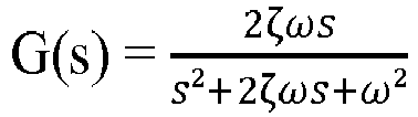
- Equation (1) is a discrete equation of a transfer function G(s) expressed by the following equation (2).
- G s 2 ⁇ s s 2 + 2 ⁇ s + ⁇ 2 wherein ⁇ represents an attenuation coefficient, and ⁇ is a response frequency.
- the response frequency ⁇ is defined by a combustion frequency of the engine 10, and the constants k1 - k4 are determined based on the response frequency ⁇ .
- the combustion frequency is an angle frequency indicative of the number of combustion every unit angle. In a case of a four-cylinder engine, the combustion period (combustion angle period) is 180°CA, and the combustion frequency is an inverse of the combustion period.
- An integrating means M2 shown in FIG. 3 integrates the current torque correspondent Neflt in a constant range every combustion period of each cylinder in order to obtain cylinder workloads Sneflt #1 - Sneflt #4 respectively.
- the NE pulses outputted every 30°CA are numbered with NE pulse numbers 0 - 23.
- the NE pulse numbers 0 - 5 are given to the combustion period of the first cylinder
- the NE pulse numbers 6 - 11 are given to the combustion period of the third cylinder
- the NE pulse numbers 12- 17 are given to the fourth cylinder
- the NE pulse numbers 18 - 23 are given to the second cylinder.
- Sneflt#1 - Sneflt #4 of the first to the fourth cylinder are respectively calculated based on the following equation (3).
- Sneflt# 1 Neflt 0 + Neflt 1 + Neflt 2 + Neflt 3 + Neflt 4 + Neflt 5
- Sneflt# 3 Neflt 6 + Neflt 7 + Neflt 8 + Neflt 9 + Neflt 10 + Neflt 11
- Sneflt# 4 Neflt 12 + Neflt 13 + Neflt 14 + Neflt 15 + Neflt 16 + Neflt 17
- Sneflt# 2 Neflt 18 + Neflt 19 + Neflt 20 + Neflt 21 + Neflt 22 + Neflt 23
- the number of the cylinder will be expressed by #i, and the cylinder workloads Sneflt#1 - Sneflt#4 are expressed by Sneflt#i, hereinafter.
- FIG. 4 is a time chart showing the rotation speed Ne, the current torque correspondent Neflt, and the cylinder workloads Sneflt#i.
- the current torque correspondent Neflt periodically increases and decrease with respect to a reference reveal Ref.
- the cylinder workload Sneflt#i is obtained by integrating the current torque correspondent Neflt in the combustion period of each cylinder.
- the integrated value of the positive current torque correspondent Neflt corresponds to the combustion torque
- the integrated value of the negative current torque correspondent Neflt corresponds to the load torque.
- the reference level Ref is determined based on the average rotation speed between cylinders.
- the cylinder workload Sneflt#i has some variation. For example, in the first cylinder #1, the cylinder workload Sneflt#1 is larger than zero, and in the second cylinder #2, the cylinder workload Sneflt#2 is less than zero.
- the cylinder workload Sneflt#i shows differences of workloads between cylinders with respect to the theoretical value.
- FIG. 5 is a flowchart showing a calculating process of the learning value of each cylinder. This process is conducted by the ECU 20 when the NE pulse rises.
- step S101 a time interval of NE pulse is calculated based on the present NE pulse timing and the previous NE pulse timing in order to calculate a present rotation speed Ne (current rotation speed).
- step S102 the current torque correspondent Neflt(i) is calculated based on the above equation (1).
- step S103 the present NE pulse number is determined.
- steps S104 - S107 the cylinder workload Snflt#i is calculated with respect to each cylinder #1 - #4. That is, when the NE pulse number is 0 - 5, the cylinder workload Sneflt#1 of the first cylinder #1 is calculated in step 104. When the NE pulse number is 6 - 11, the cylinder workload Sneflt#3 of the third cylinder #3 is calculated in step S105. When the NE pulse number is 12 - 17, the cylinder workload Sneflt#4 of the fourth cylinder #4 is calculated in step S106. When the NE pulse number is 18 - 23, the cylinder workload Sneflt#2 of the second cylinder #2 is calculated in step S107.
- step S108 it is determined whether a learning condition of the cylinder workload is established.
- the learning condition is satisfied when the cylinder workloads of all cylinders have been calculated, a power transmission apparatus of a vehicle has been in a predetermined condition (a clutch is completely engaged), and an environmental condition has been predetermined situation (temperature of the engine coolant is higher than a predetermined temperature).
- step S108 When the answer is NO in step S108, the procedure ends.
- step S109 the number of integration times nitgr is incremented by 1, and a workload learning value Qlp#i is calculated based on a following equation (4).
- the cylinder workload Sneflt#i is made zero.
- Qlp#i Qlp#i + Ka ⁇ Sneflt#i
- step S110 it is determined whether the number of integration times nitgr has reached a predetermined number of times kitgr. When the number nitgr is lager than or equal to the number kitgr, the procedure proceeds to step S111.
- step S111 the final learning value of workload Qlrn#i of each cylinder is calculated based on the following equation (5). The workload learning value Qlp#i is made zero, and the number of integration times nitgr is made zero.
- Qlrn#i Qlrn#i + Kb ⁇ Qlp#i / kitgr
- the workload learning value Qlp#i is averaged every integrating times to update the final learning value of workload Qlrn#i. By averaging the workload learning value Qlp#i, the error of the workload learning value Qlp#i can be canceled.
- a differential learning value ⁇ Qlrn#i between cylinders is calculated based on the following equation (6).
- ⁇ Qlrn#i Qlrn#i ⁇ ⁇ Qlrn#i / 4
- a dispersion of the final learning value of workload Qlrn#i is calculated with respect to the average ( ⁇ Qlrn#i / 4) of the final learning value of workload Qlrn#i.
- the final learning value of workload Qlrn#i and the differential learning value ⁇ Qlrn#i are stored in a memory, such as an EEPROM or a stand-by RAM. Multiple driving regions are defined based on the fuel injection amount and the rotation speed as parameters. The values Qlrn#i and ⁇ Qlrn#i are stored every driving regions.
- step S201 parameters indicative of the engine driving condition, such as rotation speed (an average rotation speed) or an accelerator position, are read.
- a basic fuel injection amount is calculated based on the engine driving condition. The basic fuel injection amount may be corrected on the basis of the temperature of the engine coolant and a common rail pressure.
- step S203 the learning value (the final learning value of workload Qlrn#i, or the differential learning value ⁇ Qlrn#i) is read with respect to the subject cylinder.
- step S204 a command fuel injection amount (target fuel injection amount) is calculated by correcting the basic fuel injection amount.
- the fuel injection amount can be corrected by canceling an absolute characteristics error in each cylinder.
- a deviation between the target workload and the final learning value of workload Qlrn#i is calculated.
- the correction amount of the fuel injection amount is calculated based on the deviation to correct the basic fuel injection amount.
- the fuel injection amount can be corrected by canceling the dispersion of characteristics between cylinders.
- the correction amount of fuel injection is calculated based on the differential learning value ⁇ Qlrn#i with respect to every cylinders.
- the basic fuel injection amount is corrected based on the correction amount.
- step S205 a fuel injection period is calculated based on the rotation speed and the command fuel injection amount.
- the fuel is injected into a combustion chamber (not shown) through the injector 11 during the fuel injection period.
- a fuel injection start timing, an ignition timing, a fuel injection terminating timing, and deviations (dispersions) of each timing can be estimated.
- FIG. 7 is a time chart showing the current torque correspondent of a specific cylinder.
- t11, t12, t13, and t14 represent output timings of NE pulse.
- the current torque correspondent Neflt is calculated in these timings.
- the rotation speed increases.
- the time of t11 is the output timing of No. 23 pulse
- the time of t12 is the output timing of No. 0 pulse.
- the rotation speed decreases.
- the time of t13 is the output timing of No. 5 pulse
- the timing of t14 is the output timing of No. 6 pulse.
- a reference time instance Tc0 is predetermined.
- the time instance Tc is compared with the reference time instance Tc0 to calculate the deviation time ⁇ Tc of fuel injection starting timing and the ignition timing.
- ⁇ Tc K 1 ⁇ Tc ⁇ Tc 0
- the calculated fuel injection starting timing or the calculated ignition timing are compared with each other between respective cylinders.
- This difference between respective cylinders can be derived by calculating the average and obtaining a difference between the average and calculated value.
- a reference time instance Tf0 is predetermined.
- the time instance Tf is compared with the reference time instance Tf0 to calculate the deviation time ⁇ Tc of fuel injection stop timing.
- ⁇ Tf K 2 ⁇ Tf ⁇ Tf 0
- the calculated fuel injection stop timings are compared with each other between respective cylinders.
- This difference between respective cylinders can be derived by calculating the average and obtaining a difference between the average and calculated value.
- FIG. 8 is a flowchart showing a fuel injection start timing estimating process.
- step S301 it is determined whether NE pulse number is a predetermined pulse number "n". For example, in the first cylinder #1, "n" is 23.
- the present time instance is stored as Ta in step S302.
- step S303 the present current torque correspondent Neflt is stored as Ya.
- step S304 it is determined whether the NE pulse number is "n+1". For example, in the first cylinder #1, "n" is 0. When the NE pulse number is "n+1", the present time instance is stored as Tb in step S305. In step S306, the present current torque correspondent Neflt is stored as Yb.
- step S307 the time instance Tc in which the current torque correspondent Neflt is the threshold Yc is calculated to estimate the fuel injection starting timing.
- step S308 a deviation of the fuel injection starting timing is estimated based on the above equation (8).
- the command fuel injection period is corrected based on the estimated value.
- the ignition timing and the fuel injection stop timing are calculated according to the process shown in FIG. 8 by use of the equations (7) - (10).
- the current torque correspondent Neflt can be obtained appropriately based on the fuel injection condition and the combustion condition. Furthermore, the current torque correspondent Neflt is integrated within the specific range with respect to each cylinder so that the cylinder workload Sneflt#i is calculated.
- the fuel injection amount is adjusted cylinder-by-cylinder based on the cylinder workload Sneflt#i of each cylinder (actually, the final learning value of workload Qlrn#i, or the differential learning value ⁇ Qlrn#i), so that the characteristics of each cylinder can be desirably controlled. Hence, the emission is restricted and the drivability is enhanced.
- the absolute dispersion of characteristics of each cylinder can be detected as well as the relative dispersion between cylinders, so that various controls can be performed cylinder by cylinder.
- the band-pass filter (BPF) is utilized as a filtering means, the varying components of low frequency due to acceleration or deceleration and the varying components of high frequency of noise can be eliminated from the rotation speed signal in order to extract only torque varying components. Thereby, the current torque correspondent Neflt can be accurately calculated to reduce the dispersion of characteristics between cylinders.
- the fuel injection timing, the ignition timing, and the fuel injection stop timing can be estimated based on the current torque correspondent Neflt, the dispersion of fuel injection timing, the ignition timing, and the fuel injection stop timing can be restricted.
- the command fuel injection amount is calculated by correcting the fuel injection amount based on the learning values.
- the command furl injection period can be corrected based on the learning values.
- the cylinder workload Sneflt#i is calculated by integrating the current torque correspondent Neflt in a combustion period.
- the workload due to the combustion and the workload due to the load can be respectively calculated.
- the current torque correspondent Neflt is integrated in a specific range in which the rotation speed increases in order to obtain the workload due to the combustion.
- the current torque correspondent Neflt is integrated in a specific range in which the rotation speed decreases in order to obtain the workload due to the load.
- the fuel injection amount is controlled based on each workload.
- the current torque correspondent Neflt varies according to the stroke of the piston and a rotational angle position of the crankshaft. This variation depends on the combustion torque, an inertia torque, and the load torque.
- FIG. 10A -10E respectively show the rotation speed, the combustion torque, the inertia torque, the load torque, and the current torque correspondent.
- an area denoted by "D1" corresponds to the workload due to the combustion
- an area denoted by "D2" corresponds to the workload due to the load.
- the cylinder workload Sneflt#i is calculated at the time when combustion is occurred and at the time when the combustion is not occurred. A difference between these cylinder workloads is calculated to obtain the workload due to combustion. When the combustion is not occurred, the fuel injection is not conducted, so that the cylinder workload Sneflt#i does not includes the workload corresponding to the combustion torque.
- the current torque correspondent Neflt is a sum of the combustion torque, the inertia torque, and the load torque.
- the current torque correspondent Neflt is a sum of the inertia torque and the load torque. That is, the current torque correspondent is different between the combustion period and the non-combustion period.
- step S401 it is determined whether it is a fuel-cut period.
- the procedure proceeds to step S402 in which the cylinder workload Sneflt#i at the time of combustion is calculated.
- the procedure proceeds to step S403 in which the cylinder workload Sneflt#i at the time of non-combustion is calculated.
- step 404 it is determined whether the cylinder workload Sneflt#i has been calculated at both situations.
- step S405 the procedure proceeds to step S405 in which the cylinder workload Sneflt#i is calculated by subtracting the cylinder workload at the fuel-cut period from the cylinder workload at the combustion period.
- the combustion torque of each cylinder can be calculated based on a difference between the current torque correspondent Neflt which is obtained during combustion period and the current torque correspondent Neflt which is obtained during non-combustion period.
- the differential combustion torque between cylinders can be calculated by comparing the combustion torque of each cylinder.
- the rotation speed Ne starts to increase at the time of "A1", “A2", and “A3" in a cylinder.
- An angle between “A1” and “A2” and an angle between "A2” and “A3” correspond to combustion angle periods.
- the combustion torque starts to increase at a time of stating of combustion, and starts to decrease at a time of terminating of combustion.
- the inertia torque varies according to a rotational inertia torque of a flywheel (not shown).
- FIG. 10C when the rotation speed increases, the inertia torque generally becomes negative values, and when the rotation speed decreases, the inertial torque generally becomes positive values.
- the load torque is always negative value and varies in a small range. The sum of the combustion torque, the inertia torque, and the load torque corresponds to the current torque correspondent.
- each cylinder has different current torque correspondent Neflt.
- the current torque correspondent Neflt (C1, C2) corresponds to the characteristics of each cylinder. Peak values and bottom values of the current torque correspondent Neflt are different between cylinders.
- the current torque correspondent Neflt is calculated at the same rotational angle position with respect to each cylinder, and then the characteristics of each cylinder can be estimated based on the current torque correspondent. Alternatively, the difference in characteristics between the cylinders can be estimated by comparing the current torque correspondent Neflt between the cylinders. In a structure that the NE pulse has the pulse number, the current torque correspondent Neflt can be calculated with respect to the NE pulse having the same pulse number. Multiple rotational angle positions are provided to calculate the current torque correspondent Neflt. These multiple angle positions are substantially equal to each other.
- the peak value or the bottom value of the current torque correspondent Neflt is obtained to estimate the characteristics of each cylinder.
- the difference in characteristics between cylinders can be estimated by comparing at least one of the peak value and the bottom value between cylinders.
- the characteristics of each cylinder can be evaluated based on the peak value of the current torque correspondent, the bottom value of the current torque correspondent, or the difference between the peak value and the bottom value.
- a low-pass filter (LPF) or a high-pass-filter (HPF) can be used instead of the band-pass filter (BPF).
- the combustion frequency is a response frequency ⁇ of the transfer function which defines the LPH or the HPF, whereby the current torque correspondent can be calculated.
- a resolver can be used to detect the rotational position of the crankshaft linearly.
- the current torque correspondent Neflt can be calculated at arbitrary timing.
- the current torque correspondent Neflt is continuously calculated to estimate the fuel injection start timing, the ignition timing, or fuel injection stop timing.
- the time instance is measured.
- the fuel injection start timing, the ignition timing, or the fuel injection stop timing can be directly estimated from the measured time instance.
- FIG. 11 is a flowchart showing a process for correcting a dispersion in fuel injection amount between cylinders.
- a current rotation speed shown in FIG. 13 is measured. Specifically, the current rotation speed is derived from a pulse interval between a first rotational angle (ATDC 42°) and a second rotational angel (ATDC 72°).
- ADC 42° first rotational angle
- ATDC 72° second rotational angel
- step S20 it is determined whether the present measured data (the current rotation speed) and the previous measured data are in the same region with respect to multiple regions which are defined in data map "A" having coordinate axes of the rotation speed and the fuel injection amount.
- step S30 the procedure proceeds to step S30.
- step S10 the procedure goes back to step S10.
- a data map "B” having coordinate axes of the common rail pressure and the fuel injection amount.
- the data map "B” is shown in FIG. 16 .
- step S10 The measured data in step S10 is inputted into a low-pass filter M10 shown in FIG. 12 to extract low-frequency components.
- step S40 the extracted data is stored in the corresponding region defined by the data map "A" or data map "B". The stored data of each cylinder is integrated respectively. In this embodiment, since the diesel engine has four cylinders, four integrated data are generated by low-pass filter M10.
- step S50 it is determined whether the number of data stored in the specific region has reached a predetermined number.
- the procedure proceeds to step S60.
- the answer is No, the procedure goes back to step S10.
- step S60 the data is averaged by an averaging means M20 shown in FIG. 12 , whereby the dispersion in fuel injection amount cylinders is extracted as shown in FIG. 14.
- FIG. 14 shows dispersion in fuel injection amount due to the individual difference between injectors. The magnitude of the dispersion dQ in the fuel injection amount is expressed by a numeral "0" to "5".
- the dispersion of the speed between cylinders #1 to #4 is illustrated in FIG. 14 . With respect to cylinders #1, and #4, the dispersion dQ in fuel injection amount is the positive value. With respect to cylinders #3, and #2, the dispersion dQ is the negative value.
- FIG. 14 shows the averaged value of the filter output with respect to the crank angel.
- the filter output is added by the amount of 2 mm 3 /stroke relative to the averaged amount with respect to the cylinders #1, and #4 in order to average the filtered output.
- the filter output is subtracted by the amount of 2 mm 3 /stroke relative to the averaged amount with respect to the cylinders #3, and #2 in order to average the filtered output.
- the data is obtained between the first rotational angel (ATDC 42°) and the second rotational angel (ATDC 72°).
- the averaged process value of the filter output between the first rotational angel and the second rotational angel shown in FIG. 14 is obtained in step S60.
- step S60 The averaging process in step S60 is described in detail hereinafter.
- the integrated data obtained in step S40 is divided by the predetermined value to calculate the average of the integrated data with respect to each cylinder.
- Four averages are obtained. These four averages are integrated and divided by the number of cylinder (four, in this example) to calculate the whole average.
- the deviation of each cylinder is calculated by subtracting the individual average of each cylinder from the whole average of every cylinder. This deviation is converted into a value to the fuel injection amount to calculate the fuel injection correction amount "q".
- step S70 the fuel injection amount is corrected in such a manner as to reduce the dispersion in fuel injection amount between the cylinders.
- the corrected command fuel injection amount Qf is calculated by adding the correction amount "q" on the command fuel injection amount Q.
- the fuel injector 11 is controlled based on the corrected command fuel injection amount Qf.
- the current rotation speed of each cylinder is filtered by low-pass filter M10 to obtain the low-frequency components, so that the high-frequency noise is eliminated to accurately detect the rotational variation between cylinders.
- the predetermined piece of data is integrated and is averaged, so that only the dispersion of the fuel injection between the cylinders can be detected.
- the fuel injection amount is corrected in such a manner as to reduce the dispersion between cylinders, so that the dispersion in the rotation speed between cylinders can be restricted.
- the above-described control can be applied to whole driving rage of engine.
- the dispersion of the rotation speed between cylinders can be corrected even when the engine is running in a normal speed as well as idling speed in order to reduce the emission and enhance the drivability.
- the data filtered by the low-pass filter M10 is stored in the data map "A" or the data map "B", and the predetermined piece of data is integrated and averaged in every region. Thereby, the fuel injection correction amount can be derived every regions whish are defined in the data map "A” or "B".
- the fuel injection correction amount learned in the low-load and low-speed region is not used in the high-load and high-speed region, so that the appropriate correction can be performed in a whole driving range of the engine.
- the present embodiment can be applied to a gasoline engine as well as the diesel engine.
- a sensor signal from a speed sensor (18) is inputted into an ECU (20).
- the ECU (20) calculates a rotation speed of a crankshaft (17) in a predetermined period based on the sensor signal.
- the rotation speed is filtered by a frequency which is defined based on a combustion frequency of the engine (10) to obtain a value corresponding to a current torque.
- the ECU (20) calculates a workload of each cylinder based on the value corresponding to the current torque, and controls characteristic of each cylinder based on the workload.
Landscapes
- Engineering & Computer Science (AREA)
- Chemical & Material Sciences (AREA)
- Combustion & Propulsion (AREA)
- Mechanical Engineering (AREA)
- General Engineering & Computer Science (AREA)
- Combined Controls Of Internal Combustion Engines (AREA)
- Electrical Control Of Air Or Fuel Supplied To Internal-Combustion Engine (AREA)
Claims (17)
- Appareil de commande d'injection de carburant pour un moteur à combustion interne multicylindre comprenant :un moyen de calcul (20) pour le calcul d'une vitesse de rotation d'un vilebrequin (17) du moteur à combustion interne (10) ;un moyen de filtration (20, M1) composé d'un filtre passe-bande qui filtre la vitesse de rotation par une bande de fréquence qui est définie sur la base d'une fréquence de combustion, qui est l'inverse d'une période de combustion, du moteur à combustion interne (10) afin d'obtenir une valeur (Neflt) correspondant à un couple courant de sorte à éliminer des composants haute fréquence de bruit et des composants basse fréquence dus à l'accélération ou à la décélération ; etun moyen de contrôle (20, 11) pour contrôler une caractéristique de chaque cylindre du moteur à combustion interne (10) sur la base de la valeur correspondant au couple courant,dans lequel la valeur (Neflt) est obtenue par l'équation suivante (1) :

 dans lequel ζ représente un coefficient d'atténuation et ω est une fréquence de réponse ; etdans lequel la correspondance de couple courant Neflt (i) est calculée chaque fois que la vitesse de rotation (Ne) est entrée dans le filtre (M1).
 - Appareil de commande d'injection de carburant selon la revendication 1, dans lequel le moyen de filtration (20, M1) est défini par une fonction de transfert, dont la fréquence de réponse est la fréquence de combustion.
- Appareil de commande d'injection de carburant selon la revendication 1 ou 2, dans lequel
la valeur (Neflt) correspondant au couple courant est obtenue à chaque angle de rotation prédéterminé par rapport à chaque cylindre, et la caractéristique de chaque cylindre est estimée sur la base de la valeur (Neflt) correspondant au couple courant. - Appareil de commande d'injection de carburant selon la revendication 1 ou 2, dans lequel
la valeur (Neflt) correspondant au couple courant est obtenue à chaque angle de rotation prédéterminé par rapport à chaque cylindre, et une différence de caractéristique de chaque cylindre est estimée en comparant la valeur (Neflt) correspondant au couple courant entre des cylindres. - Appareil de commande d'injection de carburant selon la revendication 1 ou 2, dans lequel
au moins une d'une valeur maximale et une valeur minimale de la valeur (Neflt) correspondant au couple courant de chaque cylindre est obtenue, et la caractéristique de chaque cylindre est estimée sur la base de la valeur obtenue. - Appareil de commande d'injection de carburant selon la revendication 1 ou 2, dans lequel
au moins une d'une valeur maximale et une valeur minimale de la valeur (Neflt) correspondant au couple courant de chaque cylindre est obtenue, et une différence de caractéristique entre les cylindres est estimée en comparant la valeur obtenue entre les cylindres. - Appareil de commande d'injection de carburant selon la revendication 1 ou 2, dans lequel
un couple de combustion est calculé sur la base d'une différence entre la valeur (Neflt) correspondant au couple courant qui est calculée sur une condition de combustion et la valeur (Neflt) correspondant au couple courant qui est calculée sur une condition de non combustion. - Appareil de commande d'injection de carburant selon l'une quelconque des revendications 1 à 7, comprenant en outre :un moyen (20) pour calculer au moins une d'une charge de travail respective (Sneflt) et une charge de travail totale (Sneflt) d'une combustion, une force d'inertie, et une charge par intégration de la valeur correspondant au couple courant de chaque cylindre dans une étendue prédéterminée.
- Appareil de commande d'injection de carburant selon l'une quelconque des revendications 1 à 7, comprenant en outre :un moyen (20) pour calculer au moins une des différences d'une charge de travail respective (Sneflt) et une charge de travail totale (Sneflt) d'une combustion, une force d'inertie, et une charge entre des cylindres par intégration de la valeur (Neflt) correspondant au couple courant de chaque cylindre dans une étendue prédéterminée et en comparant des valeurs intégrées entre les cylindres.
- Appareil de commande d'injection de carburant selon l'une quelconque des revendications 1 à 7, comprenant en outre :un moyen (20) pour calculer au moins une d'une charge de travail respective (Sneflt) et une charge de travail totale (Sneflt) d'une combustion, une force d'inertie, et une charge, comme un paramètre de condition de combustion, par intégration de la valeur (Neflt) correspondant au couple courant de chaque cylindre dans une étendue prédéterminée ;un moyen (20) pour calculer une moyenne des paramètres de condition de combustion de chaque cylindre ; etun moyen (20) pour calculer une différence entre la moyenne des paramètres de condition de combustion et le paramètre de condition de combustion de chaque cylindre.
- Appareil de commande d'injection de carburant selon l'une quelconque des revendications 8 à 10, dans lequel
la charge de travail (Sneflt) de chaque cylindre est calculée par intégration de la valeur (Neflt) correspondant au couple courant dans une étendue prédéterminée pendant une période de combustion et une période de non combustion, et la charge de travail (Sneflt) de la combustion de chaque cylindre est calculée sur la base d'une différence entre la charge de travail pendant la période de combustion et la charge de travail pendant la période de non combustion. - Appareil de commande d'injection de carburant selon l'une quelconque des revendications 8 à 10, dans lequel
la charge de travail respective (Sneflt), la charge de travail totale (Sneflt) ou une différence de celles-ci entre des cylindres est enregistrée comme une valeur d'apprentissage. - Appareil de commande d'injection de carburant selon l'une quelconque des revendications 1 à 12, comprenant en outre :un moyen (20) pour estimer un timing de démarrage d'injection de carburant ou un timing d'allumage par comparaison de la valeur (Neflt) correspondant au couple courant avec un seuil prédéterminé dans une situation, dans laquelle la valeur (Neflt) correspondant au couple courant de chaque cylindre augmente.
- Appareil de commande d'injection de carburant selon l'une quelconque des revendications 1 à 13, comprenant en outre :un moyen (20) pour estimer un timing d'arrêt d'injection de carburant par comparaison de la valeur (Neflt) correspondant au couple courant avec un seuil prédéterminé dans une situation, dans laquelle la valeur (Neflt) correspondant au couple courant de chaque cylindre diminue.
- Appareil de commande d'injection de carburant selon l'une quelconque des revendications 1 à 14, comprenant en outre :un moyen (20) pour estimer un timing de démarrage d'injection de carburant ou un timing d'allumage par comparaison de la valeur (Neflt) correspondant au couple courant avec un seuil prédéterminé dans une situation, dans laquelle la valeur (Neflt) correspondant au couple courant de chaque cylindre augmente, et pour calculer une différence de timing de démarrage d'injection de carburant ou timing d'allumage entre chaque cylindre.
- Appareil de commande d'injection de carburant selon l'une quelconque des revendications 1 à 15, comprenant en outre :un moyen (20) pour estimer un timing d'arrêt d'injection de carburant par comparaison de la valeur (Neflt) correspondant au couple courant avec un seuil prédéterminé, et pour calculer une différence de timing d'arrêt d'injection de carburant entre les cylindres dans une situation, dans laquelle la valeur (Neflt) correspondant au couple courant de chaque cylindre diminue.
- Procédé de commande d'injection de carburant pour un moteur à combustion interne multicylindre comprenant :le calcul d'une vitesse de rotation d'un vilebrequin (17) du moteur à combustion interne (10) ;la filtration par passe-bande de la vitesse de rotation par une bande de fréquence qui est définie sur la base d'une fréquence de combustion, qui est l'inverse d'une période de combustion, du moteur à combustion interne (10) afin d'obtenir une valeur (Neflt) correspondant à un couple courant de sorte à éliminer des composants haute fréquence de bruits et des composants basse fréquence dus à l'accélération ou à la décélération ; etle contrôle d'une caractéristique de chaque cylindre du moteur à combustion interne (10) sur la base de la valeur (Neflt) correspondant au couple courant,dans lequel la valeur (Neflt) est obtenue par l'équation suivante :

 dans lequel ζ représente un coefficient d'atténuation et ω est une fréquence de réponse ; etdans lequel la correspondance de couple courant Neflt (i) est calculée chaque fois que la vitesse de rotation (Ne) est entrée dans le filtre (M1).
Applications Claiming Priority (3)
| Application Number | Priority Date | Filing Date | Title |
|---|---|---|---|
| JP2005182117 | 2005-06-22 | ||
| JP2005221476A JP4400526B2 (ja) | 2005-07-29 | 2005-07-29 | 内燃機関用制御装置 |
| JP2006133801A JP2007032557A (ja) | 2005-06-22 | 2006-05-12 | 燃料噴射制御装置 |
Publications (3)
| Publication Number | Publication Date |
|---|---|
| EP1736659A2 EP1736659A2 (fr) | 2006-12-27 |
| EP1736659A3 EP1736659A3 (fr) | 2011-11-30 |
| EP1736659B1 true EP1736659B1 (fr) | 2017-01-11 |
Family
ID=36763779
Family Applications (1)
| Application Number | Title | Priority Date | Filing Date |
|---|---|---|---|
| EP06115820.0A Not-in-force EP1736659B1 (fr) | 2005-06-22 | 2006-06-21 | Dispositif de commande de l'injection de carburant pour un moteur à combustion interne |
Country Status (4)
| Country | Link |
|---|---|
| US (1) | US7317983B2 (fr) |
| EP (1) | EP1736659B1 (fr) |
| KR (1) | KR100791163B1 (fr) |
| ES (1) | ES2621134T3 (fr) |
Families Citing this family (21)
| Publication number | Priority date | Publication date | Assignee | Title |
|---|---|---|---|---|
| JP4621627B2 (ja) * | 2006-04-24 | 2011-01-26 | 本田技研工業株式会社 | 内燃機関の仕事量算出装置 |
| JP4552899B2 (ja) * | 2006-06-06 | 2010-09-29 | 株式会社デンソー | 燃料噴射制御装置 |
| JP4353220B2 (ja) * | 2006-08-29 | 2009-10-28 | 株式会社デンソー | 内燃機関の燃料噴射制御装置 |
| JP4281784B2 (ja) * | 2006-11-10 | 2009-06-17 | トヨタ自動車株式会社 | 内燃機関装置およびこれを備える動力出力装置並びにこれを搭載する車両、内燃機関装置の制御方法 |
| US7480557B2 (en) * | 2006-11-17 | 2009-01-20 | Honda Motor Co., Ltd. | Control system for internal combustion engine |
| JP4503631B2 (ja) * | 2007-05-18 | 2010-07-14 | 本田技研工業株式会社 | 内燃機関の制御装置 |
| JP4424380B2 (ja) * | 2007-06-20 | 2010-03-03 | 株式会社デンソー | 噴射量制御装置およびそれを用いた燃料噴射システム |
| JP4861921B2 (ja) * | 2007-07-26 | 2012-01-25 | ヤンマー株式会社 | 燃料噴射量補正機能付エンジン |
| DE102007037037B3 (de) * | 2007-08-06 | 2009-02-12 | Mtu Friedrichshafen Gmbh | Verfahren zur Regelung einer Brennkraftmaschine |
| JP4442670B2 (ja) * | 2007-09-19 | 2010-03-31 | 株式会社デンソー | 内燃機関の燃料噴射制御装置 |
| JP4577348B2 (ja) * | 2007-10-24 | 2010-11-10 | 株式会社デンソー | 内燃機関制御装置及び内燃機関制御システム |
| JP5297459B2 (ja) * | 2008-07-31 | 2013-09-25 | 株式会社フチノ | 原動機のトルク計測装置及びその方法、並びに制御プログラム |
| JP2010275989A (ja) * | 2009-06-01 | 2010-12-09 | Denso Corp | 内燃機関の燃料噴射制御装置 |
| JP5103459B2 (ja) * | 2009-10-30 | 2012-12-19 | 日立オートモティブシステムズ株式会社 | エンジンの制御装置 |
| JP5168336B2 (ja) | 2010-10-05 | 2013-03-21 | 株式会社デンソー | 内燃機関の制御装置 |
| US8051704B2 (en) * | 2010-11-19 | 2011-11-08 | Ford Global Technologies, Llc | Method for diagnosing fuel injectors |
| DE102011103988A1 (de) * | 2011-06-10 | 2012-12-13 | Mtu Friedrichshafen Gmbh | Verfahren zur Raildruckregelung |
| JP5459302B2 (ja) | 2011-12-26 | 2014-04-02 | 株式会社デンソー | 内燃機関制御システムの異常診断装置 |
| DE102019219541B4 (de) * | 2019-12-13 | 2021-08-05 | Vitesco Technologies GmbH | Verfahren und Motorsteuerung zur Mehrfacheinspritzung mit Mengenkorrektur für einen Verbrennungsmotor |
| CN116867961B (zh) * | 2021-03-10 | 2026-03-27 | 日立安斯泰莫株式会社 | 电子控制装置及燃烧状态检测系统 |
| JP7101841B1 (ja) * | 2021-04-16 | 2022-07-15 | 三菱電機株式会社 | 内燃機関の制御装置及び制御方法 |
Family Cites Families (11)
| Publication number | Priority date | Publication date | Assignee | Title |
|---|---|---|---|---|
| US4532592A (en) * | 1982-12-22 | 1985-07-30 | Purdue Research Foundation | Engine-performance monitor and control system |
| US4715339A (en) * | 1984-09-01 | 1987-12-29 | Kawasaki Jukogyo Kabushiki Kaisha | Governor for internal combustion engine |
| US4697561A (en) * | 1985-04-15 | 1987-10-06 | Purdue Research Foundation | On-line engine torque and torque fluctuation measurement for engine control utilizing crankshaft speed fluctuations |
| JPS62197657A (ja) | 1986-02-26 | 1987-09-01 | Hitachi Ltd | 内燃機関の制御装置 |
| JP2793729B2 (ja) * | 1991-10-09 | 1998-09-03 | 株式会社日立製作所 | エンジンの燃料噴射量制御装置 |
| JPH0778359B2 (ja) | 1992-07-24 | 1995-08-23 | 前田製管株式会社 | アースオーガ機の排土装置 |
| JP3393626B2 (ja) * | 1994-09-19 | 2003-04-07 | 株式会社日立ユニシアオートモティブ | 内燃機関の点火時期制御装置 |
| DE19527218B4 (de) | 1994-12-23 | 2004-03-18 | Robert Bosch Gmbh | Verfahren und Vorrichtung zur Regelung der Laufruhe einer Brennkraftmaschine |
| IT1279073B1 (it) | 1994-12-23 | 1997-12-04 | Bosch Gmbh Robert | Procedimento e dispositivo per la regolazione della silezionsita' di funzionamento di un motore endotermico |
| DE19633066C2 (de) * | 1996-08-16 | 1998-09-03 | Telefunken Microelectron | Verfahren zur zylinderselektiven Steuerung einer selbstzündenden Brennkraftmaschine |
| EP1260693B1 (fr) * | 2001-05-25 | 2008-05-28 | Mazda Motor Corporation | Système de commande pour moteur à combustion interne |
-
2006
- 2006-06-20 US US11/455,702 patent/US7317983B2/en active Active
- 2006-06-21 ES ES06115820.0T patent/ES2621134T3/es active Active
- 2006-06-21 KR KR1020060055897A patent/KR100791163B1/ko not_active Expired - Fee Related
- 2006-06-21 EP EP06115820.0A patent/EP1736659B1/fr not_active Not-in-force
Non-Patent Citations (1)
| Title |
|---|
| None * |
Also Published As
| Publication number | Publication date |
|---|---|
| KR20060134828A (ko) | 2006-12-28 |
| ES2621134T3 (es) | 2017-07-03 |
| KR100791163B1 (ko) | 2008-01-02 |
| EP1736659A2 (fr) | 2006-12-27 |
| EP1736659A3 (fr) | 2011-11-30 |
| US20060293828A1 (en) | 2006-12-28 |
| US7317983B2 (en) | 2008-01-08 |
Similar Documents
| Publication | Publication Date | Title |
|---|---|---|
| EP1736659B1 (fr) | Dispositif de commande de l'injection de carburant pour un moteur à combustion interne | |
| EP2039917B1 (fr) | Système d'injection de carburant doté d'une fonction d'apprentissage de la quantité d'injection | |
| EP0924421B1 (fr) | Dispositif pour régler l'injection de carburant pour moteur à combustion interne | |
| US8977471B2 (en) | Controller for internal combustion engine | |
| EP0921296A2 (fr) | Dispositif de commande d'injection de carburant pour moteur à combustion interne | |
| US7343240B2 (en) | Fuel injection controller | |
| US7725242B2 (en) | Controller of internal combustion engine | |
| JP5482532B2 (ja) | 燃料噴射制御装置 | |
| CN100432406C (zh) | 内燃机的燃料喷射控制设备 | |
| US8620563B2 (en) | Fuel supply apparatus for internal combustion engine | |
| JP4400526B2 (ja) | 内燃機関用制御装置 | |
| JP2008184915A (ja) | 内燃機関の燃料噴射制御装置 | |
| JP4424380B2 (ja) | 噴射量制御装置およびそれを用いた燃料噴射システム | |
| JP3876766B2 (ja) | 内燃機関用噴射率制御装置 | |
| EP2037104B1 (fr) | Procédé de reconnaissance de la volatilité d'un carburant pendant l'étape de post-démarrage d'un moteur à combustion interne | |
| US8483936B2 (en) | Method, recording support and device to calibrate fuel injection | |
| JP2012159009A (ja) | 燃料噴射制御装置 | |
| JP2002089344A (ja) | 燃料噴射装置の経時変化判定装置 | |
| JP4610407B2 (ja) | 内燃機関の燃料噴射装置 | |
| EP2199578B1 (fr) | Dispositif de contrôle de couple et procédé pour moteur à combustion interne | |
| JP2007032557A (ja) | 燃料噴射制御装置 |
Legal Events
| Date | Code | Title | Description |
|---|---|---|---|
| PUAI | Public reference made under article 153(3) epc to a published international application that has entered the european phase |
Free format text: ORIGINAL CODE: 0009012 |
|
| AK | Designated contracting states |
Kind code of ref document: A2 Designated state(s): AT BE BG CH CY CZ DE DK EE ES FI FR GB GR HU IE IS IT LI LT LU LV MC NL PL PT RO SE SI SK TR |
|
| AX | Request for extension of the european patent |
Extension state: AL BA HR MK YU |
|
| PUAL | Search report despatched |
Free format text: ORIGINAL CODE: 0009013 |
|
| AK | Designated contracting states |
Kind code of ref document: A3 Designated state(s): AT BE BG CH CY CZ DE DK EE ES FI FR GB GR HU IE IS IT LI LT LU LV MC NL PL PT RO SE SI SK TR |
|
| AX | Request for extension of the european patent |
Extension state: AL BA HR MK RS |
|
| RIC1 | Information provided on ipc code assigned before grant |
Ipc: F02D 41/40 20060101AFI20111026BHEP Ipc: F02D 41/14 20060101ALI20111026BHEP |
|
| 17P | Request for examination filed |
Effective date: 20120419 |
|
| 17Q | First examination report despatched |
Effective date: 20120530 |
|
| AKX | Designation fees paid |
Designated state(s): DE ES FR GB IT |
|
| GRAP | Despatch of communication of intention to grant a patent |
Free format text: ORIGINAL CODE: EPIDOSNIGR1 |
|
| INTG | Intention to grant announced |
Effective date: 20160822 |
|
| GRAS | Grant fee paid |
Free format text: ORIGINAL CODE: EPIDOSNIGR3 |
|
| GRAA | (expected) grant |
Free format text: ORIGINAL CODE: 0009210 |
|
| AK | Designated contracting states |
Kind code of ref document: B1 Designated state(s): DE ES FR GB IT |
|
| REG | Reference to a national code |
Ref country code: GB Ref legal event code: FG4D |
|
| REG | Reference to a national code |
Ref country code: DE Ref legal event code: R096 Ref document number: 602006051490 Country of ref document: DE |
|
| REG | Reference to a national code |
Ref country code: FR Ref legal event code: PLFP Year of fee payment: 12 |
|
| REG | Reference to a national code |
Ref country code: ES Ref legal event code: FG2A Ref document number: 2621134 Country of ref document: ES Kind code of ref document: T3 Effective date: 20170703 |
|
| REG | Reference to a national code |
Ref country code: ES Ref legal event code: GC2A Effective date: 20170725 |
|
| REG | Reference to a national code |
Ref country code: DE Ref legal event code: R084 Ref document number: 602006051490 Country of ref document: DE |
|
| REG | Reference to a national code |
Ref country code: GB Ref legal event code: 746 Effective date: 20170809 |
|
| REG | Reference to a national code |
Ref country code: DE Ref legal event code: R097 Ref document number: 602006051490 Country of ref document: DE |
|
| PLBE | No opposition filed within time limit |
Free format text: ORIGINAL CODE: 0009261 |
|
| STAA | Information on the status of an ep patent application or granted ep patent |
Free format text: STATUS: NO OPPOSITION FILED WITHIN TIME LIMIT |
|
| 26N | No opposition filed |
Effective date: 20171012 |
|
| REG | Reference to a national code |
Ref country code: FR Ref legal event code: PLFP Year of fee payment: 13 |
|
| PGFP | Annual fee paid to national office [announced via postgrant information from national office to epo] |
Ref country code: IT Payment date: 20190624 Year of fee payment: 14 |
|
| PGFP | Annual fee paid to national office [announced via postgrant information from national office to epo] |
Ref country code: ES Payment date: 20190722 Year of fee payment: 14 Ref country code: GB Payment date: 20190619 Year of fee payment: 14 |
|
| PGFP | Annual fee paid to national office [announced via postgrant information from national office to epo] |
Ref country code: FR Payment date: 20200619 Year of fee payment: 15 |
|
| GBPC | Gb: european patent ceased through non-payment of renewal fee |
Effective date: 20200621 |
|
| PG25 | Lapsed in a contracting state [announced via postgrant information from national office to epo] |
Ref country code: GB Free format text: LAPSE BECAUSE OF NON-PAYMENT OF DUE FEES Effective date: 20200621 |
|
| PG25 | Lapsed in a contracting state [announced via postgrant information from national office to epo] |
Ref country code: IT Free format text: LAPSE BECAUSE OF NON-PAYMENT OF DUE FEES Effective date: 20200621 |
|
| REG | Reference to a national code |
Ref country code: ES Ref legal event code: FD2A Effective date: 20211105 |
|
| PG25 | Lapsed in a contracting state [announced via postgrant information from national office to epo] |
Ref country code: ES Free format text: LAPSE BECAUSE OF NON-PAYMENT OF DUE FEES Effective date: 20200622 |
|
| PG25 | Lapsed in a contracting state [announced via postgrant information from national office to epo] |
Ref country code: FR Free format text: LAPSE BECAUSE OF NON-PAYMENT OF DUE FEES Effective date: 20210630 |
|
| PGFP | Annual fee paid to national office [announced via postgrant information from national office to epo] |
Ref country code: DE Payment date: 20220620 Year of fee payment: 17 |
|
| REG | Reference to a national code |
Ref country code: DE Ref legal event code: R119 Ref document number: 602006051490 Country of ref document: DE |
|
| PG25 | Lapsed in a contracting state [announced via postgrant information from national office to epo] |
Ref country code: DE Free format text: LAPSE BECAUSE OF NON-PAYMENT OF DUE FEES Effective date: 20240103 |