EP1739275A2 - Volet roulant avec dispositif anti-pincement éléctronique - Google Patents
Volet roulant avec dispositif anti-pincement éléctronique Download PDFInfo
- Publication number
- EP1739275A2 EP1739275A2 EP06001574A EP06001574A EP1739275A2 EP 1739275 A2 EP1739275 A2 EP 1739275A2 EP 06001574 A EP06001574 A EP 06001574A EP 06001574 A EP06001574 A EP 06001574A EP 1739275 A2 EP1739275 A2 EP 1739275A2
- Authority
- EP
- European Patent Office
- Prior art keywords
- roller blind
- motor
- window
- blind according
- window roller
- Prior art date
- Legal status (The legal status is an assumption and is not a legal conclusion. Google has not performed a legal analysis and makes no representation as to the accuracy of the status listed.)
- Withdrawn
Links
Images


Classifications
-
- B—PERFORMING OPERATIONS; TRANSPORTING
- B60—VEHICLES IN GENERAL
- B60J—WINDOWS, WINDSCREENS, NON-FIXED ROOFS, DOORS, OR SIMILAR DEVICES FOR VEHICLES; REMOVABLE EXTERNAL PROTECTIVE COVERINGS SPECIALLY ADAPTED FOR VEHICLES
- B60J1/00—Windows; Windscreens; Accessories therefor
- B60J1/20—Accessories, e.g. wind deflectors, blinds
- B60J1/2011—Blinds; curtains or screens reducing heat or light intensity
- B60J1/2013—Roller blinds
- B60J1/2016—Control means for actuating the roller blind, e.g. using electronic control
-
- B—PERFORMING OPERATIONS; TRANSPORTING
- B60—VEHICLES IN GENERAL
- B60J—WINDOWS, WINDSCREENS, NON-FIXED ROOFS, DOORS, OR SIMILAR DEVICES FOR VEHICLES; REMOVABLE EXTERNAL PROTECTIVE COVERINGS SPECIALLY ADAPTED FOR VEHICLES
- B60J1/00—Windows; Windscreens; Accessories therefor
- B60J1/20—Accessories, e.g. wind deflectors, blinds
- B60J1/2011—Blinds; curtains or screens reducing heat or light intensity
- B60J1/2013—Roller blinds
- B60J1/2019—Roller blinds powered, e.g. by electric, hydraulic or pneumatic actuators
- B60J1/2027—Roller blinds powered, e.g. by electric, hydraulic or pneumatic actuators with a buckle-proof guided flexible actuating element acting on the draw bar for pushing or push-pulling, e.g. a Bowden cable
-
- B—PERFORMING OPERATIONS; TRANSPORTING
- B60—VEHICLES IN GENERAL
- B60J—WINDOWS, WINDSCREENS, NON-FIXED ROOFS, DOORS, OR SIMILAR DEVICES FOR VEHICLES; REMOVABLE EXTERNAL PROTECTIVE COVERINGS SPECIALLY ADAPTED FOR VEHICLES
- B60J1/00—Windows; Windscreens; Accessories therefor
- B60J1/20—Accessories, e.g. wind deflectors, blinds
- B60J1/2011—Blinds; curtains or screens reducing heat or light intensity
- B60J1/2013—Roller blinds
- B60J1/2036—Roller blinds characterised by structural elements
- B60J1/2055—Pivoting arms
-
- B—PERFORMING OPERATIONS; TRANSPORTING
- B60—VEHICLES IN GENERAL
- B60J—WINDOWS, WINDSCREENS, NON-FIXED ROOFS, DOORS, OR SIMILAR DEVICES FOR VEHICLES; REMOVABLE EXTERNAL PROTECTIVE COVERINGS SPECIALLY ADAPTED FOR VEHICLES
- B60J1/00—Windows; Windscreens; Accessories therefor
- B60J1/20—Accessories, e.g. wind deflectors, blinds
- B60J1/2011—Blinds; curtains or screens reducing heat or light intensity
- B60J1/2013—Roller blinds
- B60J1/2066—Arrangement of blinds in vehicles
- B60J1/2086—Arrangement of blinds in vehicles specially adapted for openable windows, e.g. side window
-
- B—PERFORMING OPERATIONS; TRANSPORTING
- B60—VEHICLES IN GENERAL
- B60J—WINDOWS, WINDSCREENS, NON-FIXED ROOFS, DOORS, OR SIMILAR DEVICES FOR VEHICLES; REMOVABLE EXTERNAL PROTECTIVE COVERINGS SPECIALLY ADAPTED FOR VEHICLES
- B60J3/00—Antiglare equipment associated with windows or windscreens; Sun visors for vehicles
- B60J3/02—Antiglare equipment associated with windows or windscreens; Sun visors for vehicles adjustable in position
-
- E—FIXED CONSTRUCTIONS
- E06—DOORS, WINDOWS, SHUTTERS, OR ROLLER BLINDS IN GENERAL; LADDERS
- E06B—FIXED OR MOVABLE CLOSURES FOR OPENINGS IN BUILDINGS, VEHICLES, FENCES OR LIKE ENCLOSURES IN GENERAL, e.g. DOORS, WINDOWS, BLINDS, GATES
- E06B9/00—Screening or protective devices for wall or similar openings, with or without operating or securing mechanisms; Closures of similar construction
- E06B9/56—Operating, guiding or securing devices or arrangements for roll-type closures; Spring drums; Tape drums; Counterweighting arrangements therefor
- E06B9/80—Safety measures against dropping or unauthorised opening; Braking or immobilising devices; Devices for limiting unrolling
- E06B9/82—Safety measures against dropping or unauthorised opening; Braking or immobilising devices; Devices for limiting unrolling automatic
- E06B9/88—Safety measures against dropping or unauthorised opening; Braking or immobilising devices; Devices for limiting unrolling automatic for limiting unrolling
-
- E—FIXED CONSTRUCTIONS
- E05—LOCKS; KEYS; WINDOW OR DOOR FITTINGS; SAFES
- E05F—DEVICES FOR MOVING WINGS INTO OPEN OR CLOSED POSITION; CHECKS FOR WINGS; WING FITTINGS NOT OTHERWISE PROVIDED FOR, CONCERNED WITH THE FUNCTIONING OF THE WING
- E05F15/00—Power-operated mechanisms for wings
- E05F15/40—Safety devices, e.g. detection of obstructions or end positions
- E05F15/41—Detection by monitoring transmitted force or torque; Safety couplings with activation dependent upon torque or force, e.g. slip couplings
-
- E—FIXED CONSTRUCTIONS
- E05—LOCKS; KEYS; WINDOW OR DOOR FITTINGS; SAFES
- E05Y—INDEXING SCHEME ASSOCIATED WITH SUBCLASSES E05D AND E05F, RELATING TO CONSTRUCTION ELEMENTS, ELECTRIC CONTROL, POWER SUPPLY, POWER SIGNAL OR TRANSMISSION, USER INTERFACES, MOUNTING OR COUPLING, DETAILS, ACCESSORIES, AUXILIARY OPERATIONS NOT OTHERWISE PROVIDED FOR, APPLICATION THEREOF
- E05Y2400/00—Electronic control; Electrical power; Power supply; Power or signal transmission; User interfaces
- E05Y2400/10—Electronic control
- E05Y2400/52—Safety arrangements associated with the wing motor
- E05Y2400/53—Wing impact prevention or reduction
- E05Y2400/54—Obstruction or resistance detection
- E05Y2400/55—Obstruction or resistance detection by using load sensors
- E05Y2400/554—Obstruction or resistance detection by using load sensors sensing motor load
-
- E—FIXED CONSTRUCTIONS
- E05—LOCKS; KEYS; WINDOW OR DOOR FITTINGS; SAFES
- E05Y—INDEXING SCHEME ASSOCIATED WITH SUBCLASSES E05D AND E05F, RELATING TO CONSTRUCTION ELEMENTS, ELECTRIC CONTROL, POWER SUPPLY, POWER SIGNAL OR TRANSMISSION, USER INTERFACES, MOUNTING OR COUPLING, DETAILS, ACCESSORIES, AUXILIARY OPERATIONS NOT OTHERWISE PROVIDED FOR, APPLICATION THEREOF
- E05Y2900/00—Application of doors, windows, wings or fittings thereof
- E05Y2900/10—Application of doors, windows, wings or fittings thereof for buildings or parts thereof
- E05Y2900/106—Application of doors, windows, wings or fittings thereof for buildings or parts thereof for garages
-
- E—FIXED CONSTRUCTIONS
- E05—LOCKS; KEYS; WINDOW OR DOOR FITTINGS; SAFES
- E05Y—INDEXING SCHEME ASSOCIATED WITH SUBCLASSES E05D AND E05F, RELATING TO CONSTRUCTION ELEMENTS, ELECTRIC CONTROL, POWER SUPPLY, POWER SIGNAL OR TRANSMISSION, USER INTERFACES, MOUNTING OR COUPLING, DETAILS, ACCESSORIES, AUXILIARY OPERATIONS NOT OTHERWISE PROVIDED FOR, APPLICATION THEREOF
- E05Y2900/00—Application of doors, windows, wings or fittings thereof
- E05Y2900/50—Application of doors, windows, wings or fittings thereof for vehicles
- E05Y2900/53—Type of wing
- E05Y2900/55—Windows
Definitions
- a window blind for rear windows is for example from the DE 103 51 040 A1 known.
- the rear window roller blind described there has a winding shaft mounted rotatably below the rear shelf, to which a roller blind is fastened by one edge.
- the free end of the roller blind is connected to a bow or tie rod.
- the tension rod is tubular and receives the neck of two guideways provided at each end of the hoop.
- the guide pieces run in guide rails, which are arranged laterally next to the rear window in the inner side panel.
- the drive of the bow is done via linear thrust members running in the guide rails.
- the drive links in turn, are positively driven by an output gear of a geared motor.
- the same structure show the blinds of motor vehicle side windows or the blinds of skylights. Because of the electric motor drive there is a certain risk of trapping.
- the engine is reasonably oversized in terms of the available drive power.
- the shutdown of the engine is usually time-controlled, which means that when extending the blinds of the bow against a positive stop runs and there pressed with high force remains until the engine is shut off by the time grid.
- the actuation force is relatively high and there is a certain risk of injury if someone gets with body parts between the moving bow and a firm stop in the vehicle.
- the danger exists both during retraction and during extension.
- the danger is particularly large in side windows when the side window is lowered. Similar conditions exist with an open glass roof.
- a winding shaft is provided, which is rotatably mounted.
- a roller blind is attached with an edge. The edge remote from the winding shaft is connected to a tension rod arrangement.
- At least one electric motor is provided in order to move the roller blind in at least one direction.
- the electric motor is associated with a sensor to detect an operating parameter of the electric motor.
- This operating parameter may be dn / dt depending on the location and convenience of the overall arrangement of the current consumed by the motor, the current change dI / dt of the motor current or the speed of the motor or the speed change.
- These operating parameters change depending on whether the motor is merely moving the roller blind, or whether any objects are additionally in the path of movement of the pull-out profile and would cause a blockage. As a result, a trapping with risk of injury can be safely avoided.
- this arrangement enables a low-voltage end shutdown in the system.
- a control circuit connected to the sensor evaluates the signal emitted by the sensor and ensures that, independently of the other operation, the motor current is forcibly switched off when the limit value is exceeded.
- the limit value can be assigned to the operating parameter during extension or the operating parameter during retraction.
- Fig. 1 illustrates the broken-off cut rear region of a passenger car.
- the figure illustrates a view of the right inner side, which is a mirror image of the unillustrated left inner side.
- the presentation is simplified.
- body structures such as stiffening and fastening means are not shown because their representation is not required for the understanding of the invention.
- the representation of the body is schematic and does not recognize the existing cavities there.
- the illustrated body section 1 has a roof 2, from the side of a B pillar 3 down to a floor group, not shown leads.
- the corresponding B-pillar would be on the broken side of the vehicle to think.
- the B-pillars are inclined so that their upper end is shifted to the rear of the vehicle.
- the roof 2 goes over at its trailing edge in a rear window. Laterally, the rear window ends at a C-pillar 5, which is located at a distance from the B-pillar 3.
- the C-pillar 5 carries an inner lining 6.
- a rear right side door 7 is hinged to the B pillar in a known manner.
- a rear seat 8 At the height of the rear right side door 7 is a rear seat 8, to which a seat 9 and a rear seat back 11 belong.
- the rear seat 9 is located on a base surface 12, which belongs to a floor group and are formed in front of the foot wells 13.
- a rear shelf 15 extends to the lower edge of the rear window. 4
- the rear right side door 7 is provided in the usual manner for sedans with a side window 15.
- the side window 15 is divided by an approximately vertically extending strut 16 into a substantially quadrangular window field 17 and an approximately triangular window field 18.
- At the bottom of the two fields 17 and 18 are limited by a window sill 19.
- the window sill 19 extends at an angle smaller than 90 ° to a front edge of the window 20th
- the present in the window panel 17 disc is to move in a known manner up and down, to which it is guided, inter alia, in the vertical strut 16 in a known manner.
- the window panel 17 is selectively shaded by an associated roller blind 21, which can be pulled out of the interior of the door 7 through a slot in the window sill 19.
- the drive mechanism for the roller blind 21 is located in the interior of the door 7 below the window sill 19th
- Fig. 2 shows the essential components which are intended to drive the blind sheet 21 to lead or keep in the unused condition.
- the roller blind 21 has a blank which corresponds approximately to the surface of the window panel 17 and is approximated by substantially straight edges.
- the roller blind 21 is attached with its lower edge to a winding shaft 22 which is rotatably supported and axially movable between winding shaft bearing assemblies 23 and 24.
- the edge of the roller blind 21 remote from the winding shaft 22 forms a tubular loop through which a bending-resistant tension rod arrangement 25 passes.
- a bending-resistant tension rod arrangement 25 passes.
- the guide arm 26 carries end a guide body 28. Both guide arms are telescopically displaceable in a rigid center piece.
- each guide rail 29 includes a longitudinally extending groove chamber 30 which opens via a slot slot 31 in the direction of the roller blind 21 and is circular in cross-section.
- Each thrust member 32 consists of a cylindrical core 33 around which helically a raised coil 34 rotates.
- the helix 34 forms a helical tooth running around the core 33.
- the thrust member 32 thus has the shape of a helical flexible rack with a circular cross section.
- the thrust members (32) are connected with its upper end tension and pressure resistant with the associated guide body 28.
- the thrust members 32 are only very little kink-resistant, so they are guided ausknickêt in the groove chamber 30.
- a guide tube 35 connects, which connects the groove chamber 30 of the respective guide rail 29 with a geared motor 36.
- To the gear motor 36 includes a permanent-magnet DC motor 37, which drives a transmission which is located in a transmission housing 38.
- On an output shaft 39 sits an output gear 40, which is designed so that it can engage positively in the toothing of the two push members 32. So that the thrust members 32 can not escape laterally, they are guided in holes 41 which run tangentially past the output gear 40. At these holes 41 close the guide tubes 35.
- still storage tubes may be present to guide the non-active part of the thrust member ordered.
- the loop When retracted, the loop is immediately adjacent the winding shaft 22, i. it is retracted below the parapet 19 of the side window 17. If the user wants to span the roller blind 21 in front of the window 17 starting from this position, he sets the geared motor 36 in motion. As a result, the two push members 32 are advanced synchronously into the associated guide rails 29. They press on both sides of the roller blind 21, the guide body 28 upwards, i. they push them in front of them. against this advancing movement is a spring motor 42, as indicated schematically in Fig. 2. The force of the spring motor 42 is constantly striving to wind the roller blind 21 on the winding shaft 22, i. retreat or detain.
- the retraction is completed when the loop with the tension rod assembly 25 has arrived at the slot.
- the anti-jamming device has a current sensor resistor 46 which is electrically connected in series with the DC motor 37 and which is connected to a normally closed contact 47 of a relay 48. In the normally closed contact 47 there is an electrical connection to a vehicle electrical system 49 via a connecting line 50. Another connecting line 52 connects the other end of the DC motor 37 also with the electrical system 49, which is shown here only schematically. In practice, this will be the central control of the motor vehicle, with the aid of which a switch is controlled, normally the geared motor 37 for the side window blind can be set in motion in the respective operating direction. A response to the arrangement within the electrical system 49 will be at this point, since it is not the subject of the invention.
- a microprocessor or microcontroller 53 is provided, which is parallel with its inputs 54 and 55 to the current sensor resistor 46. Another input 56 is connected to the connecting line 52, while an input 57 of the microprocessor leads to the connecting line 51. Via two outputs 58 and 59, the magnetic coil of the relay 48 is connected to the microprocessor 53.
- the arrangement operates in the usual way.
- the line 51 to ground, while the other line 52 carries the full battery voltage, or in the reverse direction, the line 52 is grounded, while on the line 51, the full battery voltage is present.
- the DC motor 37 is turned off when either both lines 51 and 52 are at ground potential or at the potential of the battery voltage.
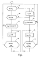
- the microprocessor 53 evaluates this situation via its signal inputs 56 and 57. He can according to the flowchart of FIG. 4 control the anti-trap 49.
- the program goes back to the beginning and goes through the checks cyclically. If, in the course of operation, the tension bar arrangement 25 starts against a resistance, the voltage drop across the sensor resistance 46 rises above the limit value 1. Thus, the query block 64 is exited to a following instruction block 65. Here, the power for the relay 48 is turned on, whereby the normally closed contact 47 is opened and the current through the motor 37 is interrupted.
- the microprocessor 53 checks whether the voltage on the line 51 has become equal to the voltage on the line 52, indicating that the user has shut down the window blind, or if the voltages on the lines 51 and 52 have previously been reversed, which means that the user wants to operate the blind in the sense of a retraction. If either condition is met, the program returns to the beginning, otherwise to the beginning of the instruction block 65. Thus, power to the motor 37 is forcibly turned off via the electrical pinch guard 45 until the user arbitrarily turns off the window blind, or in the sense of opening.
- the anti-pinch circuit shown is not only suitable for side window blinds, as they are explained with reference to FIGS. 1 and 2, but also for roof window blinds, as shown in Fig. 5, or for rear window blinds, as far as the operation of the tension rod assembly 25 as shown in FIG Fig. 2 takes place.
- the tension rod assembly 25 with the over the roller blind 19 laterally projecting guide arms 26 dives through the slot in the parcel shelf.
- the slot edges can act as a pair of scissors together with the laterally over the roller blind 19 projecting guide arms 26.
- An inevitable shutdown of the motor current in both directions of movement is therefore advisable.
- the gear motor When extended, the gear motor must operate against the action of the spring motor 42 and also overcome the frictional resistance of the thrust members 32 in the guide tubes or guide rails 29. When retracting, the conditions are reversed in that the spring motor 42 has a supporting effect.
- FIG. 4 the basic flowchart of FIG. 4 is expanded by a query block 67, in which it is checked whether the motor 37 receives a larger current in the reverse direction than is permissible according to a limit value II. If yes, an instruction block 68 is approached, which leads to the opening of the normally closed contact 47. This instruction block 68 is again executed until either the direction of rotation is reversed or the motor is switched off, which is checked in an instruction block 69.
- the monitoring of the instantaneous value of the motor current is provided.
- the instantaneous value of the motor current corresponds to the torque delivered by the motor.
- the current change dI / dt ie the derivative of the motor current after the time can be used.
- the program according to FIG. 4 thus remains unchanged, with the proviso that instead of the instantaneous value U 46, the differential of the voltage dU 46 / dt is used.
- the differentiating circuit can also be realized in software in the microprocessor 53.
- the electric motor 37 contains one or more Hall probes 70, as indicated by dashed lines in FIG. 3 by way of example.
- the flowchart of Fig. 3 changes to the effect that in place of U 46, the rotational speed n occurs.
- Fig. 5 shows a schematic view and a similar viewing angle of a section of a vehicle with a slightly different body shape, for the corresponding parts the same reference numerals as in Fig. 1 are used.
- the roof 2 includes a rectangular roof opening 71 by a corresponding roof window is housed.
- a roller blind 21 Below the roof cutout 71 is a roller blind 21, the free edge of a Extensible profile 72 is attached, which corresponds to the tension rod assembly 25 of FIG.
- the operation of the pull-out profile 72 is done via a similar mechanism as shown in Fig. 2.
- the winding shaft is located in the region of the vehicle rear edge of the roof cutout 71 while the guide rails 29 extend parallel to the side edges.
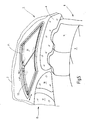
- Fig. 6 shows a rear window roller blind, in which the actuation of the roller blind is effected via two one-armed lever 75.
- the already mentioned winding shaft 22 is rotatably mounted in an elongated tubular housing 76. It is, as in the previous embodiments, biased by means of a spring motor in the sense of winding the blind sheet 21.
- a pull-out profile 77 At the free edge of the roller blind 21, i. the edge remote from the winding shaft is a pull-out profile 77, the function of the Switzerlandstaban extract 25 largely corresponds. It contains on the side facing the viewer grooves 78 which extend over the entire length of the extract profile. In these grooves slide the free ends of the two levers 75th
- the levers 75 are rotatably mounted on an output shaft 79 at its lower end.
- the output shaft 79 is part of an angular gear which is housed in a housing 81 and 82, respectively.
- the housings 81 and 82 are spaced apart from and fixed to the housing 76 as shown in the longitudinal direction.
- the output shafts 79 are parallel to each other.
- the arrangement is driven by the DC motor 37, for example, optionally displacing a worm contained in the gear housing 82 in revolutions. Via a coupling shaft 83, the motor 37 is also connected to the transmission contained in the transmission housing 81.
- Fig. 6 shows the rear window blind in the extended position.
- the levers 75 are in this position approximately at right angles to the longitudinal extent of the roller shaft 22.
- To retract the geared motor 37 is rotated with the corresponding direction in turns. This causes the two levers 75 to pivot towards each other, as a result of which the distance their free ends from the roller shaft 22 has decreases correspondingly.
- the coupled with the roller shaft 22 spring motor ensures that the roller blind 21 remains tensioned in any position of the lever 75.
- the retraction position is reached when the two levers 75 extend approximately parallel to the winding shaft 22.
- the blind housing 76 is located below the parcel shelf 14, as shown in Fig. 1.
- the roller blind moves through actuation by a slot contained in the rear shelf 14.
- the levers 75 are approximately parallel to the inside of the rear window 4.
Landscapes
- Engineering & Computer Science (AREA)
- Mechanical Engineering (AREA)
- Structural Engineering (AREA)
- Architecture (AREA)
- Civil Engineering (AREA)
- Operating, Guiding And Securing Of Roll- Type Closing Members (AREA)
- Power-Operated Mechanisms For Wings (AREA)
Applications Claiming Priority (1)
| Application Number | Priority Date | Filing Date | Title |
|---|---|---|---|
| DE102005030962A DE102005030962A1 (de) | 2005-04-21 | 2005-06-30 | Rollo mit elektrischem Einklemmschutz |
Publications (1)
| Publication Number | Publication Date |
|---|---|
| EP1739275A2 true EP1739275A2 (fr) | 2007-01-03 |
Family
ID=37027792
Family Applications (1)
| Application Number | Title | Priority Date | Filing Date |
|---|---|---|---|
| EP06001574A Withdrawn EP1739275A2 (fr) | 2005-06-30 | 2006-01-26 | Volet roulant avec dispositif anti-pincement éléctronique |
Country Status (5)
| Country | Link |
|---|---|
| US (1) | US20070000624A1 (fr) |
| EP (1) | EP1739275A2 (fr) |
| JP (1) | JP2007008463A (fr) |
| KR (1) | KR20070003618A (fr) |
| CN (1) | CN1891969A (fr) |
Families Citing this family (10)
| Publication number | Priority date | Publication date | Assignee | Title |
|---|---|---|---|---|
| ITTV20080004A1 (it) * | 2008-01-10 | 2009-07-11 | Nice Spa | Azionamento per avvolgibili con protezione contro vento eccessivo |
| JP4811618B2 (ja) * | 2009-06-29 | 2011-11-09 | 八千代工業株式会社 | サンルーフ装置 |
| CN102056362B (zh) * | 2009-11-04 | 2013-08-28 | 海洋王照明科技股份有限公司 | 一种车载灯具的控制电路及车载灯具 |
| JP5600484B2 (ja) * | 2010-06-09 | 2014-10-01 | 芦森工業株式会社 | シェード装置 |
| KR101323028B1 (ko) * | 2011-10-28 | 2013-10-29 | 주식회사 현대케피코 | 안티-핀치 시스템 제어 방법 및 이러한 방법을 사용하는 장치 |
| FR3024176B1 (fr) * | 2014-07-25 | 2016-08-05 | Somfy Sas | Procede de controle d'un actionneur d'enroulement, actionneur d'enroulement configure pour un tel procede et installation de fermeture ou de protection solaire comprenant un tel actionneur |
| DE102018116346A1 (de) * | 2018-07-05 | 2020-01-09 | Webasto SE | Abschattungsvorrichtung |
| DE102020101952B4 (de) * | 2020-01-28 | 2025-06-18 | Bayerische Motoren Werke Aktiengesellschaft | Verfahren zum Bereitstellen eines Einklemmschutzes für ein Kraftfahrzeug |
| CN115065805B (zh) * | 2022-05-24 | 2024-08-27 | 苏州海视德信息科技有限公司 | 一种便携式安全防控系统 |
| EP4640457A1 (fr) * | 2024-04-25 | 2025-10-29 | Inalfa Roof Systems Group B.V. | Ensemble store à rouleau |
Citations (2)
| Publication number | Priority date | Publication date | Assignee | Title |
|---|---|---|---|---|
| DE10057760A1 (de) | 2000-11-22 | 2002-06-06 | Bos Gmbh | Fensterrollo mit Zentriereinrichtung für den Zugstab |
| DE10351040B3 (de) | 2003-10-31 | 2005-05-25 | Bos Gmbh & Co. Kg | Fensterrollo für Kraftfahrzeuge und Seitenverkleidung mit integrierter Führungsschiene |
Family Cites Families (19)
| Publication number | Priority date | Publication date | Assignee | Title |
|---|---|---|---|---|
| ZA847740B (en) * | 1983-10-12 | 1985-05-29 | Byrne & Davidson Ind Ltd | Obstruction detection means |
| JPS60115784A (ja) * | 1983-11-28 | 1985-06-22 | アイシン精機株式会社 | 開口覆材の自動開閉装置 |
| DE3612165A1 (de) * | 1986-04-11 | 1987-10-22 | Baumeister & Ostler | Fuehrungsloses fensterrollo, insbesondere fuer kraftfahrzeuge |
| US4831509A (en) * | 1986-04-16 | 1989-05-16 | Byrne & Davidson Doors (N.S.W.)Pty. Limited | Door operation control apparatus |
| US5585705A (en) * | 1994-05-05 | 1996-12-17 | Leopold Kostal Gmbh & Co. Kg | Process for monitoring movement of closure devices which may be adjusted by motors |
| KR0171240B1 (ko) * | 1994-05-17 | 1999-05-01 | 가다오까 마사다까 | 차량탑재용 모터구동장치 |
| US5483135A (en) * | 1994-06-06 | 1996-01-09 | Ford Motor Company | Adaptive system and method for controlling vehicle window operation |
| DE4440449C2 (de) * | 1994-11-14 | 1997-06-12 | Elero Antrieb Sonnenschutz | Verfahren und Vorrichtung zur Stillstandssteuerung von elektromotorisch betriebenen Rolläden oder dergleichen |
| DE59610883D1 (de) * | 1995-10-28 | 2004-02-05 | Elero Gmbh | Verfahren zum Antreiben von elektromotorisch betriebenen Markisen oder dergleichen |
| US5585702A (en) * | 1995-11-03 | 1996-12-17 | Itt Automotive Electrical Systems, Inc. | Auto up window with osbtacle detection system |
| JPH1162380A (ja) * | 1997-08-22 | 1999-03-05 | Alps Electric Co Ltd | パワーウインド装置の挟み込み検知方法 |
| US6051945A (en) * | 1999-01-25 | 2000-04-18 | Honda Giken Kogyo Kabushiki Kaisha | Anti-pinch safety system for vehicle closure device |
| DE19908658A1 (de) * | 1999-02-27 | 2000-08-31 | Bosch Gmbh Robert | Schließvorrichtung mit Sicherheitsfunktion |
| DE10052042A1 (de) * | 2000-10-20 | 2002-05-16 | Bos Gmbh | Antriebssystem für rollbare Abdeckeinrichtungen von Kraftfahrzeugen |
| DE10057762A1 (de) * | 2000-11-22 | 2002-06-06 | Bos Gmbh | Fensterrollo mit Ausgleich gegen Verzug |
| EP1379925A1 (fr) * | 2001-03-15 | 2004-01-14 | Stoneridge Control Devices, Inc. | Actionneur electro-mecanique avec moteur sans balai a courant continu avec protection contre les pincements |
| WO2003023932A1 (fr) * | 2001-09-13 | 2003-03-20 | Siemens Vdo Automotive Corporation | Systeme de detection de coincement |
| US6906487B2 (en) * | 2002-01-21 | 2005-06-14 | International Rectifier Corporation | Anti-pinch window drive circuit |
| JP3907195B2 (ja) * | 2003-09-02 | 2007-04-18 | 矢崎総業株式会社 | パワーウインド挟み込み防止装置 |
-
2006
- 2006-01-26 EP EP06001574A patent/EP1739275A2/fr not_active Withdrawn
- 2006-04-10 US US11/401,052 patent/US20070000624A1/en not_active Abandoned
- 2006-06-29 JP JP2006180051A patent/JP2007008463A/ja not_active Withdrawn
- 2006-06-29 KR KR1020060059170A patent/KR20070003618A/ko not_active Withdrawn
- 2006-06-29 CN CNA2006100996588A patent/CN1891969A/zh active Pending
Patent Citations (2)
| Publication number | Priority date | Publication date | Assignee | Title |
|---|---|---|---|---|
| DE10057760A1 (de) | 2000-11-22 | 2002-06-06 | Bos Gmbh | Fensterrollo mit Zentriereinrichtung für den Zugstab |
| DE10351040B3 (de) | 2003-10-31 | 2005-05-25 | Bos Gmbh & Co. Kg | Fensterrollo für Kraftfahrzeuge und Seitenverkleidung mit integrierter Führungsschiene |
Also Published As
| Publication number | Publication date |
|---|---|
| US20070000624A1 (en) | 2007-01-04 |
| JP2007008463A (ja) | 2007-01-18 |
| KR20070003618A (ko) | 2007-01-05 |
| CN1891969A (zh) | 2007-01-10 |
Similar Documents
| Publication | Publication Date | Title |
|---|---|---|
| EP1211110B1 (fr) | Store à enrouler avec compensation contre déformation | |
| EP1666291B1 (fr) | Store à enrouler de fenêtre avec montage simplifié | |
| EP1468854B1 (fr) | Store à enrouleur pour vitres latérales | |
| DE10057764B4 (de) | Fensterrollo mit variabler Abschattungswirkung | |
| EP1211109B1 (fr) | Store à enrouler avec dispositif de centrage pour la tige de tension | |
| EP1886853B1 (fr) | Store de fenêtre doté d'un actionnement par le lève-glace | |
| EP1182066B1 (fr) | Véhicule avec store à enrouleur dans le toit | |
| EP1123825B9 (fr) | Store à enrouleur pour fenêtre arrière | |
| EP2039547B1 (fr) | Store de fenêtre latérale doté d'une aide à l'introduction | |
| EP2060421B1 (fr) | Agencement de store doté d'un entraînement à friction réduite | |
| EP1782979B1 (fr) | Store à enrouleur sans lacune pour une lunette arrière | |
| DE102007063705B4 (de) | Rollo mit Lochbandantrieb | |
| EP1533158B1 (fr) | Système de store à enrouleur pour vitres latérals pourvu d'un pièce de contour de vitre | |
| DE102007012281A1 (de) | Automatisch betätigbares Seitenfensterrollo | |
| EP1619057B1 (fr) | Agencement de store pare-soleil pour vitre latérale | |
| DE10052042A1 (de) | Antriebssystem für rollbare Abdeckeinrichtungen von Kraftfahrzeugen | |
| EP1724137B1 (fr) | Store à enroulement pour fenêtre avec rouleau axialement réglable | |
| EP1739275A2 (fr) | Volet roulant avec dispositif anti-pincement éléctronique | |
| EP1714813A2 (fr) | Store enroulable avec dispositif anti-coincement | |
| DE102007004665B4 (de) | Fensterrollo mit Antrieb über den Fensterhebermotor | |
| DE202007015602U1 (de) | Elektrisches Seitenfensterrollo | |
| DE202005020693U1 (de) | Rollo mit elektrischem Einklemmschutz | |
| DE102005030962A1 (de) | Rollo mit elektrischem Einklemmschutz | |
| EP1738942A2 (fr) | Store à enrouleur pour véhicule automobile muni d'une butée de contact fixée rigidement sur un actionneur | |
| DE10227514B4 (de) | Fahrzeugdach mit einem Dachöffnungssystem und einer zwangsgesteuerten verstellbaren Abschattungseinrichtung |
Legal Events
| Date | Code | Title | Description |
|---|---|---|---|
| PUAI | Public reference made under article 153(3) epc to a published international application that has entered the european phase |
Free format text: ORIGINAL CODE: 0009012 |
|
| AK | Designated contracting states |
Kind code of ref document: A2 Designated state(s): AT BE BG CH CY CZ DE DK EE ES FI FR GB GR HU IE IS IT LI LT LU LV MC NL PL PT RO SE SI SK TR |
|
| AX | Request for extension of the european patent |
Extension state: AL BA HR MK YU |
|
| STAA | Information on the status of an ep patent application or granted ep patent |
Free format text: STATUS: THE APPLICATION IS DEEMED TO BE WITHDRAWN |
|
| 18D | Application deemed to be withdrawn |
Effective date: 20100202 |