EP1743384B1 - Reseau del possedant des detecteurs del fonctionnant sur la base sur ce reseau - Google Patents
Reseau del possedant des detecteurs del fonctionnant sur la base sur ce reseau Download PDFInfo
- Publication number
- EP1743384B1 EP1743384B1 EP05742823.7A EP05742823A EP1743384B1 EP 1743384 B1 EP1743384 B1 EP 1743384B1 EP 05742823 A EP05742823 A EP 05742823A EP 1743384 B1 EP1743384 B1 EP 1743384B1
- Authority
- EP
- European Patent Office
- Prior art keywords
- array
- light
- detector
- emitting diodes
- diode
- Prior art date
- Legal status (The legal status is an assumption and is not a legal conclusion. Google has not performed a legal analysis and makes no representation as to the accuracy of the status listed.)
- Expired - Lifetime
Links
- 239000004065 semiconductor Substances 0.000 claims description 73
- 238000000034 method Methods 0.000 claims description 18
- 238000004519 manufacturing process Methods 0.000 claims description 8
- 230000001678 irradiating effect Effects 0.000 claims description 6
- 230000004044 response Effects 0.000 claims description 6
- 238000012544 monitoring process Methods 0.000 description 33
- 238000001816 cooling Methods 0.000 description 25
- 230000003287 optical effect Effects 0.000 description 19
- 230000008878 coupling Effects 0.000 description 18
- 238000010168 coupling process Methods 0.000 description 18
- 238000005859 coupling reaction Methods 0.000 description 18
- 230000005855 radiation Effects 0.000 description 14
- 238000001514 detection method Methods 0.000 description 13
- 230000006870 function Effects 0.000 description 11
- 239000000463 material Substances 0.000 description 9
- 238000005259 measurement Methods 0.000 description 9
- 238000003491 array Methods 0.000 description 7
- 238000012512 characterization method Methods 0.000 description 7
- 239000000835 fiber Substances 0.000 description 7
- 230000035945 sensitivity Effects 0.000 description 7
- 238000010586 diagram Methods 0.000 description 5
- 238000011156 evaluation Methods 0.000 description 5
- 238000012545 processing Methods 0.000 description 5
- 238000013459 approach Methods 0.000 description 4
- 238000005513 bias potential Methods 0.000 description 4
- 230000008859 change Effects 0.000 description 4
- 238000005516 engineering process Methods 0.000 description 4
- 238000005286 illumination Methods 0.000 description 4
- 230000003595 spectral effect Effects 0.000 description 4
- 239000000758 substrate Substances 0.000 description 4
- XUIMIQQOPSSXEZ-UHFFFAOYSA-N Silicon Chemical compound [Si] XUIMIQQOPSSXEZ-UHFFFAOYSA-N 0.000 description 3
- 230000003750 conditioning effect Effects 0.000 description 3
- 230000006378 damage Effects 0.000 description 3
- 238000010438 heat treatment Methods 0.000 description 3
- 230000007246 mechanism Effects 0.000 description 3
- 229910052710 silicon Inorganic materials 0.000 description 3
- 239000010703 silicon Substances 0.000 description 3
- 230000009885 systemic effect Effects 0.000 description 3
- 230000008901 benefit Effects 0.000 description 2
- 238000009529 body temperature measurement Methods 0.000 description 2
- 230000015556 catabolic process Effects 0.000 description 2
- 238000006731 degradation reaction Methods 0.000 description 2
- 230000004907 flux Effects 0.000 description 2
- 230000007774 longterm Effects 0.000 description 2
- 238000012986 modification Methods 0.000 description 2
- 230000004048 modification Effects 0.000 description 2
- 230000008569 process Effects 0.000 description 2
- 230000009467 reduction Effects 0.000 description 2
- 238000013403 standard screening design Methods 0.000 description 2
- 238000012360 testing method Methods 0.000 description 2
- 238000012795 verification Methods 0.000 description 2
- 230000001133 acceleration Effects 0.000 description 1
- 230000009471 action Effects 0.000 description 1
- 238000004458 analytical method Methods 0.000 description 1
- 230000003466 anti-cipated effect Effects 0.000 description 1
- 230000005540 biological transmission Effects 0.000 description 1
- 238000006243 chemical reaction Methods 0.000 description 1
- 239000011248 coating agent Substances 0.000 description 1
- 238000000576 coating method Methods 0.000 description 1
- 239000012809 cooling fluid Substances 0.000 description 1
- 230000023077 detection of light stimulus Effects 0.000 description 1
- 230000002708 enhancing effect Effects 0.000 description 1
- 230000006872 improvement Effects 0.000 description 1
- 230000003993 interaction Effects 0.000 description 1
- 238000001459 lithography Methods 0.000 description 1
- 238000007726 management method Methods 0.000 description 1
- 238000013507 mapping Methods 0.000 description 1
- 238000012806 monitoring device Methods 0.000 description 1
- 239000013307 optical fiber Substances 0.000 description 1
- 230000002093 peripheral effect Effects 0.000 description 1
- 238000007639 printing Methods 0.000 description 1
- 238000002310 reflectometry Methods 0.000 description 1
- 230000000717 retained effect Effects 0.000 description 1
- 239000013077 target material Substances 0.000 description 1
Images


Classifications
-
- H—ELECTRICITY
- H05—ELECTRIC TECHNIQUES NOT OTHERWISE PROVIDED FOR
- H05B—ELECTRIC HEATING; ELECTRIC LIGHT SOURCES NOT OTHERWISE PROVIDED FOR; CIRCUIT ARRANGEMENTS FOR ELECTRIC LIGHT SOURCES, IN GENERAL
- H05B45/00—Circuit arrangements for operating light-emitting diodes [LED]
- H05B45/10—Controlling the intensity of the light
- H05B45/12—Controlling the intensity of the light using optical feedback
-
- H—ELECTRICITY
- H05—ELECTRIC TECHNIQUES NOT OTHERWISE PROVIDED FOR
- H05B—ELECTRIC HEATING; ELECTRIC LIGHT SOURCES NOT OTHERWISE PROVIDED FOR; CIRCUIT ARRANGEMENTS FOR ELECTRIC LIGHT SOURCES, IN GENERAL
- H05B45/00—Circuit arrangements for operating light-emitting diodes [LED]
- H05B45/10—Controlling the intensity of the light
- H05B45/18—Controlling the intensity of the light using temperature feedback
-
- H—ELECTRICITY
- H05—ELECTRIC TECHNIQUES NOT OTHERWISE PROVIDED FOR
- H05B—ELECTRIC HEATING; ELECTRIC LIGHT SOURCES NOT OTHERWISE PROVIDED FOR; CIRCUIT ARRANGEMENTS FOR ELECTRIC LIGHT SOURCES, IN GENERAL
- H05B45/00—Circuit arrangements for operating light-emitting diodes [LED]
- H05B45/40—Details of LED load circuits
- H05B45/44—Details of LED load circuits with an active control inside an LED matrix
- H05B45/46—Details of LED load circuits with an active control inside an LED matrix having LEDs disposed in parallel lines
Definitions
- Light-emitting semiconductor devices may be arranged in various configurations, such as arrays, for lighting applications. These applications generally have associated parameters (e.g., a photoreaction may entail provision of one or more levels of radiant power, at one or more wavelengths, applied over one or more periods of time). In these applications, the light emitting semiconductor devices generally are employed to provide radiant output and otherwise operate in accordance with various, desired characteristics, e.g., temperature, spectral distribution and radiant power. At the same time, the light emitting semiconductor devices typically have certain operating specifications, which specifications generally are associated with the light emitting semiconductor devices' fabrication and, among other things, are directed to preclude destruction andlor forestall degradation of the devices. These specifications generally include operating temperatures and applied, electrical power.
- Arrays of light emitting semiconductor devices have been constructed which provide for monitoring selected of the array's characteristics. Providing such monitoring enables verification of the array's proper operation and, in turn, determination as to whether the array is operating in any way other than properly. An array may be operating improperly with respect to either/both the application's parameters or/and the array's specifications.
- Monitoring also supports control of an array's operation. Control, in turn, may be employed to enable and/or enhance the array's proper operation and/or performance of the application. Monitoring the array's operating temperature and radiant output supports control of the array, directly or indirectly, including through adjustment(s) in applied power and cooling (such as through a systemic cooling system). This control may be employed to enable and/or enhance balance between the array's radiant output and its operating temperature, so as, e.g., to preclude heating the array beyond its specifications.
- control of the array in enabling/enhancing performance of an application may be illustrated via example.
- an array is used that is understood to include light emitting diodes (LEDs).
- the application is understood to require provision, in sequence, of light in the red, then green and then blue spectral, at three respective energy levels, while maintaining a select temperature range relating to the work piece.
- control may again be directed to the array's applied power and to cooling, e.g., by a systemic cooling system.
- the control is again responsive to the monitoring of the array's operating temperature and radiant output. With this monitoring, the system is enabled to sense the energy applied to the work piece for the first wavelength, compare that energy to the respective energy level, while continually monitoring the temperature.
- control may be employed to increase cooling, to decrease the radiant power, or both, while continuing to gauge the applied energy. Once the energy level for the first wavelength is reached, control powers off the LEDs associated with the first wavelength and powers on the LEDs associated with the next sequential wavelength, and so on.
- Conventional approaches for monitoring and controlling an array typically propose to mount detectors around the array's perimeter or otherwise proximate to, but separate from the array. In doing so, the detectors detect radiant output or temperature associated with the whole, or relatively large portions of, the array. Moreover, responsive to such detection, the array generally is controlled as a whole, or in relatively large portions. Also, conventional industry approaches may use various detectors, alone or in combination: in some cases, only photo detectors are used; in other cases, only temperature sensors are used; in still other cases, both photo detectors and temperature sensors are used and, in still other cases, some other combination of detectors is used.
- the ⁇ 148 Patent generally, proposes to monitor and control a traffic signal's LED array using a single LED light detector, together with a controller, wherein the LED light detector is disposed proximate to the array (but not part of the array) so as to measure the luminous output of (i) one or more of the array's LEDs or (ii) a so-called “sample” LED which is not part of the array, but performs similarly.
- the '148 Patent proposes that the controller provide for selection from among a plurality of taps of a transformer, thereby adjusting the voltage applied to the LED array as a whole and maintaining the luminous output of the traffic signal's LED array.
- the '148 Patent also proposes (a) provision of a measurement device for measuring the temperature of the LED array generally, (b) selection of a tap responsive to such measurement and (c) associated adjustment of the voltage applied to the LED array as a whole.
- U.S. Patent No. 6,683,421, to Kennedy et al. entitled Addressable Semiconductor Array Light Source For Localized Radiation Delivery (the "'421 Patent"), the contents of which are hereby incorporated by reference as if recited in full herein, for all purposes.
- the '421 Patent proposes to monitor and control a photoreaction device that includes a LED array, a photo sensor and a temperature sensor.
- the photo sensor is proposed to preferably comprise semiconductor photodiodes that provide continuous monitoring of the light energy delivered to a work piece, so that irradiation may be controlled.
- the LED array is proposed to have an associated output window positioned above the LED array.
- the output window is proposed to be selected so that a small percentage of the LED array's light energy (typically less than 10%) is internally reflected within the window.
- This internally reflected light is proposed to be measured by the photo sensor. Not only is this reflected light measured, it is expressly specified that this configuration minimizes or prevents light energy reflected from the work piece or from external sources from being detected by the photo sensor.
- the photo sensor is proposed to be positioned and configured for that function, e.g., using a series of photo sensors positioned around the perimeter of the output window. Moreover, it is expressly specified that this measurement using the series of photo sensors will detect changes in average optical power.
- This embodiment has disadvantages.
- only average optical power is detected. That is, the window captures the internally reflected light from the entire array, which captured light is provided to the sensors. Accordingly, the sensors cannot determine where the LED array's radiant output may be improper and, as such, cannot make adjustments except across the entire array.
- control based on such light energy is precluded.
- the 421 Patent proposes to employ optical fibers between columns of LEDs in the array.
- the '421 Patent proposes that these fibers, preferably, will be made of material which is able to receive sidewall light emissions from the LEDs of the adjacent column of the LED array.
- the '421 Patent further proposes that, as to each fiber, the received sidewall light emissions are directed through internal reflection toward a respective photo sensor, the photo sensor being positioned at the perimeter of fhe array, disposed at the end of the fiber.
- each photo sensor will measure such light, detecting changes in average optical power.
- This embodiment has disadvantages. Again, only an average optical power is detected. Average optical power is again understood in that each fiber captures internally reflected light from the plurality of LEDs disposed across an entire dimension of the array, which captured light is provided to the respective sensor. The respective sensor cannot determine where the LED array's radiant output may be improper across the implicated dimension and, as such, cannot make adjustments except across the entire set of LEDs associated with that fiber.
- the fibers are disposed among the LEDs, in the plane of the array (i.e., so as to capture sidewall light emissions), use of the fibers precludes or degrades use of optics that, desirable, collect and collimate all or substantially all of the radiant output of each LED (such optics include,.e.g., a grid of reflectors as proposed by the '421 Patent or a plurality of micro-reflectors in which individual LEDs are mounted, preferably on a one-to-one basis).
- optics include,.e.g., a grid of reflectors as proposed by the '421 Patent or a plurality of micro-reflectors in which individual LEDs are mounted, preferably on a one-to-one basis.
- the '421 Patent proposes to position about a LED array a temperature sensor and a plurality of photo detectors.
- the ⁇ 421 Patent omits to describe the disposition of the temperature sensor or the photo detectors relative to the plane of the LED array.
- the photo detectors are positioned above the array in association with a light guide, e.g., an output window. This inference follows as the '421 Patent expressly specifies that the LED die are arranged in a shape approximating a "filled square", which arrangement would leave no space for the temperature sensor or the photo detectors in the plane of the LED array.
- disadvantages include those set out above respecting other embodiments using light guide(s) to collect detected output radiation.
- a sensor or photo detector were placed in the LED array's plane, the sensor or detector would be disposed between the rows and columns of the LED array, contemplating having substantial space between the LEDs of the array. Such space generally is not desirable (i.e., typically, it is desirable to employ densely-packed LED arrays, wherein space between rows and columns of LEDs typically is insufficient to accept interposition of a semiconductor device, such as conventionally-sized sensor or detector).
- the 421 Patent proposes to group the LEDs of the array into alternating rows, such that the odd rows would form one group and the even rows would form a second group.
- the ⁇ 421 Patent further proposes that the odd rows would be energized as a group to emit light energy, including sidewall light emissions, and that the even rows would function, as a group, as a photo sensor (i.e., by generating a current proportional to the intensity of the impinging sidewall light emissions from the one group of odd rows).
- the '421 Patent further proposes that the respective functions of the odd and even rows may be switched, so that the odd rows operate as the detecting group, while the even rows operate as the emitting group.
- Average optical power is detected.
- Average optical power is again understood in that the detecting LEDs, as a group, detect the sidewall light emissions from the emitting group, which emitting group includes all the LEDs of all non-detecting rows of the entire array.
- the detecting group of LEDs cannot determine where the LED array's radiant output may be improper across any one or more rows of the emitting group and, as such, cannot make adjustments except for the entire group of emitting LEDs.
- control based on detecting other light energy associated with the array is precluded.
- the present invention provides an optical device that utilizes at least one semiconductor device to measure selected operational characteristics of the optical device such as the radiant output of the array and the temperature of the array.
- one or more detector diodes are positioned within the array to measure the radiant output and/or the heat at one or more selected locations within the array.
- the detector diodes operate in different modes to measure radiant output and temperature so that in a first mode the detector diodes are selected to measure radiant output and in a second mode the detector diodes are selected to measure temperature.
- the present invention provides an optical system that includes an array of semiconductor devices for performing an operation in which the semiconductor devices have multiple characteristics associated with performing the operation. At least one detector is located within the array to selectively monitor multiple characteristics of the semiconductor devices and is configured to generate a signal corresponding to the selected characteristic. A controller is configured to control the semiconductor devices in response to the signal from the detector.
- the present invention further provides an optical system having an array of semiconductor devices for performing an operation in which the semiconductor devices having multiple characteristics associated with performing the operation where at least one of the multiple characteristics is concentrated at an area of the array.
- At least one detector is located within the array at the area of the array to selectively monitor multiple characteristics of the semiconductor devices. The detector is configured to generate a signal corresponding to the selected characteristic.
- a controller. is configured to control the semiconductor devices in response to the signal from the detector.
- the present invention further provides an optical system having an array of semiconductor devices for performing an operation and at least one thermal diode located within the array to monitor heat generated by the semiconductor devices.
- a controller is configured to control the semiconductor devices in response to the signal from the at least one thermal diode.
- the present invention further provides a method of controlling an optical system by providing an array of semiconductor devices for performing an operation, the semiconductor devices having multiple characteristics associated with performing the operation, providing at least one detector located within the array to selectively monitor multiple characteristics of the semiconductor devices, the detector configured to generate a signal corresponding to the selected characteristic and providing a controller configured to control the semiconductor devices in response to the signal from the detector.
- the present invention further provides an optical system that includes an array of semiconductor devices wherein the array includes one or more semiconductor devices that are electrically coupled to act as a detector.
- Utilizing detector diodes in the array to measure optical power and temperature has several advantages.
- One advantage is that the duty cycle and variance in the radiant intensity of the emitting array is substantially unaffected.
- Power monitoring and temperature sensing can be accomplished by providing the appropriate electronic circuitry to variably bias the proper diodes with additional circuitry to monitor the photocurrent. Therefore, using some of the diodes as photodetectors and temperature sensors provides a very efficient means of power monitoring and temperature sensing.
- locating detector diodes within the array provides an ideal location for monitoring power and temperature.
- FIG. 1 is a block diagram of a photoreactive system 10 in accordance with the invention.
- the photoreactive system 10 comprises a light emitting subsystem 12, a controller 14, a power source 16 and a cooling subsystem 18.
- the light emitting subsystem 12 preferably comprises a plurality of semiconductor devices 19. Selected of the plurality of semiconductor devices 19 are implemented to provide radiant output 24. The radiant output 24 is directed to a work piece 26. Returned radiation 28 may be directed back to the light emitting system 12 from the work piece 26 (e.g., via reflection of the radiant output 24).
- the radiant output 24 preferably is directed to the work piece 26 via coupling optics 30.
- the coupling optics 30, if used, may be variously implemented.
- the coupling optics may include one or more layers, materials or other structure interposed between the semiconductor devices 19 providing radiant output 24 and the work piece 26.
- the coupling optics 30 may include a micro-lens array to enhance collection, condensing, collimation or otherwise the quality or effective quantity of the radiant output 24.
- the coupling optics 30 may include a micro-reflector array. In employing such micro-reflector array, each semiconductor device providing radiant output 24 preferably is disposed in a respective micro-reflector, on a one-to-one basis.
- each of the layers, materials or other structure have a selected index of refraction.
- each index of refraction By properly selecting each index of refraction, reflection at interfaces between layers, materials and other structure in the path of the radiant output 24 (and/or returned radiation 28) may be selectively controlled.
- reflection at that interfaces may be reduced, toward being eliminated or, at least, minimized, so as to enhance the transmission of radiant output at that interface for ultimate delivery to the work piece 26.
- Control of indexes of refraction so as to enhance radiant output is shown and described in U.S. Patent Application No._, filed March 18, 2005 (Attorney Docket No. PHO-2.009.US), entitled “DIRECT COOLING OF LEDS", which application claims priority from U.S. Provisional Application Serial Number 60/554,632, filed March 18, 2004 .
- the coupling optics 30 may be employed for various purposes.
- Example purposes include, among other s, to protect the semiconductor devices 19, to retain cooling fluid associated with the cooling subsystem 18, to collect, condense and/or collimate the radiant output 24, to collect, direct or reject returned radiation 28, or for other purposes, alone or in combination.
- Selected of the plurality of semiconductor devices 19 preferably are coupled to the controller 14 via coupling electronics 22, so as to provide data to the controller 14.
- the controller is preferably also implemented to control such data-providing semiconductor devices, e.g., via the coupling electronics 22.
- the controller 14 preferably is also connected to, and is implemented to control, each of the power source 16 and the cooling subsystem 18. Moreover, the controller 14 preferably receives data from respective such source 16 and subsystem 18.
- controller 14 may also be connected to, and implemented to control, further elements 32, 34.
- Element 32 is internal of the photoreactive system 10.
- Element 34 is external of the photoreactive system 10, but is understood to be associated with the work piece 26 (e.g., handling, cooling or other external equipment) or to be otherwise related to the photoreaction the system 10 supports.
- the data received by the controller 14 from one or more of the power source 16, the cooling subsystem 18, the light emitting subsystem 12, and/or elements 32, 34 may be of various types.
- the data may be representative of one or more characteristics associated with coupled semiconductor devices 19, respectively.
- the data may be representative of one or more characteristics associated with the respective component 12, 16, 18, 32, 34 providing the data.
- the data may be representative of one or more characteristics associated with the work piece 26 (e.g., representative of the radiant outputs energy or spectral component(s) directed to the work piece).
- the data may be representative of some combination of these characteristics.
- the controller 14 is implemented to control one or more of the power source 16, cooling subsystem 18, light emitting subsystem 12 (including one or more such coupled semiconductor devices), and/or the elements 32, 34.
- the controller 14 may be implemented to either (a) increase the power source's supply of power to one or more of the semiconductor devices, (b) increase cooling of the light emitting subsystem via the cooling subsystem 18 (i.e., certain light emitting devices, if cooled, provide greater radiant output), (c) increase the time during which the power is supplied to such devices, or (d) a combination of the above.
- the cooling subsystem 18 is implemented to manage the thermal behavior of the light emitting subsystem 12. That is, generally, the cooling subsystem 18 provides for cooling of such subsystem 12 and, more specifically, the semiconductor devices 19.
- the cooling subsystem 18 may also be implemented to cool the work piece 26 and/or the space between the piece 26 and the photoreactive system 10 (e.g., particularly, the light emitting subsystem 12). Cooling systems providing thermal management in photoreactive systems generally and as to light emitting semiconductor devices in particular are shown and described in U.S. Patent Application No., filed March 18, 2005 (Attorney Docket No. PHO-2.009.US), as previously described above.
- the photoreactive system 10 may be used for various applications. Examples include, without limitation, curing applications ranging from ink printing to the fabrication of DVDs and lithography. Generally, the applications in which the photoreactive system 10 is employed have associated parameters. That is, an application may contemplate parameters as follows: provision of one or more levels of radiant power, at one or more wavelengths, applied over one or more periods of time. In order to properly accomplish the photoreaction associated with the application, optical power may need to be delivered at or near the work piece at or above a one or more predetermined levels (and/or for a certain time, times or range of times).
- the semiconductor devices 19 providing radiant output 24 generally are to operated in accordance with various characteristics associated with the application's parameters, e.g., temperature, spectral distribution and radiant power.
- the semiconductor devices 19 topically have certain operating specifications, which specifications generally are associated with the semiconductor devices' fabrication and, among other things, should be followed in order to preclude destruction and/or forestall degradation of the devices.
- Other components of the system 10 also typically have associated operating specifications. These specifications generally include ranges (e.g., maximum and minimum) for operating temperatures and applied, electrical power.
- the photoreactive system 10 supports monitoring of the application's parameters.
- the photoreactive system 10 preferably provides for monitoring of the semiconductor devices 19, including as to respective characteristics and specifications.
- the photoreactive system 10 preferably also provides for monitoring of the selected other components of the system 10, including as to respective characteristics and specifications.
- Providing such monitoring enables verification of the system's proper operation and, in turn, determination as to whether the system 10 is operating in any way other than properly.
- the system 10 may be operating improperly with respect to either/both the application's parameters, any components characteristics associated with such parameters and/or any component's respective operating specifications.
- the provision of monitoring is contemplated above, with respect to the descriptions of data provided to the controller 14 by one or more of the system's components.
- Monitoring also supports control of the system's operation.
- control is implemented via the controller 14 receiving and being responsive to data from one or more system components.
- This control may be implemented directly (i.e., by controlling a component through control signals directed to the component, based on data respecting that components operation) or indirectly (i.e., by controlling a component's operation through control signals directed to adjust operation of other components).
- the semiconductor device's radiant output is adjusted indirectly through control signals directed to the power source 16 that adjust power applied to the light emitting subsystem 12 and/or through control signals directed to the cooling subsystem 18 that adjust cooling applied to the light emitting subsystem 12.
- Control preferably is employed to enable and/or enhance the system's proper operation and/or performance of the application.
- control may also be employed to enable and/or enhance balance between the array's radiant output and its operating temperature, so as, e.g., to preclude heating the array beyond its specifications while also directing radiant energy to the work piece 26 sufficient to properly complete the photoreaction(s) of the application.
- the subsystem 12 may be implemented using an array of light emitting semiconductor devices 19.
- the subsystem 12 may be implemented using a high-density, light emitting diode (LED) array.
- LED light emitting diode
- LED arrays may be used and are described in detail herein, it is understood that the semiconductor devices 19, and array(s) 20 of same, may be implemented using other light emitting technologies without departing from the principles of the invention, which technologies include, without limitation, organic LEDs, laser diodes, other semiconductor lasers.
- the plurality of semiconductor devices 19 may be provided in the form of an array 20.
- the array 20 preferably is implemented so that one or more (and, preferably, most) of the semiconductor devices 19 are implemented to provide radiant output.
- one or more of the array's semiconductor devices 19 are implemented so as to provide for monitoring selected of the array's characteristics.
- the monitoring devices are selected from among the devices in the array and, generally, have the same structure as the other, emitting devices.
- the difference between emitting and monitoring is determined by the coupling electronics 22 associated with the particular semiconductor device (e.g., in a basic form, a LED array has monitoring LEDs where the coupling electronics provides a reverse current while having emitting LEDs where the coupling electronics provides a forward current).
- selected of the semiconductor devices in the array may be either/both multifunction devices and/or multimode devices, where (a) multifunction devices are capable of detecting more than one characteristic (e.g., either radiant output, temperature, magnetic fields, vibration, pressure, acceleration, and other mechanical forces or deformations) and is switched among these detection functions in accordance with the application parameters or other determinative factors and (b) multimode devices are capable of emission, detection and some other mode (e.g., off) and are switched among modes in accordance with the application parameters or other determinative factors.
- multifunction devices are capable of detecting more than one characteristic (e.g., either radiant output, temperature, magnetic fields, vibration, pressure, acceleration, and other mechanical forces or deformations) and is switched among these detection functions in accordance with the application parameters or other determinative factors
- multimode devices are capable of emission, detection and some other mode (e.g., off) and are switched among modes in accordance with the application parameters or other determinative factors.
- Figure 2 illustrates one embodiment of an array 20 of semiconductor devices 19, having a set of semiconductor devices 19, at selected positions within the array 20, implemented to perform as detectors, monitoring selected characteristic(s).
- the selected characteristic(s) may be any one or more of radiant output, temperature or such other characteristic to which the semiconductor device is sensitive.
- the remaining devices 19 are implemented to provide radiant output.
- the semiconductor devices 19 comprise LEDs.
- the emitting semiconductor devices 19 generally are forward biased.
- Each detector 36 generally, is sensitive to its respective, selected characteristic, providing a signal or other data representative of the detected characteristic. This data may be provided to the coupling electronics 22 for further conditioning or other processing. In any case, data is ultimately provided to the controller 14 which data is either as detected or subject to such or some other conditioning or processing.
- a set of detectors may be variously defined.
- criteria of a set may be defined to include one or more of: the characteristic(s) detected; whether any of the detectors are multifunction or multimode and, if so the when and/or under what circumstances these detectors switch functions and/or modes; as to detectors that are not multifunction, which detector(s) detect which characteristic(s); the total number of detectors and the detectors' positions within the array; dispositions relative to one another; any dynamic characteristics associated with detection (e.g., detection timing(s) diagrams relative to the application's progress).
- detectors may be patterned or grouped, based on convenience, economies, efficiencies, performance, or otherwise, all with or without consideration of any specific application. Patterns can be, e.g., generated randomly or pseudo-randomly, which generation may be done separately by the type of detector or for all employed detectors at once.
- the set of detectors 36 may be defined based on characterization of the specific application using the photoreactive system 10. Characterization is generally known in engineering. Characterization may be variously achieved, including via experience (e.g., running trials and studying/testing the results at selected steps throughout the application), modeling (e.g., computerized emulation, etc.), theoretical analysis (e.g., hitting the books), and otherwise, alone or in selected combinations. Characterization may be performed statically or dynamically, including during production runs of the application.
- Characterization in defining the set of detectors 36 and otherwise the implementation and use of the photoreactive system 10, is preferably used to identify sensitivities relating to the specific application.
- the identified sensitivities may arise at various steps or times in the application, and may be directed to various components of the system 10 and, in turn, to various parts of the components.
- sensitivities may be expected relating to the work piece 26 and/or the array 20.
- the sensitivities may be hot spots, areas of over or under exposure, or other areas of the work piece subject to photoreaction, each of which area will tend to be vulnerable to improper processing unless detected and controlled.
- the sensitivities may be a hot spot that will tend to cause either improper processing (e.g., inadequate radiant output due to heating) or result in damage to the array (e.g., by operating outside the semiconductor devices' specifications), unless detected and controlled.
- knowing the sensitivities enables implementing a responsively defined set of detectors 36 (e.g., to detect the characteristic at or proximate the area of sensitivity), with proper control following straightforwardly from detection.
- Characterization in defining the set of detectors 36 and otherwise the implementation and use of the photoreactive system 10, may also be used to identify relation(s) between the radiant power detected by detectors 36 and the radiant power called for by the application.
- the detectors 36 detect the illumination received back from the work piece 26, i.e., returned radiation 28. By comparing the returned radiation 28 to the radiant output of the array 20, a relationship is found that may be monitored during production so as to control the photoreactive system 10 and, thereby, enable or enhance the proper performance of the application.
- the returned radiation can also be monitored to observe chemical reactions in the target materials (e.g., monitoring at least one characteristic of the reacting material). This could be achieved by placing more than one different type of light emitting semiconductor into the array in order to detect a range of wavelengths. It is understood that, although one relationship may be found, plural relationships may be found, which relationships may apply variously across the surface of the work piece 26 and/or around and among the array 20, in which case, each such relationship is respectively monitored detector-by-detector and used to control the application via the controller 14.
- returned radiation 28 is described here, other forms of radiation may also be detected and, if so, will generally be factored into and, preferably, negated from the identification of the relationship(s); these other forms of radiation include sidewall light emissions (which are minimized or eliminated through use of coupling optics 30, as described above) and light from external sources (which typically will be minimized or eliminated through proper optical shielding of the work piece and system 10 during production).
- the set of detectors 36 is 15 in number.
- the set's detectors are positioned generally around the periphery of the array 20, while also evidencing a weight toward the center of the array 20.
- an example implementation may provide that the 6 peripheral detectors and the 5 central detectors 36 detect radiant output (e.g., based on, among other sources, returned radiation), while the 4 detectors 36 disposed in the middle detect temperature.
- the temperature-detecting detectors are so disposed, e.g., due to a known potential for hot spots.
- the 4 detectors 36 may be disposed in the middle of the array 20 in order to monitor radiant output characterized as being concentrated in this area, responsive to reflectivity of the work piece 26.
- a set of detectors 36 defined and implemented (including, e.g., to detect temperature and radiant output at various locations around and within the array 20)
- data responsive to the detection(s) is contemplated to be gathered and provided to the controller 14.
- this data may indicate that light energy is insufficient at one or more points associated with the work piece 26 and the controller 14 may be implemented to, among other options, increase the power source's supply of power to one or more of the semiconductor devices 19.
- selected semiconductor devices 19 are related to one or more respective detector(s) 36, so that when an improper characteristic is found (e.g., insufficient radiant power or heat) in connection with these selected semiconductor devices 19, the controller 14 can control specific part(s) of the system 10 specifically to correct the improper characteristic locally to the devices 19. More specifically, if the selected semiconductor devices (e.g., LEDs) are determined to have insufficient radiant output, the controller 14 may direct the power source 16 to increase power to these particular devices 19 so as to be specifically responsive to and to correct the improper characteristic in these devices 19.
- an improper characteristic e.g., insufficient radiant power or heat
- the array 20 includes detectors 36 formed from the diodes comprising the array generally. These detector diodes are integral in and of the array and may be used not only as detector diodes but also to produce the radiant output.
- the detector diodes typically are addressed by the power source 16 separately from the addressing of the emitting LEDs.
- the detector diodes may be variously implemented to detect radiant output, including through use in connection with a reverse bias voltage or a transimpedance comparator.
- the detector diodes may be variously implemented to detect temperature, including through a bias potential scanning circuit.
- the detector diodes typically measure a relatively small percentage of the radiant output of the emitting LEDs, such detection typically being based on the returned radiation 28 (as previously describe).
- the detected radiant output is converted to an electrical current in the reverse-biased detector diodes to monitor the light from the LED array 20.
- the detector diodes generally are periodically polled by the controller 14 (e.g., a CPU, micro-controller, or other substitute device); however, it is contemplated that the data may be obtained by or provided to the controller 14, directly or indirectly (e.g., via coupling electronics 22), using any protocol or mechanism, and at such time or times as comports with proper control of the application.
- a typical embodiment it is also contemplated to retain the data (whether as detected, or after conditioning or other processing) in a data archival system, e.g., so as to monitor detected characteristics (e.g., radiant output and temperature), including over time.
- detected characteristics e.g., radiant output and temperature
- such a typical embodiment enables determination of the integrity of the array and provides a means to predict the expected lifetime of the array 20 under operating conditions.
- such a typical embodiment also is to make unnecessary the mounting of any independent and separate photodiodes or other detectors for monitoring characteristics, e.g., radiant output and temperature.
- the LEDs of the array 20 are connected to a power supply having a circuit that monitors the photovoltaic current and applies a variable forward bias potential to LEDs while sensing the current.
- the photovoltaic current and the forward bias potential can be calibrated to an external standard for the radiant output.
- the detector diodes are connected to circuitry that allows them to be separately addressed either through a separate module or through circuitry integrated into the power supply. That is, the detector diodes are physically incorporated in the array but are removed from the electronic circuitry that drives the other LEDs with forward current.
- the detector diodes are instead electrically connected to a different circuit that applies to them a reverse electrical bias. In this reverse-biased condition, the detector diode is no longer a light-emitting diode, but a light-detecting (photodetector) diode.
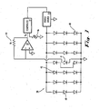
- FIG. 3 is a schematic illustration depicting another embodiment in accordance with the invention.
- circuitry is shown that enables use of at least one semiconductor device 19 of an array 20 as a detector 36 from among the other semiconductor devices 19 of the array.
- all other such devices in the array 20 are used to provide radiant output.
- an array 20 includes a plurality of diodes 40. Except for one of these diodes, all of the plurality of diodes 40 are implemented to emit light.
- the remaining diode 41 is implemented as a detector 36.
- the diode 41 is implemented to detect at least one characteristic, e.g., radiant output or temperature.
- Detector diode 41 is mounted on the same substrate as LEDs 40. It is an integral part of the array 20 (e.g., if the array 20 is a dense array, the diode 41 has dimensions consistent with the other diodes of the array so as to maintain density). Although the diode 41 is an integral part of the array 20, it is contemplated that the diode 41 may be a LED or any other diode appropriate for detection of the characteristic (e.g., a silicon diode).
- the light emitting diodes 40 are powered by a power source 16. More specifically, the power source 16 is implemented as a constant current programmable power supply outputting a current (I). The power source 16 is controlled by a controller 14. Here, the controller 14 is implemented to have a user-set adjustment mechanism 46 (e.g., a variable resistor, which may be set to provide a desired radiant output level) and an input from coupling electronics 22 (e.g., an operational amplifier 42).
- a user-set adjustment mechanism 46 e.g., a variable resistor, which may be set to provide a desired radiant output level
- an input from coupling electronics 22 e.g., an operational amplifier 42.
- the operational amplifier 42 is configured to measure the photocurrent of the detector diode 41. More specifically, the operational amplifier 42 is configured as a trans-impedance (current-to-voltage converter) amplifier. The amplifier's non-inverting input (+) is grounded. The amplifier's inverting input (-) is coupled to the diode 41, as well as to a feedback resistor (Rf). As such, the inverting input is a virtual ground.
- the photocurrent from the diode 41 is driven into the virtual ground. Therefore, diode 41 is operated in a photovoltaic mode, rather than a reverse-biased mode. With this configuration, a substantially high degree of output linearity is maintained.
- Vo is the output voltage of operational amplifier 42
- I is the photocurrent
- Rf is the feedback resistor.
- the feedback resistor here sets gain.
- the output voltage Vo is proportional to the photocurrent from the diode 41, which photocurrent will have some relationship(s) with the radiant output of the array 20 and, therein, some relationship(s) to the radiant output delivered to the work piece 26.
- the controller 14 is implemented so as to enable comparison of Vo to a desired set voltage in order to control the power source 16.
- the power source 16 implemented as a constant current power supply, thereby has its output current adjusted, which adjustment is generally made to maintain a desired radiant output from (or desired temperature for) the emitting array 20.
- the depicted embodiment uses a single, array-centric detector diode in and surrounding by a linear array of emitting diodes
- any number of detector diodes may be used and that a plurality of detector diodes may be used that are not necessarily adjacent to each other and which may not be array centric. Indeed, all detector diodes may be around the periphery of the array.
- the detector diodes may be distributed in and throughout the emitting array in order to measure a desired average photocurrent or average temperature. It is also understood that a plurality of detector diodes may be used, together with a plurality of measurement circuits or a single measurement circuit with a switch multiplexer in order to measure particular areas of the emitting array.
- Figure 4 shows equipment used to evaluate a monitoring technique in accordance with the invention.
- a detector array is a reverse-biased array model no. RX5 (consisting of blue LEDs) made by Phoseon Technology, Beaverton, Oregon, shown on top (SSDs wired in reverse bias).
- the light source is a model no. RX20, also made by Phoseon Technology, Beaverton, Oregon, shown on the bottom and inverted to emit light.
- the photocurrent was measured using an in-line multimeter capable of resolving current with a resolution of 0.1 micro-amps.
- the photocurrent of the light source was read with the multimeter shown in the foreground. By changing the drive current to the light source the amount of light was changed, which was read as a change in the photocurrent.
- the procedure consisted of: setting the current (light output) on the light source, reading the photocurrent from the detector array, turning off the light source, and allowing it to cool down, and repeating the process with a new current.
- Figure 5 is a graph showing the measured results of the evaluation of Fig. 4 .
- the horizontal axis represents the drive current to the light source and the vertical axis represents the resulting photocurrent from the detector array.
- the light source was pulsed on and was not operated at thermal equilibrium.
- the high photocurrent (nearly a milliamp) generally is readily measured, indicating promise for monitoring consistent with this evaluation technique.
- the evaluation indicates several desirable aspects. It requires no additional hardware, e.g., no additional photo detectors or mounting equipment. It enables distribution of light sensor detector diodes (photodiodes) throughout the array, thus providing distributed performance measures over the life of the device. Furthermore, it provides radiant output monitoring integral with the array. As well, it has no moving parts, and the detector diodes generally do not interfere with the radiant output. Also, it provides a means of configuring the RX product to give a specified dose of UV radiation.
- this evaluation method contemplates that the detector diodes are physically wired into the circuit board differently than the emitting LEDs. In that way, the detector diodes can be biased in reverse at a constant voltage. Also, additional circuitry is used to sense the photocurrent and store the information, but such circuitry is anticipated for any such monitoring effort. In addition, if the emitting LEDs are mounted in a reflector cup, as is desirable, the emitting LEDs will be optically shielded from the detector diodes (except for reflections off a window and off the work piece 26), which generally is indicated by reduced photocurrents.
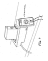
- Figure 6 shows a long-term setup showing the detector array housing with a single LED board (as in Fig. 4 ) and operating with a single power supply.
- One of the columns in the LED array has been electrically removed from the forward-current circuit and is reverse-biased.
- a multimeter is used to sense the voltage across a 100,000 ohm resistor. This voltage has been found to be substantially proportional to the photocurrent (and hence optical flux) generated in the reverse-biased detector diodes by the LEDs.
- Typical voltage drop across the 100,000 ohm resistor has been measured at about 0.75 ohm and, as such, the photocurrent in this test (10.0 volts, 3.9 amps - - driving the fan and LED array in parallel) is determined to be about 7.5 microamps.
- Multi-use devices are understood to be either multimode or multifunction, or both.
- Devices that are multifunction are able to be configured so as to detect from among a plurality of characteristics, such as, for example, radiant output, temperature, magnetic fields, or vibration.
- Multifunction devices preferably are dynamically configurable. Multifunction devices are switched among these detection functions in accordance width the application parameters or other determinative factors.
- Devices that are multimode are capable of, for example, emission, detection and other modes (e.g., off) Multimode devices preferably are dynamically switchable. Multimode devices are switched among modes in accordance with the application parameters or other determinative factors.
- an optical array 100 includes at least one semiconductor device 102 used as a detector diode that can be switched to measure the radiant output of the array and the temperature of the array.
- Detector diode 102 may be of the type discussed above with reference to Fig. 3 for measuring radiant output, but also measures the temperature of array 100.
- detector diode 102 is placed at a selected location within array 100 to measure radiant output and temperature. The selected location is determined by a number of factors such as, for example, the particular process for which array 100 is used as discussed above with reference to Fig. 3 and/or the material of the substrate. For example, substrates of certain materials may have "hot spots" or areas that are more susceptible to heat generated by the LEDs than other areas. In such circumstances, detector diode 102 is located within array 100 at or near the "hot spot" to measure temperature.
- Detector diode 102 measures radiant output as discussed above and utilizes the forward bias potential dependence on temperature to measure the thermal performance of the system. Detector diode 102 is an integral part of array 100 and may be used not only as detector diode but also to produce the radiant intensity of the system. Detector diode 102 is addressed separately by the power supply from the illuminating LEDs. Detector diode 102 is periodically polled by a CPU or controller. The temperature data is retained in a data archival system to monitor the temperature and adjust the power to array 100 accordingly.
- semiconductor devices 102 are powered by a constant current programmable power supply 106 that outputs a current (1).
- Power supply 106 is programmed by a controller 108 that has a user set adjustment and an input from operational amplifier (A1).
- Array 100 includes one or more diodes 102 for measuring radiant output and temperature. Diodes 102 may be LEDs or other appropriate diodes, such as, for example, silicon diodes.
- Diodes 102 used for detection are connected to a circuit 110 for operation in either one of two modes. In a first mode (mode 1), detector diodes 102 measure radiant output from emitting diodes or the LEDs. In a second mode (mode 2), the detector diodes 102 measure temperature. Operational amplifier (A1) is used for both mode 1 and mode 2. Switches S1 and S2 are employed to switch between modes. Although Fig. 7 omits to depict a mechanism controlling the switches, it is understood that, in an example embodiment, controller 108 provides that control. Moreover, it is also understood that controller 108 of Fig. 7 generally functions correlatively to the controller 14 of Fig. 1 (e.g., control of the switches S1 and S2 correlates to control of the coupling electronics 22 in Fig. 1 ).
- operational amplifier (A1) is configured as a trans-impedance (current-to-voltage) amplifier with the photocurrent from the detector diodes 102 driven into a virtual ground to maintain the highest degree of output linearity.
- switch (S2) is closed in order to short out input resistor (Ri) and switch (S1), is opened to prevent voltage (V) from imposing a current into the detecting diodes.
- the non-inverting input is grounded so that detector diodes 102 see virtual ground at the inverting input terminal of operational amplifier (A1).
- the controller compares output voltage (Vo) to a desired set voltage to command programmable power supply 106 to change its output current, e.g., to maintain the desired emitting array output lever.
- a current from voltage (V) is used with resistor (R) to provide a forward bias for detector diodes 102.
- switch (S1) is closed and switch (S2) is open.
- the output voltage (Vo) will be a function of temperature of array 100.
- three diodes 102 in series would result in a change of -5.4 mV/degree C.
- the measured value of temperature may be used by controller 108 to limit the power supply current in order not to exceed a desired temperature level that might be harmful to array 100. Controller 108 may also activate fans or other cooling means (such as seen at 18 in Fig. 1 ) or disable power supply 106 (e.g., upon the loss of cooling means when the temperature exceeds a certain level).
- the controller can apply a pre-determined algorithm to subtract off the error produced by the photocurrent during the temperature measurement function.
- the controller can use other diodes to sense the temperature and determine the photovoltaic current concurrently with the temperature.
- the array may include one or more thermal diodes to measure only the temperature.
- the diodes selected for measuring temperature may be connected to separate circuits from light emitting diodes or light sensing diodes.
- the thermal diodes may be darkened to measure the temperature of the array. Diodes may be darkened a number of ways including coating the diode with an opaque material or covering the diode with a controllably opaque/transparent cover. Furthermore, the diodes may be darkened by turning off power to emitting LEDs in the array and thereupon measuring temperature. Additionally, the embodiment of Fig.
- the array 7 shows a linear array of three detector diodes contained in a linear array of emitting diodes.
- the array may include a plurality of detector diode segments with corresponding measurement circuits or a single measurement circuit with a switch multiplexer to measure particular areas of the LED array.
- each segment/series may be illuminated for a certain percentage of operational time (99%, for example) and used as a detector the rest of the operational time (1 %) to get a mapping of the illumination without affecting the time-averaged uniformity.
Landscapes
- Led Device Packages (AREA)
- Led Devices (AREA)
Claims (8)
- Système photoréactif destiné à irradier une pièce à usiner, comprenant :un réseau (20) de diodes électroluminescentes (19), destiné à irradier la pièce à usiner (26), les diodes électroluminescentes présentant une ou plusieurs caractéristiques associées à l'irradiation de la pièce à usiner (26) ;caractériséen ce qu'au moins une diode électroluminescente (19) dans le réseau (20) est exécutée en tant que détecteur (41) connecté électriquement à un circuit (22) différent de celui des autres diodes électroluminescentes (19), le circuit servant à appliquer une polarisation électrique inversée à la diode électroluminescente de détection (41), la diode électroluminescente de détection (41) étant agencée pour fonctionner dans un mode photovoltaïque et ayant sa sortie couplée à un amplificateur à transimpédance (42) afin de générer un signal proportionnel à un photocourant provenant du détecteur (41), le détecteur (41) étant situé dans une position choisie dans le réseau afin de surveiller de manière sélective une ou plusieurs caractéristiques des diodes électroluminescentes (19) à un emplacement choisi dans le réseau (20) et configuré pour générer un signal correspondant à la caractéristique choisie ;un dispositif de commande (14) étant configuré pour commander une partie ou des parties spécifiques du réseau en réaction au signal provenant de l'au moins un détecteur (41), etle détecteur (41) étant une unique diode de détection au centre du réseau dans et entourée par un réseau linéaire de diodes émettrices (19).
- Système photoréactif selon la revendication 1, dans lequel une parmi l'une ou les plusieurs caractéristiques est la sortie énergétique des dispositifs semi-conducteurs.
- Système photoréactif selon la revendication 1, comprenant en outre au moins une diode électroluminescente conçue et agencée pour mesurer la sortie énergétique du réseau et la chaleur générée par les diodes électroluminescentes.
- Système photoréactif selon les revendications 1 à 3, dans lequel au moins une diode thermique est située dans le réseau pour surveiller la chaleur générée par les diodes électroluminescentes et un dispositif de commande est configuré pour commander les dispositifs électroluminescents en réaction au signal provenant de l'au moins une diode thermique.
- Système photoréactif selon la revendication 1, dans lequel un ensemble de diodes électroluminescentes (19), exécutées pour fonctionner comme détecteurs, est positionné à des positions choisies dans le réseau (20) de diodes électroluminescentes (19) pour surveiller une/des caractéristique(s) choisie(s).
- Procédé de commande d'un système photoréactif, comprenant :la mise à disposition d'un réseau (20) de diodes électroluminescentes (19) destiné à irradier une pièce à usiner (26), les diodes électroluminescentes (19) présentant plusieurs caractéristiques associées à l'irradiation de la pièce à usiner (26),les diodes électroluminescentes (19) présentant plusieurs caractéristiques associées à l'irradiation de la pièce à usiner (26),les diodes électroluminescentes (19) produisant une sortie énergétique afin d'irradier la pièce à usiner (26), de telle sorte que la production de la sortie énergétique génère de la chaleur ; caractérisé en ce que le procédé comprend en outrel'application d'une polarisation électrique inversée sur une diode électroluminescente exécutée comme détecteur (41), la diode électroluminescente de détection (41) étant agencée pour fonctionner dans un mode photovoltaïque et ayant sa sortie couplée à un amplificateur à transimpédance (42) afin de générer un signal proportionnel à un photocourant provenant du détecteur (41), dans lequelladite diode électroluminescente de détection (41) est située dans une position choisie dans le réseau afin de surveiller de manière sélective une ou plusieurs caractéristiques des diodes électroluminescentes à un emplacement choisi dans le réseau (20) et configurée pour générer un signal correspondant à la caractéristique choisie,la mise à disposition d'un dispositif de commande configuré pour commander une partie ou des parties spécifiques du réseau de diodes électroluminescentes (19) en réaction au signal provenant de l'au moins un détecteur (41), etle détecteur (41) étant une unique diode de détection au centre du réseau dans et entourée par un réseau linéaire de diodes émettrices (19).
- Procédé selon la revendication 6, comprenant en outre le fonctionnement de l'au moins un détecteur (41) dans un premier mode afin de surveiller une première des plusieurs caractéristiques des diodes électroluminescentes (19) et le fonctionnement de l'au moins un détecteur (41) dans un second mode afin de surveiller une deuxième des plusieurs caractéristiques des diodes électroluminescentes (19).
- Procédé selon la revendication 7, dans lequel la production de la sortie énergétique génère de la chaleur, dans lequel la sortie énergétique est la première des plusieurs caractéristiques des diodes électroluminescentes (19) et la chaleur est la deuxième des plusieurs caractéristiques des diodes électroluminescentes (19).
Applications Claiming Priority (2)
| Application Number | Priority Date | Filing Date | Title |
|---|---|---|---|
| US55820504P | 2004-03-30 | 2004-03-30 | |
| PCT/US2005/011216 WO2005094390A2 (fr) | 2004-03-30 | 2005-03-30 | Reseau del possedant des detecteurs del fonctionnant sur la base sur ce reseau |
Publications (3)
| Publication Number | Publication Date |
|---|---|
| EP1743384A2 EP1743384A2 (fr) | 2007-01-17 |
| EP1743384A4 EP1743384A4 (fr) | 2009-09-09 |
| EP1743384B1 true EP1743384B1 (fr) | 2015-08-05 |
Family
ID=35064345
Family Applications (1)
| Application Number | Title | Priority Date | Filing Date |
|---|---|---|---|
| EP05742823.7A Expired - Lifetime EP1743384B1 (fr) | 2004-03-30 | 2005-03-30 | Reseau del possedant des detecteurs del fonctionnant sur la base sur ce reseau |
Country Status (3)
| Country | Link |
|---|---|
| US (2) | US7816638B2 (fr) |
| EP (1) | EP1743384B1 (fr) |
| WO (1) | WO2005094390A2 (fr) |
Families Citing this family (46)
| Publication number | Priority date | Publication date | Assignee | Title |
|---|---|---|---|---|
| ATE535009T1 (de) | 2002-05-08 | 2011-12-15 | Phoseon Technology Inc | Hocheffiziente halbleiter-lichtquelle sowie verfahren zu deren verwendung und herstellung |
| WO2005043954A2 (fr) | 2003-10-31 | 2005-05-12 | Phoseon Technology, Inc. | Cablage en serie de sources lumineuses hautement fiables |
| US7819550B2 (en) | 2003-10-31 | 2010-10-26 | Phoseon Technology, Inc. | Collection optics for led array with offset hemispherical or faceted surfaces |
| US10154551B2 (en) | 2004-02-25 | 2018-12-11 | Lynk Labs, Inc. | AC light emitting diode and AC LED drive methods and apparatus |
| US10091842B2 (en) | 2004-02-25 | 2018-10-02 | Lynk Labs, Inc. | AC light emitting diode and AC LED drive methods and apparatus |
| US10575376B2 (en) | 2004-02-25 | 2020-02-25 | Lynk Labs, Inc. | AC light emitting diode and AC LED drive methods and apparatus |
| US10499466B1 (en) | 2004-02-25 | 2019-12-03 | Lynk Labs, Inc. | AC light emitting diode and AC LED drive methods and apparatus |
| US10499465B2 (en) | 2004-02-25 | 2019-12-03 | Lynk Labs, Inc. | High frequency multi-voltage and multi-brightness LED lighting devices and systems and methods of using same |
| WO2005091392A1 (fr) | 2004-03-18 | 2005-09-29 | Phoseon Technology, Inc. | Micro-reflecteurs montes sur un substrat et destines a un reseau del haute densite |
| EP1754259B1 (fr) | 2004-03-18 | 2019-07-17 | Phoseon Technology, Inc. | Refroidissement direct et indirect de del |
| US7816638B2 (en) | 2004-03-30 | 2010-10-19 | Phoseon Technology, Inc. | LED array having array-based LED detectors |
| ES2363435T3 (es) * | 2004-04-12 | 2011-08-04 | Phoseon Technology, Inc. | Matriz led de alta densidad. |
| WO2005100961A2 (fr) | 2004-04-19 | 2005-10-27 | Phoseon Technology, Inc. | Structures semi-conductrices d'imagerie utilisant un eclairage a semi-conducteurs |
| EP1598200A3 (fr) * | 2004-05-21 | 2009-05-06 | Seiko Epson Corporation | Tête en ligne et dispositif de formation d'images comprenent cette tête |
| US9281001B2 (en) | 2004-11-08 | 2016-03-08 | Phoseon Technology, Inc. | Methods and systems relating to light sources for use in industrial processes |
| US7642527B2 (en) | 2005-12-30 | 2010-01-05 | Phoseon Technology, Inc. | Multi-attribute light effects for use in curing and other applications involving photoreactions and processing |
| JP4981915B2 (ja) | 2006-10-16 | 2012-07-25 | オートリブ ディベロップメント エービー | 可撓性固定連結具を備えるエアバッグ |
| WO2009001237A1 (fr) * | 2007-06-25 | 2008-12-31 | Koninklijke Philips Electronics N.V. | Autotest de photodiode |
| US9781803B2 (en) * | 2008-11-30 | 2017-10-03 | Cree, Inc. | LED thermal management system and method |
| US8653737B2 (en) * | 2009-04-14 | 2014-02-18 | Phoseon Technology, Inc. | Controller for semiconductor lighting device |
| EP2428098B1 (fr) * | 2009-04-29 | 2018-04-11 | Tridonic GmbH & Co KG | Dispositif pour faire fonctionner des del |
| WO2011016908A1 (fr) * | 2009-08-03 | 2011-02-10 | Illinois Tool Works Inc. | Capteur dinterruption optique doté de diodes électroluminescentes opposées |
| US8466628B2 (en) * | 2009-10-07 | 2013-06-18 | Lutron Electronics Co., Inc. | Closed-loop load control circuit having a wide output range |
| US8330377B2 (en) * | 2009-12-10 | 2012-12-11 | Phoseon Technology, Inc. | Monitoring voltage to track temperature in solid state light modules |
| US12279345B2 (en) | 2009-12-28 | 2025-04-15 | Lynk Labs, Inc. | Light emitting diode and LED drive apparatus |
| DE112010005248B4 (de) | 2010-02-10 | 2017-06-01 | Excelitas Canada Inc. | Modulare led-array-lichtquellen von hoher dichte |
| US9735303B2 (en) * | 2010-03-25 | 2017-08-15 | Nri R&D Patent Licensing, Llc | Color imaging using color OLED or LED array as color light-field imaging sensor |
| TWI397708B (zh) * | 2010-04-06 | 2013-06-01 | Ind Tech Res Inst | 太陽能電池之量測系統和太陽光模擬器 |
| US8680787B2 (en) | 2011-03-15 | 2014-03-25 | Lutron Electronics Co., Inc. | Load control device for a light-emitting diode light source |
| US20140239809A1 (en) * | 2011-08-18 | 2014-08-28 | Lynk Labs, Inc. | Devices and systems having ac led circuits and methods of driving the same |
| US9057757B2 (en) * | 2011-08-21 | 2015-06-16 | Bruker Nano, Inc. | Testing of electroluminescent semiconductor wafers |
| US8730383B2 (en) | 2011-11-30 | 2014-05-20 | Cognex Corporation | System and method for controlling illumination in a vision system |
| WO2013082609A1 (fr) | 2011-12-02 | 2013-06-06 | Lynk Labs, Inc. | Dispositifs d'éclairage par del à faible distorsion harmonique totale (dht) à commande de température de couleur et leurs systèmes et procédés de pilotage |
| US8746923B2 (en) | 2011-12-05 | 2014-06-10 | Cooledge Lighting Inc. | Control of luminous intensity distribution from an array of point light sources |
| US10091852B2 (en) * | 2014-10-24 | 2018-10-02 | Phoseon Technology, Inc. | Lighting system and methods for reducing noise at light sensing device |
| DE102014018934A1 (de) * | 2014-12-22 | 2016-06-23 | Airbus Defence and Space GmbH | Vorrichtung zum Aufheizen eines Verbundwerkstoffs mit temperaturabhängigen Verarbeitungseigenschaften und damit zusammenhängende Verfahren |
| US10557279B1 (en) * | 2016-04-08 | 2020-02-11 | Boss Ltg, Inc. | Rotating light tower assembly |
| DE102017105131A1 (de) * | 2017-03-10 | 2018-09-13 | Osram Opto Semiconductors Gmbh | Verfahren zum Betreiben eines optoelektronischen Bauelements und optoelektronisches Bauelement |
| IT201800003972A1 (it) * | 2018-03-26 | 2019-09-26 | Enrico Vannacci | Dispositivo opto-elettronico comprendente un led in polarizzazione diretta, utilizzato come rilevatore di radiazione, e suoi impieghi |
| DE112019001927T5 (de) | 2018-05-31 | 2021-03-11 | Phoseon Technology, Inc. | Verfahren und system zum kalibrieren von uv-lichtquellen |
| US10895649B2 (en) * | 2018-09-20 | 2021-01-19 | Phoseon Technology, Inc. | Methods and system for thermo-optic power monitoring |
| JP2021004809A (ja) * | 2019-06-26 | 2021-01-14 | マークテック株式会社 | 紫外線led照射装置 |
| DE102019135234A1 (de) * | 2019-12-19 | 2021-06-24 | HELLA GmbH & Co. KGaA | Lichtquellenmodul |
| US11215934B2 (en) * | 2020-01-21 | 2022-01-04 | Applied Materials, Inc. | In-situ light detection methods and apparatus for ultraviolet semiconductor substrate processing |
| US11628234B2 (en) | 2020-06-01 | 2023-04-18 | Know Labs, Inc. | White light LED light bulbs for ambient lighting and pathogen inactivation |
| US12540867B2 (en) * | 2022-04-19 | 2026-02-03 | Apple Inc. | Temperature sensing using optical sensors |
Citations (1)
| Publication number | Priority date | Publication date | Assignee | Title |
|---|---|---|---|---|
| US6683421B1 (en) * | 2001-01-25 | 2004-01-27 | Exfo Photonic Solutions Inc. | Addressable semiconductor array light source for localized radiation delivery |
Family Cites Families (136)
| Publication number | Priority date | Publication date | Assignee | Title |
|---|---|---|---|---|
| GB1218852A (en) | 1968-04-02 | 1971-01-13 | English Electric Co Ltd | High voltage thyristor equipment |
| US4435732A (en) | 1973-06-04 | 1984-03-06 | Hyatt Gilbert P | Electro-optical illumination control system |
| US3936686A (en) | 1973-05-07 | 1976-02-03 | Moore Donald W | Reflector lamp cooling and containing assemblies |
| US4011575A (en) | 1974-07-26 | 1977-03-08 | Litton Systems, Inc. | Light emitting diode array having a plurality of conductive paths for each light emitting diode |
| JPS57180005A (en) | 1981-04-30 | 1982-11-05 | Hitachi Ltd | Silicon carbide electric insulator with low dielectric constant |
| NL8200517A (nl) * | 1982-02-11 | 1983-09-01 | Tno | Instelschakeling voor licht-emitterende diode met temperatuurcompensatie. |
| US4595289A (en) | 1984-01-25 | 1986-06-17 | At&T Bell Laboratories | Inspection system utilizing dark-field illumination |
| US4530040A (en) | 1984-03-08 | 1985-07-16 | Rayovac Corporation | Optical focusing system |
| US4680644A (en) | 1984-07-23 | 1987-07-14 | Canon Kabushiki Kaisha | Method and apparatus for reading an image |
| WO1986002045A1 (fr) | 1984-09-27 | 1986-04-10 | Sanyo Electric Co., Ltd. | Tete imprimante optique pour appareil a impression optique |
| US4684801A (en) | 1986-02-28 | 1987-08-04 | Carroll Touch Inc. | Signal preconditioning for touch entry device |
| KR880014692A (ko) | 1987-05-30 | 1988-12-24 | 강진구 | 반사경이 부착된 반도체 발광장치 |
| GB2224374A (en) * | 1988-08-24 | 1990-05-02 | Plessey Co Plc | Temperature control of light-emitting devices |
| ATE149743T1 (de) | 1990-04-27 | 1997-03-15 | Omron Tateisi Electronics Co | Lichtemittierende halbleitervorrichtung mit fresnel-linse |
| US5150623A (en) | 1990-07-17 | 1992-09-29 | The Boeing Company | Inspection device for flush head bolts and rivets |
| JPH087096B2 (ja) * | 1990-11-30 | 1996-01-29 | 防衛庁技術研究本部長 | 赤外検知装置 |
| US5195102A (en) | 1991-09-13 | 1993-03-16 | Litton Systems Inc. | Temperature controlled laser diode package |
| JP3025109B2 (ja) | 1992-03-11 | 2000-03-27 | シャープ株式会社 | 光源および光源装置 |
| DE4225829A1 (de) * | 1992-08-05 | 1994-02-10 | Hoechst Ag | Vorbehandlungseinrichtung für bildmäßig zu belichtende Druckformen |
| US5397867A (en) | 1992-09-04 | 1995-03-14 | Lucas Industries, Inc. | Light distribution for illuminated keyboard switches and displays |
| JPH06301304A (ja) | 1993-02-19 | 1994-10-28 | Minolta Camera Co Ltd | 定着装置 |
| US5311353A (en) * | 1993-03-05 | 1994-05-10 | Analog Modules | Wide dynamic range optical receivers |
| US6118383A (en) * | 1993-05-07 | 2000-09-12 | Hegyi; Dennis J. | Multi-function light sensor for vehicle |
| ES2106520T3 (es) | 1993-05-19 | 1997-11-01 | Fraunhofer Ges Forschung | Procedimiento que permite el trabajo de materiales por radiacion emitida por diodos. |
| FR2707223B1 (fr) | 1993-07-07 | 1995-09-29 | Valeo Vision | Feu de signalisation perfectionné à diodes électroluminescentes. |
| US5424544A (en) | 1994-04-29 | 1995-06-13 | Texas Instruments Incorporated | Inter-pixel thermal isolation for hybrid thermal detectors |
| US5632551A (en) | 1994-07-18 | 1997-05-27 | Grote Industries, Inc. | LED vehicle lamp assembly |
| US5698866A (en) | 1994-09-19 | 1997-12-16 | Pdt Systems, Inc. | Uniform illuminator for phototherapy |
| US5555038A (en) | 1994-10-28 | 1996-09-10 | Bausch & Lomb Incorporated | Unitary lens for eyewear |
| US5660461A (en) | 1994-12-08 | 1997-08-26 | Quantum Devices, Inc. | Arrays of optoelectronic devices and method of making same |
| US5522225A (en) | 1994-12-19 | 1996-06-04 | Xerox Corporation | Thermoelectric cooler and temperature sensor subassembly with improved temperature control |
| US5554849A (en) * | 1995-01-17 | 1996-09-10 | Flir Systems, Inc. | Micro-bolometric infrared staring array |
| US5670780A (en) | 1995-04-14 | 1997-09-23 | Lewis; W. Stan | Device providing real-time orientation and direction of an object |
| US5623510A (en) | 1995-05-08 | 1997-04-22 | The United States Of America As Represented By The United States Department Of Energy | Tunable, diode side-pumped Er: YAG laser |
| SG42307A1 (en) | 1996-01-09 | 1997-08-15 | Peng Seng Toh | Measurement and inspection of leads on integrated circuit packages |
| US5719589A (en) | 1996-01-11 | 1998-02-17 | Motorola, Inc. | Organic light emitting diode array drive apparatus |
| US5806965A (en) | 1996-01-30 | 1998-09-15 | R&M Deese, Inc. | LED beacon light |
| IL118872A (en) | 1996-07-16 | 2000-06-01 | Orbot Instr Ltd | Optical inspection method and apparatus |
| US6058012A (en) | 1996-08-26 | 2000-05-02 | Compaq Computer Corporation | Apparatus, method and system for thermal management of an electronic system having semiconductor devices |
| US5857767A (en) | 1996-09-23 | 1999-01-12 | Relume Corporation | Thermal management system for L.E.D. arrays |
| US5715270A (en) | 1996-09-27 | 1998-02-03 | Mcdonnell Douglas Corporation | High efficiency, high power direct diode laser systems and methods therefor |
| US5910706A (en) | 1996-12-18 | 1999-06-08 | Ultra Silicon Technology (Uk) Limited | Laterally transmitting thin film electroluminescent device |
| TW402856B (en) | 1996-12-26 | 2000-08-21 | Palite Corp | LED illuminator |
| US5783909A (en) * | 1997-01-10 | 1998-07-21 | Relume Corporation | Maintaining LED luminous intensity |
| US5877899A (en) | 1997-05-13 | 1999-03-02 | Northeast Robotics Llc | Imaging system and method for imaging indicia on wafer |
| US6319425B1 (en) | 1997-07-07 | 2001-11-20 | Asahi Rubber Inc. | Transparent coating member for light-emitting diodes and a fluorescent color light source |
| US6459919B1 (en) | 1997-08-26 | 2002-10-01 | Color Kinetics, Incorporated | Precision illumination methods and systems |
| US6211626B1 (en) | 1997-08-26 | 2001-04-03 | Color Kinetics, Incorporated | Illumination components |
| US6577332B2 (en) | 1997-09-12 | 2003-06-10 | Ricoh Company, Ltd. | Optical apparatus and method of manufacturing optical apparatus |
| US6163036A (en) * | 1997-09-15 | 2000-12-19 | Oki Data Corporation | Light emitting element module with a parallelogram-shaped chip and a staggered chip array |
| US6200134B1 (en) | 1998-01-20 | 2001-03-13 | Kerr Corporation | Apparatus and method for curing materials with radiation |
| EP0935145A1 (fr) | 1998-02-04 | 1999-08-11 | IMS Industrial Micro System AG | Dispositif optique de signalisation ou d'affichage |
| US6239702B1 (en) * | 1998-03-10 | 2001-05-29 | Raytheon Company | Electromagnetic energy detection |
| US6088185A (en) * | 1998-06-05 | 2000-07-11 | Seagate Technology, Inc. | Rotational vibration detection using a velocity sense coil |
| US6536923B1 (en) | 1998-07-01 | 2003-03-25 | Sidler Gmbh & Co. | Optical attachment for a light-emitting diode and brake light for a motor vehicle |
| JP3195294B2 (ja) | 1998-08-27 | 2001-08-06 | スタンレー電気株式会社 | 車両用灯具 |
| US20040201988A1 (en) | 1999-02-12 | 2004-10-14 | Fiber Optic Designs, Inc. | LED light string and arrays with improved harmonics and optimized power utilization |
| US6291839B1 (en) | 1998-09-11 | 2001-09-18 | Lulileds Lighting, U.S. Llc | Light emitting device having a finely-patterned reflective contact |
| US6077073A (en) | 1998-09-15 | 2000-06-20 | Jacob; Gregory S. | Light emitting diode-array light apparatus |
| US6534791B1 (en) | 1998-11-27 | 2003-03-18 | Lumileds Lighting U.S., Llc | Epitaxial aluminium-gallium nitride semiconductor substrate |
| US6359274B1 (en) * | 1999-01-25 | 2002-03-19 | Gentex Corporation | Photodiode light sensor |
| US6320206B1 (en) | 1999-02-05 | 2001-11-20 | Lumileds Lighting, U.S., Llc | Light emitting devices having wafer bonded aluminum gallium indium nitride structures and mirror stacks |
| US20010042866A1 (en) | 1999-02-05 | 2001-11-22 | Carrie Carter Coman | Inxalygazn optical emitters fabricated via substrate removal |
| US6155699A (en) | 1999-03-15 | 2000-12-05 | Agilent Technologies, Inc. | Efficient phosphor-conversion led structure |
| WO2000059671A1 (fr) | 1999-04-07 | 2000-10-12 | Mv Research Limited | Inspection de materiau |
| US6097302A (en) * | 1999-06-23 | 2000-08-01 | Union Switch & Signal, Inc. | System and method for monitoring a plural segment light-emitting display |
| DE19931689A1 (de) | 1999-07-08 | 2001-01-11 | Patent Treuhand Ges Fuer Elektrische Gluehlampen Mbh | Optoelektronische Bauteilgruppe |
| US6366017B1 (en) | 1999-07-14 | 2002-04-02 | Agilent Technologies, Inc/ | Organic light emitting diodes with distributed bragg reflector |
| US6160354A (en) | 1999-07-22 | 2000-12-12 | 3Com Corporation | LED matrix current control system |
| TW457732B (en) | 1999-08-27 | 2001-10-01 | Lumileds Lighting Bv | Luminaire, optical element and method of illuminating an object |
| JP4131891B2 (ja) | 1999-09-03 | 2008-08-13 | ローム株式会社 | レンズアレイ、およびレンズアレイの製造方法 |
| US6788895B2 (en) * | 1999-12-10 | 2004-09-07 | Altera Corporation | Security mapping and auto reconfiguration |
| US6455930B1 (en) | 1999-12-13 | 2002-09-24 | Lamina Ceramics, Inc. | Integrated heat sinking packages using low temperature co-fired ceramic metal circuit board technology |
| US6362578B1 (en) | 1999-12-23 | 2002-03-26 | Stmicroelectronics, Inc. | LED driver circuit and method |
| US6611110B1 (en) | 2001-01-16 | 2003-08-26 | Design Rite, Llc | Photopolymerization apparatus |
| US6318886B1 (en) | 2000-02-11 | 2001-11-20 | Whelen Engineering Company | High flux led assembly |
| US7320593B2 (en) | 2000-03-08 | 2008-01-22 | Tir Systems Ltd. | Light emitting diode light source for curing dental composites |
| DE10013207B4 (de) | 2000-03-17 | 2014-03-13 | Tridonic Gmbh & Co Kg | Ansteuerung von Leuchtdioden (LED's) |
| US6419384B1 (en) | 2000-03-24 | 2002-07-16 | Buztronics Inc | Drinking vessel with indicator activated by inertial switch |
| EP1158761A1 (fr) | 2000-05-26 | 2001-11-28 | GRETAG IMAGING Trading AG | Dispositif photographique pour l'acquisition d'images par des circuits à diodes electroluminescentes |
| WO2002001649A1 (fr) | 2000-06-29 | 2002-01-03 | Koninklijke Philips Electronics N.V. | Element optoelectrique |
| JP4142234B2 (ja) | 2000-07-04 | 2008-09-03 | 株式会社エンプラス | 面光源装置及び液晶表示装置 |
| CN1259732C (zh) | 2000-09-29 | 2006-06-14 | 欧姆龙株式会社 | 光学器件及其应用 |
| KR100599214B1 (ko) | 2000-09-29 | 2006-07-12 | 마츠시다 덴코 가부시키가이샤 | 보호기능을 구비한 반도체 장치 |
| US7714301B2 (en) | 2000-10-27 | 2010-05-11 | Molecular Devices, Inc. | Instrument excitation source and calibration method |
| US6525335B1 (en) | 2000-11-06 | 2003-02-25 | Lumileds Lighting, U.S., Llc | Light emitting semiconductor devices including wafer bonded heterostructures |
| GB2369428B (en) * | 2000-11-22 | 2004-11-10 | Imperial College | Detection system |
| US7075112B2 (en) | 2001-01-31 | 2006-07-11 | Gentex Corporation | High power radiation emitter device and heat dissipating package for electronic components |
| US6547249B2 (en) | 2001-03-29 | 2003-04-15 | Lumileds Lighting U.S., Llc | Monolithic series/parallel led arrays formed on highly resistive substrates |
| US7117019B2 (en) * | 2001-03-30 | 2006-10-03 | Motorola, Inc. | Display and keypad backlight management for portable electronic devices |
| US6755647B2 (en) | 2001-04-26 | 2004-06-29 | New Photonics, Llc | Photocuring device with axial array of light emitting diodes and method of curing |
| US6607286B2 (en) | 2001-05-04 | 2003-08-19 | Lumileds Lighting, U.S., Llc | Lens and lens cap with sawtooth portion for light emitting diode |
| US6630689B2 (en) | 2001-05-09 | 2003-10-07 | Lumileds Lighting, U.S. Llc | Semiconductor LED flip-chip with high reflectivity dielectric coating on the mesa |
| US6617795B2 (en) * | 2001-07-26 | 2003-09-09 | Koninklijke Philips Electronics N.V. | Multichip LED package with in-package quantitative and spectral sensing capability and digital signal output |
| US6785001B2 (en) | 2001-08-21 | 2004-08-31 | Silicon Light Machines, Inc. | Method and apparatus for measuring wavelength jitter of light signal |
| JP4067802B2 (ja) | 2001-09-18 | 2008-03-26 | 松下電器産業株式会社 | 照明装置 |
| US6561808B2 (en) | 2001-09-27 | 2003-05-13 | Ceramoptec Industries, Inc. | Method and tools for oral hygiene |
| US6498355B1 (en) | 2001-10-09 | 2002-12-24 | Lumileds Lighting, U.S., Llc | High flux LED array |
| US6561640B1 (en) | 2001-10-31 | 2003-05-13 | Xerox Corporation | Systems and methods of printing with ultraviolet photosensitive resin-containing materials using light emitting devices |
| US7348946B2 (en) * | 2001-12-31 | 2008-03-25 | Intel Corporation | Energy sensing light emitting diode display |
| US6720859B2 (en) | 2002-01-10 | 2004-04-13 | Lamina Ceramics, Inc. | Temperature compensating device with embedded columnar thermistors |
| US6759940B2 (en) | 2002-01-10 | 2004-07-06 | Lamina Ceramics, Inc. | Temperature compensating device with integral sheet thermistors |
| DE10239449B4 (de) * | 2002-02-06 | 2013-10-24 | Ulrich Kuipers | Verfahren und Vorrichtung zur Realisierung von LED-Leuchten mit Farb- und Helligkeitseinstellung und dem dazugehörigen Bedienelement |
| JP3991730B2 (ja) | 2002-03-13 | 2007-10-17 | チッソ株式会社 | 重合性化合物およびその重合体 |
| US6796698B2 (en) | 2002-04-01 | 2004-09-28 | Gelcore, Llc | Light emitting diode-based signal light |
| ATE535009T1 (de) | 2002-05-08 | 2011-12-15 | Phoseon Technology Inc | Hocheffiziente halbleiter-lichtquelle sowie verfahren zu deren verwendung und herstellung |
| DE10223201C1 (de) * | 2002-05-24 | 2003-05-28 | Fraunhofer Ges Forschung | Optikerfassungsvorrichtung |
| US6573536B1 (en) | 2002-05-29 | 2003-06-03 | Optolum, Inc. | Light emitting diode light source |
| US6960402B2 (en) * | 2002-06-28 | 2005-11-01 | Advanced Energy Technology Inc. | Perforated cylindrical fuel cells |
| US7279069B2 (en) | 2002-07-18 | 2007-10-09 | Origin Electric Company Limited | Adhesive curing method, curing apparatus, and optical disc lamination apparatus using the curing apparatus |
| US20040134603A1 (en) | 2002-07-18 | 2004-07-15 | Hideo Kobayashi | Method and apparatus for curing adhesive between substrates, and disc substrate bonding apparatus |
| EP2298229A1 (fr) | 2002-07-25 | 2011-03-23 | Jonathan S. Dahm | Procédé et appareil permettant d'utiliser des diodes électroluminescentes à des fins de cuisson |
| US6798152B2 (en) | 2002-08-21 | 2004-09-28 | Freescale Semiconductor, Inc. | Closed loop current control circuit and method thereof |
| AU2003298561A1 (en) | 2002-08-23 | 2004-05-13 | Jonathan S. Dahm | Method and apparatus for using light emitting diodes |
| US7084935B2 (en) | 2002-08-28 | 2006-08-01 | Adaptive Micro Systems, Llc | Display device with molded light guide |
| US7170606B2 (en) * | 2002-09-20 | 2007-01-30 | Mitsubishi Electric Research Laboratories, Inc. | Multi-way LED-based surface reflectance sensor and spectrophotometer |
| US6822991B2 (en) | 2002-09-30 | 2004-11-23 | Lumileds Lighting U.S., Llc | Light emitting devices including tunnel junctions |
| US6880954B2 (en) | 2002-11-08 | 2005-04-19 | Smd Software, Inc. | High intensity photocuring system |
| US6708501B1 (en) | 2002-12-06 | 2004-03-23 | Nanocoolers, Inc. | Cooling of electronics by electrically conducting fluids |
| TW571449B (en) | 2002-12-23 | 2004-01-11 | Epistar Corp | Light-emitting device having micro-reflective structure |
| US7175712B2 (en) | 2003-01-09 | 2007-02-13 | Con-Trol-Cure, Inc. | Light emitting apparatus and method for curing inks, coatings and adhesives |
| US7465909B2 (en) | 2003-01-09 | 2008-12-16 | Con-Trol-Cure, Inc. | UV LED control loop and controller for causing emitting UV light at a much greater intensity for UV curing |
| US7211299B2 (en) | 2003-01-09 | 2007-05-01 | Con-Trol-Cure, Inc. | UV curing method and apparatus |
| GB0304761D0 (en) | 2003-03-01 | 2003-04-02 | Integration Technology Ltd | Ultraviolet curing |
| US20040206970A1 (en) | 2003-04-16 | 2004-10-21 | Martin Paul S. | Alternating current light emitting device |
| US7002677B2 (en) | 2003-07-23 | 2006-02-21 | Kla-Tencor Technologies Corporation | Darkfield inspection system having a programmable light selection array |
| US7042341B2 (en) * | 2003-08-12 | 2006-05-09 | Overhead Door Corporation | Device including light emitting diode as light sensor and light source |
| WO2005043598A2 (fr) | 2003-10-31 | 2005-05-12 | Phoseon Technology, Inc. | Utilisation de gels d'enrobage pour la fabrication de reseaux micro-optiques |
| WO2005043954A2 (fr) | 2003-10-31 | 2005-05-12 | Phoseon Technology, Inc. | Cablage en serie de sources lumineuses hautement fiables |
| US7819550B2 (en) | 2003-10-31 | 2010-10-26 | Phoseon Technology, Inc. | Collection optics for led array with offset hemispherical or faceted surfaces |
| WO2005091392A1 (fr) | 2004-03-18 | 2005-09-29 | Phoseon Technology, Inc. | Micro-reflecteurs montes sur un substrat et destines a un reseau del haute densite |
| EP1754259B1 (fr) | 2004-03-18 | 2019-07-17 | Phoseon Technology, Inc. | Refroidissement direct et indirect de del |
| US7816638B2 (en) | 2004-03-30 | 2010-10-19 | Phoseon Technology, Inc. | LED array having array-based LED detectors |
| ES2363435T3 (es) | 2004-04-12 | 2011-08-04 | Phoseon Technology, Inc. | Matriz led de alta densidad. |
| WO2005100961A2 (fr) | 2004-04-19 | 2005-10-27 | Phoseon Technology, Inc. | Structures semi-conductrices d'imagerie utilisant un eclairage a semi-conducteurs |
| US9281001B2 (en) | 2004-11-08 | 2016-03-08 | Phoseon Technology, Inc. | Methods and systems relating to light sources for use in industrial processes |
-
2005
- 2005-03-30 US US11/095,210 patent/US7816638B2/en not_active Expired - Lifetime
- 2005-03-30 EP EP05742823.7A patent/EP1743384B1/fr not_active Expired - Lifetime
- 2005-03-30 WO PCT/US2005/011216 patent/WO2005094390A2/fr not_active Ceased
-
2010
- 2010-09-27 US US12/891,649 patent/US8039785B2/en not_active Expired - Fee Related
Patent Citations (1)
| Publication number | Priority date | Publication date | Assignee | Title |
|---|---|---|---|---|
| US6683421B1 (en) * | 2001-01-25 | 2004-01-27 | Exfo Photonic Solutions Inc. | Addressable semiconductor array light source for localized radiation delivery |
Also Published As
| Publication number | Publication date |
|---|---|
| US20110012514A1 (en) | 2011-01-20 |
| WO2005094390A3 (fr) | 2006-11-30 |
| EP1743384A4 (fr) | 2009-09-09 |
| US7816638B2 (en) | 2010-10-19 |
| US20050230600A1 (en) | 2005-10-20 |
| EP1743384A2 (fr) | 2007-01-17 |
| WO2005094390A2 (fr) | 2005-10-13 |
| US8039785B2 (en) | 2011-10-18 |
Similar Documents
| Publication | Publication Date | Title |
|---|---|---|
| EP1743384B1 (fr) | Reseau del possedant des detecteurs del fonctionnant sur la base sur ce reseau | |
| US9024535B2 (en) | Stabilized light source having luminance feedback control | |
| US8810271B2 (en) | Method and apparatus for testing photovoltaic devices | |
| JP5550690B2 (ja) | 較正機能付きled光モジュール | |
| EP1941785B1 (fr) | Dispositif d'eclairage couleur | |
| US5283425A (en) | Light emitting element array substrate with reflecting means | |
| CN1240960C (zh) | 具有用于光反馈的光学传感器结构的发光二极管光源 | |
| US20070105212A1 (en) | Temperature control for light-emitting diode stabilization | |
| WO2007078964A1 (fr) | Capteur de couleur | |
| CN105546494B (zh) | 用于减少光传感装置的噪音的照明系统和方法 | |
| KR101987506B1 (ko) | 측정 장치 및 측정 방법 | |
| JP5387979B2 (ja) | リニアリティ検査装置及びリニアリティ検査方法 | |
| KR20080045130A (ko) | 컬러 포인트 제어 시스템 | |
| US11262460B2 (en) | Methods and system for thermo-optic power monitoring | |
| EP1240484B1 (fr) | Procede et dispositif destines a mesurer l'intensite moyennee dans l'espace d'un faisceau lumineux, et procede et dispositif de regulation de source lumineuse | |
| KR20090079594A (ko) | 발광 다이오드의 특성을 검사하는 장치 | |
| JPWO2020151932A5 (fr) |
Legal Events
| Date | Code | Title | Description |
|---|---|---|---|
| PUAI | Public reference made under article 153(3) epc to a published international application that has entered the european phase |
Free format text: ORIGINAL CODE: 0009012 |
|
| 17P | Request for examination filed |
Effective date: 20060623 |
|
| AK | Designated contracting states |
Kind code of ref document: A2 Designated state(s): AT BE BG CH CY CZ DE DK EE ES FI FR GB GR HU IE IS IT LI LT LU MC NL PL PT RO SE SI SK TR |
|
| AX | Request for extension of the european patent |
Extension state: AL BA HR LV MK YU |
|
| RIN1 | Information on inventor provided before grant (corrected) |
Inventor name: ANDERSON, DUWAYNE, R. Inventor name: CULTER, ROBERT, G. Inventor name: OLSON, STEVEN, J. Inventor name: OWEN, MARK, D. |
|
| DAX | Request for extension of the european patent (deleted) | ||
| A4 | Supplementary search report drawn up and despatched |
Effective date: 20090812 |
|
| RIC1 | Information provided on ipc code assigned before grant |
Ipc: H01L 31/12 20060101ALI20090806BHEP Ipc: H01L 31/153 20060101ALI20090806BHEP Ipc: H05B 33/08 20060101AFI20090806BHEP |
|
| 17Q | First examination report despatched |
Effective date: 20100129 |
|
| RAP1 | Party data changed (applicant data changed or rights of an application transferred) |
Owner name: PHOSEON TECHNOLOGY, INC. |
|
| GRAP | Despatch of communication of intention to grant a patent |
Free format text: ORIGINAL CODE: EPIDOSNIGR1 |
|
| INTG | Intention to grant announced |
Effective date: 20150401 |
|
| GRAS | Grant fee paid |
Free format text: ORIGINAL CODE: EPIDOSNIGR3 |
|
| GRAA | (expected) grant |
Free format text: ORIGINAL CODE: 0009210 |
|
| AK | Designated contracting states |
Kind code of ref document: B1 Designated state(s): AT BE BG CH CY CZ DE DK EE ES FI FR GB GR HU IE IS IT LI LT LU MC NL PL PT RO SE SI SK TR |
|
| REG | Reference to a national code |
Ref country code: GB Ref legal event code: FG4D |
|
| REG | Reference to a national code |
Ref country code: CH Ref legal event code: EP |
|
| REG | Reference to a national code |
Ref country code: AT Ref legal event code: REF Ref document number: 741282 Country of ref document: AT Kind code of ref document: T Effective date: 20150815 |
|
| REG | Reference to a national code |
Ref country code: IE Ref legal event code: FG4D |
|
| REG | Reference to a national code |
Ref country code: DE Ref legal event code: R096 Ref document number: 602005047153 Country of ref document: DE |
|
| REG | Reference to a national code |
Ref country code: AT Ref legal event code: MK05 Ref document number: 741282 Country of ref document: AT Kind code of ref document: T Effective date: 20150805 |
|
| REG | Reference to a national code |
Ref country code: LT Ref legal event code: MG4D |
|
| REG | Reference to a national code |
Ref country code: NL Ref legal event code: MP Effective date: 20150805 |
|
| PG25 | Lapsed in a contracting state [announced via postgrant information from national office to epo] |
Ref country code: LT Free format text: LAPSE BECAUSE OF FAILURE TO SUBMIT A TRANSLATION OF THE DESCRIPTION OR TO PAY THE FEE WITHIN THE PRESCRIBED TIME-LIMIT Effective date: 20150805 Ref country code: FI Free format text: LAPSE BECAUSE OF FAILURE TO SUBMIT A TRANSLATION OF THE DESCRIPTION OR TO PAY THE FEE WITHIN THE PRESCRIBED TIME-LIMIT Effective date: 20150805 Ref country code: GR Free format text: LAPSE BECAUSE OF FAILURE TO SUBMIT A TRANSLATION OF THE DESCRIPTION OR TO PAY THE FEE WITHIN THE PRESCRIBED TIME-LIMIT Effective date: 20151106 |
|
| PG25 | Lapsed in a contracting state [announced via postgrant information from national office to epo] |
Ref country code: ES Free format text: LAPSE BECAUSE OF FAILURE TO SUBMIT A TRANSLATION OF THE DESCRIPTION OR TO PAY THE FEE WITHIN THE PRESCRIBED TIME-LIMIT Effective date: 20150805 Ref country code: IS Free format text: LAPSE BECAUSE OF FAILURE TO SUBMIT A TRANSLATION OF THE DESCRIPTION OR TO PAY THE FEE WITHIN THE PRESCRIBED TIME-LIMIT Effective date: 20151205 Ref country code: PL Free format text: LAPSE BECAUSE OF FAILURE TO SUBMIT A TRANSLATION OF THE DESCRIPTION OR TO PAY THE FEE WITHIN THE PRESCRIBED TIME-LIMIT Effective date: 20150805 Ref country code: SE Free format text: LAPSE BECAUSE OF FAILURE TO SUBMIT A TRANSLATION OF THE DESCRIPTION OR TO PAY THE FEE WITHIN THE PRESCRIBED TIME-LIMIT Effective date: 20150805 Ref country code: PT Free format text: LAPSE BECAUSE OF FAILURE TO SUBMIT A TRANSLATION OF THE DESCRIPTION OR TO PAY THE FEE WITHIN THE PRESCRIBED TIME-LIMIT Effective date: 20151207 Ref country code: AT Free format text: LAPSE BECAUSE OF FAILURE TO SUBMIT A TRANSLATION OF THE DESCRIPTION OR TO PAY THE FEE WITHIN THE PRESCRIBED TIME-LIMIT Effective date: 20150805 |
|
| REG | Reference to a national code |
Ref country code: FR Ref legal event code: PLFP Year of fee payment: 12 |
|
| PG25 | Lapsed in a contracting state [announced via postgrant information from national office to epo] |
Ref country code: NL Free format text: LAPSE BECAUSE OF FAILURE TO SUBMIT A TRANSLATION OF THE DESCRIPTION OR TO PAY THE FEE WITHIN THE PRESCRIBED TIME-LIMIT Effective date: 20150805 |
|
| PG25 | Lapsed in a contracting state [announced via postgrant information from national office to epo] |
Ref country code: EE Free format text: LAPSE BECAUSE OF FAILURE TO SUBMIT A TRANSLATION OF THE DESCRIPTION OR TO PAY THE FEE WITHIN THE PRESCRIBED TIME-LIMIT Effective date: 20150805 Ref country code: SK Free format text: LAPSE BECAUSE OF FAILURE TO SUBMIT A TRANSLATION OF THE DESCRIPTION OR TO PAY THE FEE WITHIN THE PRESCRIBED TIME-LIMIT Effective date: 20150805 Ref country code: DK Free format text: LAPSE BECAUSE OF FAILURE TO SUBMIT A TRANSLATION OF THE DESCRIPTION OR TO PAY THE FEE WITHIN THE PRESCRIBED TIME-LIMIT Effective date: 20150805 Ref country code: CZ Free format text: LAPSE BECAUSE OF FAILURE TO SUBMIT A TRANSLATION OF THE DESCRIPTION OR TO PAY THE FEE WITHIN THE PRESCRIBED TIME-LIMIT Effective date: 20150805 Ref country code: IT Free format text: LAPSE BECAUSE OF FAILURE TO SUBMIT A TRANSLATION OF THE DESCRIPTION OR TO PAY THE FEE WITHIN THE PRESCRIBED TIME-LIMIT Effective date: 20150805 |
|
| REG | Reference to a national code |
Ref country code: DE Ref legal event code: R097 Ref document number: 602005047153 Country of ref document: DE |
|
| PG25 | Lapsed in a contracting state [announced via postgrant information from national office to epo] |
Ref country code: RO Free format text: LAPSE BECAUSE OF FAILURE TO SUBMIT A TRANSLATION OF THE DESCRIPTION OR TO PAY THE FEE WITHIN THE PRESCRIBED TIME-LIMIT Effective date: 20150805 |
|
| PLBE | No opposition filed within time limit |
Free format text: ORIGINAL CODE: 0009261 |
|
| STAA | Information on the status of an ep patent application or granted ep patent |
Free format text: STATUS: NO OPPOSITION FILED WITHIN TIME LIMIT |
|
| 26N | No opposition filed |
Effective date: 20160509 |
|
| PG25 | Lapsed in a contracting state [announced via postgrant information from national office to epo] |
Ref country code: BE Free format text: LAPSE BECAUSE OF NON-PAYMENT OF DUE FEES Effective date: 20160331 Ref country code: SI Free format text: LAPSE BECAUSE OF FAILURE TO SUBMIT A TRANSLATION OF THE DESCRIPTION OR TO PAY THE FEE WITHIN THE PRESCRIBED TIME-LIMIT Effective date: 20150805 |
|
| PG25 | Lapsed in a contracting state [announced via postgrant information from national office to epo] |
Ref country code: LU Free format text: LAPSE BECAUSE OF FAILURE TO SUBMIT A TRANSLATION OF THE DESCRIPTION OR TO PAY THE FEE WITHIN THE PRESCRIBED TIME-LIMIT Effective date: 20160330 Ref country code: MC Free format text: LAPSE BECAUSE OF FAILURE TO SUBMIT A TRANSLATION OF THE DESCRIPTION OR TO PAY THE FEE WITHIN THE PRESCRIBED TIME-LIMIT Effective date: 20150805 |
|
| REG | Reference to a national code |
Ref country code: CH Ref legal event code: PL |
|
| REG | Reference to a national code |
Ref country code: IE Ref legal event code: MM4A |
|
| PG25 | Lapsed in a contracting state [announced via postgrant information from national office to epo] |
Ref country code: BE Free format text: LAPSE BECAUSE OF FAILURE TO SUBMIT A TRANSLATION OF THE DESCRIPTION OR TO PAY THE FEE WITHIN THE PRESCRIBED TIME-LIMIT Effective date: 20150805 |
|
| PG25 | Lapsed in a contracting state [announced via postgrant information from national office to epo] |
Ref country code: LI Free format text: LAPSE BECAUSE OF NON-PAYMENT OF DUE FEES Effective date: 20160331 Ref country code: IE Free format text: LAPSE BECAUSE OF NON-PAYMENT OF DUE FEES Effective date: 20160330 Ref country code: CH Free format text: LAPSE BECAUSE OF NON-PAYMENT OF DUE FEES Effective date: 20160331 |
|
| REG | Reference to a national code |
Ref country code: FR Ref legal event code: PLFP Year of fee payment: 13 |
|
| REG | Reference to a national code |
Ref country code: FR Ref legal event code: PLFP Year of fee payment: 14 |
|
| PG25 | Lapsed in a contracting state [announced via postgrant information from national office to epo] |
Ref country code: CY Free format text: LAPSE BECAUSE OF FAILURE TO SUBMIT A TRANSLATION OF THE DESCRIPTION OR TO PAY THE FEE WITHIN THE PRESCRIBED TIME-LIMIT Effective date: 20150805 Ref country code: HU Free format text: LAPSE BECAUSE OF FAILURE TO SUBMIT A TRANSLATION OF THE DESCRIPTION OR TO PAY THE FEE WITHIN THE PRESCRIBED TIME-LIMIT; INVALID AB INITIO Effective date: 20050330 |
|
| PG25 | Lapsed in a contracting state [announced via postgrant information from national office to epo] |
Ref country code: TR Free format text: LAPSE BECAUSE OF FAILURE TO SUBMIT A TRANSLATION OF THE DESCRIPTION OR TO PAY THE FEE WITHIN THE PRESCRIBED TIME-LIMIT Effective date: 20150805 |
|
| PG25 | Lapsed in a contracting state [announced via postgrant information from national office to epo] |
Ref country code: BG Free format text: LAPSE BECAUSE OF FAILURE TO SUBMIT A TRANSLATION OF THE DESCRIPTION OR TO PAY THE FEE WITHIN THE PRESCRIBED TIME-LIMIT Effective date: 20150805 |
|
| REG | Reference to a national code |
Ref country code: DE Ref legal event code: R079 Ref document number: 602005047153 Country of ref document: DE Free format text: PREVIOUS MAIN CLASS: H05B0033080000 Ipc: H05B0045000000 |
|
| PGFP | Annual fee paid to national office [announced via postgrant information from national office to epo] |
Ref country code: FR Payment date: 20210318 Year of fee payment: 17 |
|
| PGFP | Annual fee paid to national office [announced via postgrant information from national office to epo] |
Ref country code: GB Payment date: 20210312 Year of fee payment: 17 |
|
| PGFP | Annual fee paid to national office [announced via postgrant information from national office to epo] |
Ref country code: DE Payment date: 20220330 Year of fee payment: 18 |
|
| GBPC | Gb: european patent ceased through non-payment of renewal fee |
Effective date: 20220330 |
|
| PG25 | Lapsed in a contracting state [announced via postgrant information from national office to epo] |
Ref country code: GB Free format text: LAPSE BECAUSE OF NON-PAYMENT OF DUE FEES Effective date: 20220330 Ref country code: FR Free format text: LAPSE BECAUSE OF NON-PAYMENT OF DUE FEES Effective date: 20220331 |
|
| REG | Reference to a national code |
Ref country code: DE Ref legal event code: R119 Ref document number: 602005047153 Country of ref document: DE |
|
| PG25 | Lapsed in a contracting state [announced via postgrant information from national office to epo] |
Ref country code: DE Free format text: LAPSE BECAUSE OF NON-PAYMENT OF DUE FEES Effective date: 20231003 |