EP1746215A1 - Ceiling system - Google Patents
Ceiling system Download PDFInfo
- Publication number
- EP1746215A1 EP1746215A1 EP06076372A EP06076372A EP1746215A1 EP 1746215 A1 EP1746215 A1 EP 1746215A1 EP 06076372 A EP06076372 A EP 06076372A EP 06076372 A EP06076372 A EP 06076372A EP 1746215 A1 EP1746215 A1 EP 1746215A1
- Authority
- EP
- European Patent Office
- Prior art keywords
- section
- wall
- ceiling
- clamping
- base section
- Prior art date
- Legal status (The legal status is an assumption and is not a legal conclusion. Google has not performed a legal analysis and makes no representation as to the accuracy of the status listed.)
- Granted
Links
Images


Classifications
-
- E—FIXED CONSTRUCTIONS
- E04—BUILDING
- E04F—FINISHING WORK ON BUILDINGS, e.g. STAIRS, FLOORS
- E04F19/00—Other details of constructional parts for finishing work on buildings
- E04F19/02—Borders; Finishing strips, e.g. beadings; Light coves
- E04F19/04—Borders; Finishing strips, e.g. beadings; Light coves for use between floor or ceiling and wall, e.g. skirtings
- E04F19/0436—Borders; Finishing strips, e.g. beadings; Light coves for use between floor or ceiling and wall, e.g. skirtings between ceiling and wall
-
- E—FIXED CONSTRUCTIONS
- E04—BUILDING
- E04B—GENERAL BUILDING CONSTRUCTIONS; WALLS, e.g. PARTITIONS; ROOFS; FLOORS; CEILINGS; INSULATION OR OTHER PROTECTION OF BUILDINGS
- E04B9/00—Ceilings; Construction of ceilings, e.g. false ceilings; Ceiling construction with regard to insulation
- E04B9/30—Ceilings; Construction of ceilings, e.g. false ceilings; Ceiling construction with regard to insulation characterised by edge details of the ceiling; e.g. securing to an adjacent wall
- E04B9/303—Ceilings; Construction of ceilings, e.g. false ceilings; Ceiling construction with regard to insulation characterised by edge details of the ceiling; e.g. securing to an adjacent wall for flexible tensioned membranes
-
- E—FIXED CONSTRUCTIONS
- E04—BUILDING
- E04F—FINISHING WORK ON BUILDINGS, e.g. STAIRS, FLOORS
- E04F19/00—Other details of constructional parts for finishing work on buildings
- E04F19/02—Borders; Finishing strips, e.g. beadings; Light coves
- E04F19/04—Borders; Finishing strips, e.g. beadings; Light coves for use between floor or ceiling and wall, e.g. skirtings
- E04F19/0459—Borders; Finishing strips, e.g. beadings; Light coves for use between floor or ceiling and wall, e.g. skirtings characterised by the fixing method
- E04F19/0463—Plinths fixed by snap-action in a direction perpendicular to the wall
-
- E—FIXED CONSTRUCTIONS
- E04—BUILDING
- E04F—FINISHING WORK ON BUILDINGS, e.g. STAIRS, FLOORS
- E04F19/00—Other details of constructional parts for finishing work on buildings
- E04F19/02—Borders; Finishing strips, e.g. beadings; Light coves
- E04F19/04—Borders; Finishing strips, e.g. beadings; Light coves for use between floor or ceiling and wall, e.g. skirtings
- E04F2019/0404—Borders; Finishing strips, e.g. beadings; Light coves for use between floor or ceiling and wall, e.g. skirtings characterised by the material
- E04F2019/0413—Borders; Finishing strips, e.g. beadings; Light coves for use between floor or ceiling and wall, e.g. skirtings characterised by the material of metal
Definitions
- the present invention relates to a ceiling system comprising horizontal laths mounted in spaced-apart relationship and a ceiling cloth that is stretched between and under said laths, a finishing section for finishing an edge between the ceiling cloth and a wall, and fixing means for fixing said finishing section to the ceiling cloth and to the wall.
- connection between the finishing section and the lath that is realised in this manner is of a more or less permanent nature, which connection can only be broken by specialists in practice. Because of this more or less permanent nature of the attachment of the finishing section to the ceiling via the lath it is not readily possible to exchange a finishing section for another finishing section once it has been fitted, which may be desirable when changing the interior of the room in question or, for example, in case the finishing section were damaged.
- the object of the present invention is to provide a finishing system as referred to in the introductory paragraph, wherein, whether or not in preferred embodiments of the invention, the aforesaid drawbacks of ceiling systems according to the prior art do not apply, or at least to a significantly smaller extent.
- the finishing section comprises a base section, which is fixed to the underside of the ceiling cloth or to the wall by said fixing means, as well as a cover section, which can be connected to the base section by connecting means, in such a manner that the cover section abuts against the ceiling cloth and/or against the wall.
- finishing section as a separate base section and a cover section that can be interconnected by means of the base section makes it possible to configure the connection between the base section and the cover section such that the two can readily be manually disconnected from each other without the connection between the base section and the ceiling or a wall being affected.
- connection between the base section and the cover section can thus be effected in a simple manner by inserting the clamping wall into the clamping slot.
- the clamping slot is horizontally oriented.
- the important advantage of this preferred embodiment is that the cover section can thus be pushed against the wall, making it possible to obtain a proper abutment between the wall and the (underside of the) cover section, even if the latter has a comparatively great height.
- the present preferred embodiment does not exclude the possibility of using a clamping strip fixed to the wall after all, as is the case with the prior art, in particular in the case of strongly inclined and/or wavy walls, but this will be necessary less soon than is the case with finishing systems according to the prior art.
- the clamping slot and/or the clamping wall is (are) provided with a roughened portion, for example in the form of teeth.
- a roughened portion for example in the form of teeth.
- the clamping slot preferably forms part of the base section, so that the clamping wall of the cover section can be inserted into the clamping slot of the base section.
- the clamping slot is formed by the space between two at least substantially parallel slot walls, with the free end of one of the slot walls springing towards the other slot wall.
- the clamping wall is clamped between the slot walls of the clamping slot to a certain extent.
- the presence of the clamping slot can thus be hidden from view in that the free end of the slot wall that is inclined in the direction of the other slot wall can abut against said other slot wall, so that there will be no gap, at most a seam.
- the base section abuts both against the ceiling cloth and against the wall, so that it is also suitable for use without a separate cover section, as already indicated in the preceding paragraph.
- the cover section abuts both against the ceiling cloth and against the wall.
- the base section would be hidden from view in its entirety by the cover section, so that no special demands need to be made as regards the aesthetic quality of the base section.
- At least one of the longitudinal edges of the base section and/or the cover section that abut against the ceiling cloth or the wall are formed by a flexible flange edge, such as a rubber or TPE (ThermoPlastic Elastomer).
- the base section is fixed to a lath by the fixing means.
- the fixing means comprise a clamping recess forming part of either one of the base section and the lath, as well as a clamping rib inserted into the clamping recess, which forms part of the other one of the base section and the lath.
- the clamping rib is preferably vertically oriented, so that the base section can be connected to the lath by pushing the base section upwards against the lath.
- the invention also relates to a base section as such as well as to a cover section at such for use in a finishing system according to the invention as described above.
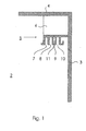
- Figure 1 shows a part of a room 2 at the location of the right-angled joint between a wall 3 and the fixed ceiling 4 of the room 2.
- an extruded hard plastic clamping section 5 Disposed some distance below the ceiling 4 is an extruded hard plastic clamping section 5, which is fixed to the bottom side of a spacer 6, e.g. a wooden strip, with its flat upper side by means of screws (not shown), which spacer 6 is in turn fixed (in a manner not shown) to the ceiling 4 and/or the wall 3.
- the clamping section 5 is practically fully identical to the lath 2 as described in Dutch patent NL 1003163 , to which document reference is made for a more detailed description. Within the context of the present invention if suffices to note that it comprises four downwardly extending slots 7,8,9,10, with the slot 9 being provided with teeth 11.
- the clamping section 5 is provided not only along the entire length of the wall 3 but also along all other walls of the room 2, thus forming an endless whole.
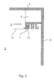
- Figure 2 shows the situation that is obtained after a cloth-like ceiling 12 has been stretched on the inner side of the clamping sections 5. To that end an elongate clamping strip 13 with the edge of the stretch ceiling 12 folded thereover in the form of an upside-down U-shape is clampingly accommodated in the slot 7. Also in this regard the present embodiment is not different, or at least not significantly so, from the embodiment as described in Dutch patent NL 1003163 , to which reference is again made for a more detailed description.
- Figure 3 shows the manner in which subsequently an extruded hard plastic base section 14 is connected to the clamping section 5. To that end and upwardly extending, barbed rib 27 is inserted into the slot 9 of the clamping section 5.
- the base section 14 is U-shaped, seen in vertical cross-sectional view, and is provided with legs 15, 16 having bevelled free ends 17, 18, which extend into the room 2. Although the bevelled ends 17, 18 are spaced apart in figure 2, the end 18 inclines towards the end 17 when no forces are exerted thereon, so that the bevelled portions of the ends 17, 18 join one another in mutually aligned relationship.
- a slot 19 which can be characterised as a clamping slot 19 on account of the fact that the (end 18 of the) leg 16 inclines in the direction of the leg 15.
- the base section 14 is provided with an elastically deformable flange 20.
- the leg 16 is provided with a tooth 21 on the side facing towards the leg 15.
- figure 4 shows the finishing system as it can eventually be used with an extruded hard plastic cover section 22.
- the cover section 22 is shown more or less schematically in figure 4, but as those skilled in the art will appreciate, it may have various forms.
- One condition in the case of the present preferred embodiment, however, is that the cover section 22 be provided with an insertion leg 23 at the upper side thereof, which insertion leg has a free end that extends towards the wall 3.
- a number of teeth 26 are provided on the bottom side of the insertion leg 23, which teeth are intended to mate with the tooth 21 on the leg 16 for the purpose of stabilising the position of the cover section 22 with respect to the base section 14.
- the insertion leg 23 is inserted between the ends 17, 18 of the legs 15, 16 of the base section in the direction indicated by the arrow 28, until the flange 24, which is elastically deformable, abuts against the wall 3.
- the elastically deformable flange 25 abuts against the stretch ceiling 12.
- An important advantage of the present invention is the fact that a higher degree of flexibility is obtained as regards the horizontal position of the cover section 22 with respect to the clamping section 5, so that a proper abutment of the cover section 22 against the wall 3 can be guaranteed also in the case of a relatively strongly inclined position of the wall 3 and/or a great height of the cover section 22.
- the finishing system provides a possibility of easily exchanging the cover 22, if desired, thus making it possible to realise an entirely new appearance.
- clamping section 5 is designed so that it would also be possible not to use a separate cover section 22, and that consequently the clamping section 5 in fact functions as a cover section, in which connection it should be realised that the end 18 of the leg 16 abuts against the end 17 of the legs 15 in unloaded condition, so that no gap that is visible from the room 2 is present therebetween but rather a seam, which will hardly be visible, if at all.
Landscapes
- Engineering & Computer Science (AREA)
- Architecture (AREA)
- Civil Engineering (AREA)
- Structural Engineering (AREA)
- Physics & Mathematics (AREA)
- Electromagnetism (AREA)
- Finishing Walls (AREA)
Abstract
Description
- The present invention relates to a ceiling system comprising horizontal laths mounted in spaced-apart relationship and a ceiling cloth that is stretched between and under said laths, a finishing section for finishing an edge between the ceiling cloth and a wall, and fixing means for fixing said finishing section to the ceiling cloth and to the wall.
- Such a system is described in
Dutch patent NL 1003163 - The object of the present invention is to provide a finishing system as referred to in the introductory paragraph, wherein, whether or not in preferred embodiments of the invention, the aforesaid drawbacks of ceiling systems according to the prior art do not apply, or at least to a significantly smaller extent. In order to accomplish that object, the finishing section comprises a base section, which is fixed to the underside of the ceiling cloth or to the wall by said fixing means, as well as a cover section, which can be connected to the base section by connecting means, in such a manner that the cover section abuts against the ceiling cloth and/or against the wall. Designing the finishing section as a separate base section and a cover section that can be interconnected by means of the base section makes it possible to configure the connection between the base section and the cover section such that the two can readily be manually disconnected from each other without the connection between the base section and the ceiling or a wall being affected.
- A very advantageous embodiment of the connecting means is obtained if the connecting means comprise a clamping slot associated with either one of the base section and the cover section and a clamping wall associated with the other one of the base section and the cover section, which is clampingly inserted into the clamping slot. The connection between the base section and the cover section can thus be effected in a simple manner by inserting the clamping wall into the clamping slot.
- Furthermore preferably, the clamping slot is horizontally oriented. The important advantage of this preferred embodiment is that the cover section can thus be pushed against the wall, making it possible to obtain a proper abutment between the wall and the (underside of the) cover section, even if the latter has a comparatively great height. The present preferred embodiment does not exclude the possibility of using a clamping strip fixed to the wall after all, as is the case with the prior art, in particular in the case of strongly inclined and/or wavy walls, but this will be necessary less soon than is the case with finishing systems according to the prior art. An additional advantage of the use of a horizontally oriented clamping slot is that thus the cover section will not tend to move downwards under the influence of the force of gravity, which might even lead to the connection between the cover section and the base section being broken and the cover section falling on the ground.
- Preferably, the clamping slot and/or the clamping wall is (are) provided with a roughened portion, for example in the form of teeth. Thus it can be ensured that the base section and the cover section will remain correctly positioned relative to each other also in the course of time, which position might be affected by external factors, such as vibrations caused by passing traffic. It will be understood that care must be taken in that case that the roughened portion is not such that it the connection between the base section and the cover section cannot be broken, or only with a great deal of effort, comparable to the connection of the base section to the ceiling or the wall by the fixing means.
- The clamping slot preferably forms part of the base section, so that the clamping wall of the cover section can be inserted into the clamping slot of the base section.
- According to a very practical embodiment, the clamping slot is formed by the space between two at least substantially parallel slot walls, with the free end of one of the slot walls springing towards the other slot wall. As a result, the clamping wall is clamped between the slot walls of the clamping slot to a certain extent. In addition, the presence of the clamping slot can thus be hidden from view in that the free end of the slot wall that is inclined in the direction of the other slot wall can abut against said other slot wall, so that there will be no gap, at most a seam.
- Preferably, the base section abuts both against the ceiling cloth and against the wall, so that it is also suitable for use without a separate cover section, as already indicated in the preceding paragraph.
- Furthermore it is advantageous if the cover section abuts both against the ceiling cloth and against the wall. Thus, the base section would be hidden from view in its entirety by the cover section, so that no special demands need to be made as regards the aesthetic quality of the base section.
- To realise a proper abutment of the cover section and/or the base section against the ceiling cloth or the wall, at least one of the longitudinal edges of the base section and/or the cover section that abut against the ceiling cloth or the wall are formed by a flexible flange edge, such as a rubber or TPE (ThermoPlastic Elastomer).
- Furthermore preferably, the base section is fixed to a lath by the fixing means.
- Even more preferably, the fixing means comprise a clamping recess forming part of either one of the base section and the lath, as well as a clamping rib inserted into the clamping recess, which forms part of the other one of the base section and the lath.
- The clamping rib is preferably vertically oriented, so that the base section can be connected to the lath by pushing the base section upwards against the lath.
- Finally, the invention also relates to a base section as such as well as to a cover section at such for use in a finishing system according to the invention as described above.
- The invention will now be explained in more detail in the description below of a finishing system according to a preferred embodiment of the invention, in which reference is made to the following figures 1-4, which are vertical cross-sectional views of the finishing stages during four successive stages of the mounting thereof.
- Figure 1 shows a part of a
room 2 at the location of the right-angled joint between awall 3 and thefixed ceiling 4 of theroom 2. Disposed some distance below theceiling 4 is an extruded hard plastic clamping section 5, which is fixed to the bottom side of aspacer 6, e.g. a wooden strip, with its flat upper side by means of screws (not shown), whichspacer 6 is in turn fixed (in a manner not shown) to theceiling 4 and/or thewall 3. The clamping section 5 is practically fully identical to thelath 2 as described inDutch patent NL 1003163 slots 7,8,9,10, with the slot 9 being provided withteeth 11. The clamping section 5 is provided not only along the entire length of thewall 3 but also along all other walls of theroom 2, thus forming an endless whole. - Figure 2 shows the situation that is obtained after a cloth-
like ceiling 12 has been stretched on the inner side of the clamping sections 5. To that end anelongate clamping strip 13 with the edge of thestretch ceiling 12 folded thereover in the form of an upside-down U-shape is clampingly accommodated in theslot 7. Also in this regard the present embodiment is not different, or at least not significantly so, from the embodiment as described inDutch patent NL 1003163 - Figure 3 shows the manner in which subsequently an extruded hard plastic base section 14 is connected to the clamping section 5. To that end and upwardly extending,
barbed rib 27 is inserted into the slot 9 of the clamping section 5. The base section 14 is U-shaped, seen in vertical cross-sectional view, and is provided withlegs free ends room 2. Although thebevelled ends end 18 inclines towards theend 17 when no forces are exerted thereon, so that the bevelled portions of theends legs slot 19, which can be characterised as aclamping slot 19 on account of the fact that the (end 18 of the)leg 16 inclines in the direction of theleg 15. To obtain a proper abutment of the base section 14 against thewall 3, the base section 14 is provided with an elasticallydeformable flange 20. Near itsend 18, theleg 16 is provided with atooth 21 on the side facing towards theleg 15. - Finally, figure 4 shows the finishing system as it can eventually be used with an extruded hard
plastic cover section 22. Thecover section 22 is shown more or less schematically in figure 4, but as those skilled in the art will appreciate, it may have various forms. One condition in the case of the present preferred embodiment, however, is that thecover section 22 be provided with aninsertion leg 23 at the upper side thereof, which insertion leg has a free end that extends towards thewall 3. A number of teeth 26 are provided on the bottom side of theinsertion leg 23, which teeth are intended to mate with thetooth 21 on theleg 16 for the purpose of stabilising the position of thecover section 22 with respect to the base section 14. In applied form, theinsertion leg 23 is inserted between theends legs arrow 28, until theflange 24, which is elastically deformable, abuts against thewall 3. In addition to that, the elasticallydeformable flange 25 abuts against thestretch ceiling 12. - An important advantage of the present invention is the fact that a higher degree of flexibility is obtained as regards the horizontal position of the
cover section 22 with respect to the clamping section 5, so that a proper abutment of thecover section 22 against thewall 3 can be guaranteed also in the case of a relatively strongly inclined position of thewall 3 and/or a great height of thecover section 22. In addition to that, the finishing system provides a possibility of easily exchanging thecover 22, if desired, thus making it possible to realise an entirely new appearance. - Furthermore it is important to note that the clamping section 5 is designed so that it would also be possible not to use a
separate cover section 22, and that consequently the clamping section 5 in fact functions as a cover section, in which connection it should be realised that theend 18 of theleg 16 abuts against theend 17 of thelegs 15 in unloaded condition, so that no gap that is visible from theroom 2 is present therebetween but rather a seam, which will hardly be visible, if at all.
Claims (15)
- A ceiling system comprising horizontal laths mounted in spaced-apart relationship and a ceiling cloth that is stretched between and under said laths, a finishing section for finishing an edge between the ceiling cloth and a wall, and fixing means for fixing said finishing section to the ceiling cloth and to the wall, characterised in that the finishing section comprises a base section, which is fixed to the underside of the ceiling cloth or to the wall by said fixing means, as well as a cover section, which can be connected to the base section by connecting means, in such a manner that the cover section abuts against the ceiling cloth and/or against the wall.
- A system according to claim 1, characterised in that the connecting means comprise a clamping slot associated with either one of the base section and the cover section and a clamping wall associated with the other one of the base section and the cover section, which is clampingly inserted into the clamping slot.
- A system according to claim 2, characterised in that the clamping slot is horizontally oriented.
- A system according to claim 2 or 3, characterised in that the clamping slot and/or the clamping wall is (are) provided with a roughened portion, for example in the form of teeth.
- A system according to claim 2, 3 or 4, characterised in that the clamping slot forms part of the base section.
- A system according to claim 2, 3, 4 or 5, characterised in that the clamping slot is formed by the space between two at least substantially parallel slot walls, with the free end of one of the slot walls springing towards the other slot wall.
- A system according to any one of the preceding claims, characterised in that the base section abuts both against the ceiling cloth and against the wall.
- A system according to any one of the preceding claims, characterised in that the cover section abuts both against the ceiling cloth and against the wall.
- A system according to any one of the preceding claims, characterised in that the cover section hides the base section from view in its entirety.
- A system according to any one of the preceding claims, characterised in that at least one of the longitudinal edges of the base section and/or the cover section that abut against the ceiling cloth or the wall are formed by a flexible flange edge.
- A system according to any one of the preceding claims, characterised in that the base section is fixed to a lath by the fixing means.
- A ceiling system according to claim 11, characterised in that the fixing means comprise a clamping recess forming part of either one of the base section and the lath, as well as a clamping rib inserted into the clamping recess, which forms part of the other one of the base section and the lath.
- A ceiling system according to claim 12, characterised in that the clamping rib is vertically oriented.
- A base section for use with a ceiling system according to any one of the preceding claims.
- A cover section for use with a ceiling system according to any one of the claims 1-13.
Applications Claiming Priority (1)
| Application Number | Priority Date | Filing Date | Title |
|---|---|---|---|
| NL1029553A NL1029553C2 (en) | 2005-07-18 | 2005-07-18 | System for finishing an edge between a ceiling and a wall. |
Publications (2)
| Publication Number | Publication Date |
|---|---|
| EP1746215A1 true EP1746215A1 (en) | 2007-01-24 |
| EP1746215B1 EP1746215B1 (en) | 2012-06-13 |
Family
ID=35985486
Family Applications (1)
| Application Number | Title | Priority Date | Filing Date |
|---|---|---|---|
| EP20060076372 Active EP1746215B1 (en) | 2005-07-18 | 2006-07-06 | Ceiling system |
Country Status (3)
| Country | Link |
|---|---|
| EP (1) | EP1746215B1 (en) |
| DK (1) | DK1746215T3 (en) |
| NL (1) | NL1029553C2 (en) |
Cited By (4)
| Publication number | Priority date | Publication date | Assignee | Title |
|---|---|---|---|---|
| NL1037168C2 (en) * | 2009-07-31 | 2011-02-02 | Gerrit Harman Hiddink | SPAN CEILINGS AND CONSTRUCTIONAL CONNECTION DETAILS. |
| WO2012089937A1 (en) * | 2010-12-30 | 2012-07-05 | Normalu | Triple-thickness false wall device |
| EP2610414A1 (en) * | 2011-12-30 | 2013-07-03 | Normalu | Cornice rail |
| EP3205787A1 (en) * | 2016-02-11 | 2017-08-16 | Normalu | Heddle for producing a stretched-fabric false wall made up of two sections assembled in a detachable manner, and false wall comprising such a heddle |
Families Citing this family (1)
| Publication number | Priority date | Publication date | Assignee | Title |
|---|---|---|---|---|
| UA102737U (en) * | 2015-09-17 | 2015-11-10 | PROFILE FOR MOUNTING TILES |
Citations (2)
| Publication number | Priority date | Publication date | Assignee | Title |
|---|---|---|---|---|
| FR2597906A1 (en) * | 1986-04-25 | 1987-10-30 | Bouttier Dominique | Fastening device for a stretched flexible false ceiling |
| NL1003163C2 (en) * | 1996-05-20 | 1997-11-21 | Joseph Spanjers | Ceiling system and slat suitable for such a ceiling system. |
Family Cites Families (2)
| Publication number | Priority date | Publication date | Assignee | Title |
|---|---|---|---|---|
| DE1659736A1 (en) * | 1966-01-20 | 1969-09-18 | Ermecke Ohg Richard | Profiled decorative rails made of plastic or metal for interiors |
| RU2181421C1 (en) * | 2001-05-18 | 2002-04-20 | Торгушников Василий Константинович | Device for fastening of fire-retardant ceiling |
-
2005
- 2005-07-18 NL NL1029553A patent/NL1029553C2/en not_active IP Right Cessation
-
2006
- 2006-07-06 DK DK06076372T patent/DK1746215T3/en active
- 2006-07-06 EP EP20060076372 patent/EP1746215B1/en active Active
Patent Citations (2)
| Publication number | Priority date | Publication date | Assignee | Title |
|---|---|---|---|---|
| FR2597906A1 (en) * | 1986-04-25 | 1987-10-30 | Bouttier Dominique | Fastening device for a stretched flexible false ceiling |
| NL1003163C2 (en) * | 1996-05-20 | 1997-11-21 | Joseph Spanjers | Ceiling system and slat suitable for such a ceiling system. |
Cited By (6)
| Publication number | Priority date | Publication date | Assignee | Title |
|---|---|---|---|---|
| NL1037168C2 (en) * | 2009-07-31 | 2011-02-02 | Gerrit Harman Hiddink | SPAN CEILINGS AND CONSTRUCTIONAL CONNECTION DETAILS. |
| WO2012089937A1 (en) * | 2010-12-30 | 2012-07-05 | Normalu | Triple-thickness false wall device |
| FR2970013A1 (en) * | 2010-12-30 | 2012-07-06 | Normalu | FALSE DEVICE WITH TRIPLE THICKNESS |
| EP2610414A1 (en) * | 2011-12-30 | 2013-07-03 | Normalu | Cornice rail |
| FR2985277A1 (en) * | 2011-12-30 | 2013-07-05 | Normalu | LISSE CORNICHE |
| EP3205787A1 (en) * | 2016-02-11 | 2017-08-16 | Normalu | Heddle for producing a stretched-fabric false wall made up of two sections assembled in a detachable manner, and false wall comprising such a heddle |
Also Published As
| Publication number | Publication date |
|---|---|
| DK1746215T3 (en) | 2012-09-10 |
| NL1029553C2 (en) | 2007-01-19 |
| EP1746215B1 (en) | 2012-06-13 |
Similar Documents
| Publication | Publication Date | Title |
|---|---|---|
| US7975448B2 (en) | Drywall channel with pre-punched locating tabs | |
| CA2997626C (en) | A set comprising panels, a supporting structure and a fastening device | |
| US6494594B1 (en) | Decorative light mounting apparatus | |
| BE1021263B1 (en) | SUPPORT BRACKET FOR SUPPORTING A SLATE OF A GARDEN WIRE PANEL | |
| US11834828B2 (en) | Ceiling suspension system having a coupling bracket with resilient retaining tabs | |
| KR20170008731A (en) | Surface coating and clamp for said coating | |
| CN106460389A (en) | Ceiling system | |
| EP1811098B1 (en) | Ceiling island system | |
| CN1172617C (en) | drawer box | |
| EP1746215B1 (en) | Ceiling system | |
| US11261601B2 (en) | Cross runner connector and cross runner connector arrangement for a suspended ceiling system | |
| US5915848A (en) | Method and apparatus for supporting swimming pool lighting strip | |
| KR102118681B1 (en) | A Deck-road System | |
| GB2251004A (en) | Rainwater gutter | |
| US7269927B2 (en) | Suspended ceiling assembly | |
| EP1961890A1 (en) | A combined set comprising covering elements and attachment elements and a method for mounting said combined set | |
| US6173544B1 (en) | Ceiling system and also a lath suitable for such a ceiling system | |
| US7908821B2 (en) | Post wrap device | |
| US3477186A (en) | Ceiling channel assembly for movable partitions | |
| EP3683377A1 (en) | Insulating frame and method for installing the same | |
| AU759126B2 (en) | Clamping member for clamping a curtain rail | |
| EP0339624A2 (en) | Process for assemblage of self-supporting ceiling panels | |
| CN110662878A (en) | Device for locking two floor panels | |
| US8123231B2 (en) | Seal | |
| US20080041539A1 (en) | Device for Separating Zones of a Room |
Legal Events
| Date | Code | Title | Description |
|---|---|---|---|
| PUAI | Public reference made under article 153(3) epc to a published international application that has entered the european phase |
Free format text: ORIGINAL CODE: 0009012 |
|
| AK | Designated contracting states |
Kind code of ref document: A1 Designated state(s): AT BE BG CH CY CZ DE DK EE ES FI FR GB GR HU IE IS IT LI LT LU LV MC NL PL PT RO SE SI SK TR |
|
| AX | Request for extension of the european patent |
Extension state: AL BA HR MK YU |
|
| 17P | Request for examination filed |
Effective date: 20070713 |
|
| AKX | Designation fees paid |
Designated state(s): AT BE BG CH CY CZ DE DK EE ES FI FR GB GR HU IE IS IT LI LT LU LV MC NL PL PT RO SE SI SK TR |
|
| 17Q | First examination report despatched |
Effective date: 20070913 |
|
| GRAP | Despatch of communication of intention to grant a patent |
Free format text: ORIGINAL CODE: EPIDOSNIGR1 |
|
| GRAS | Grant fee paid |
Free format text: ORIGINAL CODE: EPIDOSNIGR3 |
|
| GRAA | (expected) grant |
Free format text: ORIGINAL CODE: 0009210 |
|
| AK | Designated contracting states |
Kind code of ref document: B1 Designated state(s): AT BE BG CH CY CZ DE DK EE ES FI FR GB GR HU IE IS IT LI LT LU LV MC NL PL PT RO SE SI SK TR |
|
| REG | Reference to a national code |
Ref country code: GB Ref legal event code: FG4D |
|
| REG | Reference to a national code |
Ref country code: AT Ref legal event code: REF Ref document number: 562099 Country of ref document: AT Kind code of ref document: T Effective date: 20120615 Ref country code: CH Ref legal event code: EP |
|
| REG | Reference to a national code |
Ref country code: IE Ref legal event code: FG4D |
|
| REG | Reference to a national code |
Ref country code: DE Ref legal event code: R096 Ref document number: 602006030066 Country of ref document: DE Effective date: 20120809 |
|
| REG | Reference to a national code |
Ref country code: CH Ref legal event code: NV Representative=s name: DR. LUSUARDI AG |
|
| REG | Reference to a national code |
Ref country code: DK Ref legal event code: T3 |
|
| REG | Reference to a national code |
Ref country code: NL Ref legal event code: T3 |
|
| PG25 | Lapsed in a contracting state [announced via postgrant information from national office to epo] |
Ref country code: LT Free format text: LAPSE BECAUSE OF FAILURE TO SUBMIT A TRANSLATION OF THE DESCRIPTION OR TO PAY THE FEE WITHIN THE PRESCRIBED TIME-LIMIT Effective date: 20120613 Ref country code: FI Free format text: LAPSE BECAUSE OF FAILURE TO SUBMIT A TRANSLATION OF THE DESCRIPTION OR TO PAY THE FEE WITHIN THE PRESCRIBED TIME-LIMIT Effective date: 20120613 Ref country code: CY Free format text: LAPSE BECAUSE OF FAILURE TO SUBMIT A TRANSLATION OF THE DESCRIPTION OR TO PAY THE FEE WITHIN THE PRESCRIBED TIME-LIMIT Effective date: 20120613 Ref country code: SE Free format text: LAPSE BECAUSE OF FAILURE TO SUBMIT A TRANSLATION OF THE DESCRIPTION OR TO PAY THE FEE WITHIN THE PRESCRIBED TIME-LIMIT Effective date: 20120613 |
|
| REG | Reference to a national code |
Ref country code: LT Ref legal event code: MG4D Effective date: 20120613 |
|
| PG25 | Lapsed in a contracting state [announced via postgrant information from national office to epo] |
Ref country code: LV Free format text: LAPSE BECAUSE OF FAILURE TO SUBMIT A TRANSLATION OF THE DESCRIPTION OR TO PAY THE FEE WITHIN THE PRESCRIBED TIME-LIMIT Effective date: 20120613 Ref country code: GR Free format text: LAPSE BECAUSE OF FAILURE TO SUBMIT A TRANSLATION OF THE DESCRIPTION OR TO PAY THE FEE WITHIN THE PRESCRIBED TIME-LIMIT Effective date: 20120914 Ref country code: SI Free format text: LAPSE BECAUSE OF FAILURE TO SUBMIT A TRANSLATION OF THE DESCRIPTION OR TO PAY THE FEE WITHIN THE PRESCRIBED TIME-LIMIT Effective date: 20120613 |
|
| PG25 | Lapsed in a contracting state [announced via postgrant information from national office to epo] |
Ref country code: SK Free format text: LAPSE BECAUSE OF FAILURE TO SUBMIT A TRANSLATION OF THE DESCRIPTION OR TO PAY THE FEE WITHIN THE PRESCRIBED TIME-LIMIT Effective date: 20120613 Ref country code: EE Free format text: LAPSE BECAUSE OF FAILURE TO SUBMIT A TRANSLATION OF THE DESCRIPTION OR TO PAY THE FEE WITHIN THE PRESCRIBED TIME-LIMIT Effective date: 20120613 Ref country code: IS Free format text: LAPSE BECAUSE OF FAILURE TO SUBMIT A TRANSLATION OF THE DESCRIPTION OR TO PAY THE FEE WITHIN THE PRESCRIBED TIME-LIMIT Effective date: 20121013 Ref country code: RO Free format text: LAPSE BECAUSE OF FAILURE TO SUBMIT A TRANSLATION OF THE DESCRIPTION OR TO PAY THE FEE WITHIN THE PRESCRIBED TIME-LIMIT Effective date: 20120613 Ref country code: CZ Free format text: LAPSE BECAUSE OF FAILURE TO SUBMIT A TRANSLATION OF THE DESCRIPTION OR TO PAY THE FEE WITHIN THE PRESCRIBED TIME-LIMIT Effective date: 20120613 |
|
| PG25 | Lapsed in a contracting state [announced via postgrant information from national office to epo] |
Ref country code: IT Free format text: LAPSE BECAUSE OF FAILURE TO SUBMIT A TRANSLATION OF THE DESCRIPTION OR TO PAY THE FEE WITHIN THE PRESCRIBED TIME-LIMIT Effective date: 20120613 Ref country code: PL Free format text: LAPSE BECAUSE OF FAILURE TO SUBMIT A TRANSLATION OF THE DESCRIPTION OR TO PAY THE FEE WITHIN THE PRESCRIBED TIME-LIMIT Effective date: 20120613 Ref country code: MC Free format text: LAPSE BECAUSE OF NON-PAYMENT OF DUE FEES Effective date: 20120731 Ref country code: PT Free format text: LAPSE BECAUSE OF FAILURE TO SUBMIT A TRANSLATION OF THE DESCRIPTION OR TO PAY THE FEE WITHIN THE PRESCRIBED TIME-LIMIT Effective date: 20121015 |
|
| PLBE | No opposition filed within time limit |
Free format text: ORIGINAL CODE: 0009261 |
|
| STAA | Information on the status of an ep patent application or granted ep patent |
Free format text: STATUS: NO OPPOSITION FILED WITHIN TIME LIMIT |
|
| PG25 | Lapsed in a contracting state [announced via postgrant information from national office to epo] |
Ref country code: ES Free format text: LAPSE BECAUSE OF FAILURE TO SUBMIT A TRANSLATION OF THE DESCRIPTION OR TO PAY THE FEE WITHIN THE PRESCRIBED TIME-LIMIT Effective date: 20120924 |
|
| REG | Reference to a national code |
Ref country code: IE Ref legal event code: MM4A |
|
| 26N | No opposition filed |
Effective date: 20130314 |
|
| GBPC | Gb: european patent ceased through non-payment of renewal fee |
Effective date: 20120913 |
|
| REG | Reference to a national code |
Ref country code: DE Ref legal event code: R097 Ref document number: 602006030066 Country of ref document: DE Effective date: 20130314 |
|
| PG25 | Lapsed in a contracting state [announced via postgrant information from national office to epo] |
Ref country code: IE Free format text: LAPSE BECAUSE OF NON-PAYMENT OF DUE FEES Effective date: 20120706 Ref country code: BG Free format text: LAPSE BECAUSE OF FAILURE TO SUBMIT A TRANSLATION OF THE DESCRIPTION OR TO PAY THE FEE WITHIN THE PRESCRIBED TIME-LIMIT Effective date: 20120913 Ref country code: GB Free format text: LAPSE BECAUSE OF NON-PAYMENT OF DUE FEES Effective date: 20120913 |
|
| PG25 | Lapsed in a contracting state [announced via postgrant information from national office to epo] |
Ref country code: TR Free format text: LAPSE BECAUSE OF FAILURE TO SUBMIT A TRANSLATION OF THE DESCRIPTION OR TO PAY THE FEE WITHIN THE PRESCRIBED TIME-LIMIT Effective date: 20120613 |
|
| PG25 | Lapsed in a contracting state [announced via postgrant information from national office to epo] |
Ref country code: HU Free format text: LAPSE BECAUSE OF FAILURE TO SUBMIT A TRANSLATION OF THE DESCRIPTION OR TO PAY THE FEE WITHIN THE PRESCRIBED TIME-LIMIT Effective date: 20060706 |
|
| REG | Reference to a national code |
Ref country code: FR Ref legal event code: PLFP Year of fee payment: 10 |
|
| REG | Reference to a national code |
Ref country code: FR Ref legal event code: PLFP Year of fee payment: 11 |
|
| REG | Reference to a national code |
Ref country code: FR Ref legal event code: PLFP Year of fee payment: 12 |
|
| REG | Reference to a national code |
Ref country code: FR Ref legal event code: PLFP Year of fee payment: 13 |
|
| P01 | Opt-out of the competence of the unified patent court (upc) registered |
Effective date: 20230527 |
|
| PGFP | Annual fee paid to national office [announced via postgrant information from national office to epo] |
Ref country code: LU Payment date: 20250721 Year of fee payment: 20 Ref country code: NL Payment date: 20250721 Year of fee payment: 20 |
|
| PGFP | Annual fee paid to national office [announced via postgrant information from national office to epo] |
Ref country code: DK Payment date: 20250725 Year of fee payment: 20 Ref country code: DE Payment date: 20250722 Year of fee payment: 20 |
|
| PGFP | Annual fee paid to national office [announced via postgrant information from national office to epo] |
Ref country code: BE Payment date: 20250721 Year of fee payment: 20 |
|
| PGFP | Annual fee paid to national office [announced via postgrant information from national office to epo] |
Ref country code: FR Payment date: 20250724 Year of fee payment: 20 Ref country code: AT Payment date: 20250722 Year of fee payment: 20 |
|
| PGFP | Annual fee paid to national office [announced via postgrant information from national office to epo] |
Ref country code: CH Payment date: 20250801 Year of fee payment: 20 |