EP1749152B1 - Antriebseinrichtung für eine zweizylinderdickstoffpumpe und verfahren zum betrieb derselben - Google Patents
Antriebseinrichtung für eine zweizylinderdickstoffpumpe und verfahren zum betrieb derselben Download PDFInfo
- Publication number
- EP1749152B1 EP1749152B1 EP05733928A EP05733928A EP1749152B1 EP 1749152 B1 EP1749152 B1 EP 1749152B1 EP 05733928 A EP05733928 A EP 05733928A EP 05733928 A EP05733928 A EP 05733928A EP 1749152 B1 EP1749152 B1 EP 1749152B1
- Authority
- EP
- European Patent Office
- Prior art keywords
- cylinder
- drive
- fluid
- supply line
- cylinders
- Prior art date
- Legal status (The legal status is an assumption and is not a legal conclusion. Google has not performed a legal analysis and makes no representation as to the accuracy of the status listed.)
- Expired - Lifetime
Links
Images

Classifications
-
- F—MECHANICAL ENGINEERING; LIGHTING; HEATING; WEAPONS; BLASTING
- F04—POSITIVE - DISPLACEMENT MACHINES FOR LIQUIDS; PUMPS FOR LIQUIDS OR ELASTIC FLUIDS
- F04B—POSITIVE-DISPLACEMENT MACHINES FOR LIQUIDS; PUMPS
- F04B15/00—Pumps adapted to handle specific fluids, e.g. by selection of specific materials for pumps or pump parts
- F04B15/02—Pumps adapted to handle specific fluids, e.g. by selection of specific materials for pumps or pump parts the fluids being viscous or non-homogeneous
-
- F—MECHANICAL ENGINEERING; LIGHTING; HEATING; WEAPONS; BLASTING
- F04—POSITIVE - DISPLACEMENT MACHINES FOR LIQUIDS; PUMPS FOR LIQUIDS OR ELASTIC FLUIDS
- F04B—POSITIVE-DISPLACEMENT MACHINES FOR LIQUIDS; PUMPS
- F04B7/00—Piston machines or pumps characterised by having positively-driven valving
- F04B7/0019—Piston machines or pumps characterised by having positively-driven valving a common distribution member forming a single discharge distributor for a plurality of pumping chambers
- F04B7/0026—Piston machines or pumps characterised by having positively-driven valving a common distribution member forming a single discharge distributor for a plurality of pumping chambers and having an oscillating movement
-
- F—MECHANICAL ENGINEERING; LIGHTING; HEATING; WEAPONS; BLASTING
- F04—POSITIVE - DISPLACEMENT MACHINES FOR LIQUIDS; PUMPS FOR LIQUIDS OR ELASTIC FLUIDS
- F04B—POSITIVE-DISPLACEMENT MACHINES FOR LIQUIDS; PUMPS
- F04B15/00—Pumps adapted to handle specific fluids, e.g. by selection of specific materials for pumps or pump parts
- F04B15/02—Pumps adapted to handle specific fluids, e.g. by selection of specific materials for pumps or pump parts the fluids being viscous or non-homogeneous
- F04B15/023—Pumps adapted to handle specific fluids, e.g. by selection of specific materials for pumps or pump parts the fluids being viscous or non-homogeneous supply of fluid to the pump by gravity through a hopper, e.g. without intake valve
-
- F—MECHANICAL ENGINEERING; LIGHTING; HEATING; WEAPONS; BLASTING
- F04—POSITIVE - DISPLACEMENT MACHINES FOR LIQUIDS; PUMPS FOR LIQUIDS OR ELASTIC FLUIDS
- F04B—POSITIVE-DISPLACEMENT MACHINES FOR LIQUIDS; PUMPS
- F04B7/00—Piston machines or pumps characterised by having positively-driven valving
- F04B7/02—Piston machines or pumps characterised by having positively-driven valving the valving being fluid-actuated
-
- F—MECHANICAL ENGINEERING; LIGHTING; HEATING; WEAPONS; BLASTING
- F04—POSITIVE - DISPLACEMENT MACHINES FOR LIQUIDS; PUMPS FOR LIQUIDS OR ELASTIC FLUIDS
- F04B—POSITIVE-DISPLACEMENT MACHINES FOR LIQUIDS; PUMPS
- F04B9/00—Piston machines or pumps characterised by the driving or driven means to or from their working members
- F04B9/08—Piston machines or pumps characterised by the driving or driven means to or from their working members the means being fluid
- F04B9/10—Piston machines or pumps characterised by the driving or driven means to or from their working members the means being fluid the fluid being liquid
- F04B9/109—Piston machines or pumps characterised by the driving or driven means to or from their working members the means being fluid the fluid being liquid having plural pumping chambers
- F04B9/117—Piston machines or pumps characterised by the driving or driven means to or from their working members the means being fluid the fluid being liquid having plural pumping chambers the pumping members not being mechanically connected to each other
- F04B9/1176—Piston machines or pumps characterised by the driving or driven means to or from their working members the means being fluid the fluid being liquid having plural pumping chambers the pumping members not being mechanically connected to each other the movement of each piston in one direction being obtained by a single-acting piston liquid motor
- F04B9/1178—Piston machines or pumps characterised by the driving or driven means to or from their working members the means being fluid the fluid being liquid having plural pumping chambers the pumping members not being mechanically connected to each other the movement of each piston in one direction being obtained by a single-acting piston liquid motor the movement in the other direction being obtained by a hydraulic connection between the liquid motor cylinders
-
- F—MECHANICAL ENGINEERING; LIGHTING; HEATING; WEAPONS; BLASTING
- F04—POSITIVE - DISPLACEMENT MACHINES FOR LIQUIDS; PUMPS FOR LIQUIDS OR ELASTIC FLUIDS
- F04B—POSITIVE-DISPLACEMENT MACHINES FOR LIQUIDS; PUMPS
- F04B2203/00—Motor parameters
- F04B2203/09—Motor parameters of linear hydraulic motors
- F04B2203/0903—Position of the driving piston
Definitions
- the present invention relates to a method for operating a two-cylinder high-pressure pump or a drive device for a two-cylinder high-pressure pump according to the preamble of claim 1 or the preamble of claim 9.
- Two-cylinder high-pressure pumps are used, for example, for conveying concrete.
- the concrete z. B. pumped via appropriate distribution booms on significant heights and distances.
- the delivery cylinders are connected via a switch, in particular a diverter valve to a common delivery line, wherein the switch alternately connects one or the other delivery cylinder with the delivery line, so that overall results in a nearly continuous flow of the thick material or concrete.
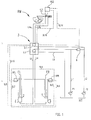
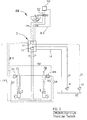
- FIG. 2 shows a hydraulic drive for a two-cylinder high-pressure pump with a pipe switch.
- the block diagram shown is a so-called single-circle system in which the drive cylinders 1, 2 of the delivery cylinders FR, FL and the setting cylinders SZ of the transfer tube are supplied with hydraulic oil only by means of a supply device or the working pressure is generated.
- This single supply device has two pumps P1 and P2, which are connected via the oil lines L1 and L2 with a switching block 3, depending on the operating state, the pumped by the pumps P1 and P2 oil via lines L4 the one drive cylinder 1 or the drive cylinder 2 for the delivery cylinder FR and FL or via further lines L4a the adjusting or swivel cylinder SZ of the pipe switch RW is available.
- Two-circuit system to realize (s. Fig. 3 ), in which the pumps P1 and P2 are provided separately for the drive cylinders 1 and 2 of the delivery cylinders FR and FL on the one hand and for the adjusting or swivel cylinder SZ of the transfer tube RW on the other hand.
- the pumps P1 and P2 are provided separately for the drive cylinders 1 and 2 of the delivery cylinders FR and FL on the one hand and for the adjusting or swivel cylinder SZ of the transfer tube RW on the other hand.
- two independent pumping devices each with at least one pump P 1 and P2, ie a so-called.
- Two-circuit system is provided. This makes it possible to operate the delivery cylinder and the adjusting cylinder or time parallel to shorten the delivery interruption.
- the disadvantage here is that two separate pumping devices must be present, in particular, the pump P1 must be designed to be correspondingly large in order to provide the necessary hydraulic oil volume flow for the operation of the drive cylinder 1 and 2 available.
- the invention is based on the recognition that in a drive of the drive cylinder or delivery cylinder of a two-cylinder high-pressure pump by means of a fluid, in particular a hydraulic oil, in the end region of the piston movement, ie at the end of a piston stroke no longer full drive power is needed. Based on this knowledge, it is then possible to shorten the switching time by using the no longer required drive power, that the drive power is no longer required already for the operation of the switch, especially for the drive of a pan or actuator cylinder for a pipe switch use. Thus, it is no longer necessary to wait until the piston stroke in the drive or delivery cylinder has ended, but the switching process and thus the operation of the transfer tube can be initiated already before the end of a piston stroke.
- a fluid in particular a hydraulic oil
- the invention provides to monitor or determine the position of the piston in the drive cylinder or delivery cylinder and determine at least in a certain position shortly before reaching the end position, so that starting from this information, a portion of the fluid volume flow, preferably hydraulic oil flow for the actuation of the adjusting or pivoting cylinder of the switch can be provided.
- the determination device used therefor can be of a mechanical, electrical or hydraulic nature, with the latter in particular offering itself when the entire control of the drive largely takes place by means of a fluid or hydraulic oil. Namely, corresponding switching valves can be used in a simple manner, which are controlled via known hydraulic control lines.
- a corresponding detection device for detecting the piston position of the adjusting cylinder of the pipe switch may be provided to use this information for the switching operation.
- the hydraulic circuit can be constructed so that two pumping devices used to provide a corresponding fluid flow or operating pressure are used, which are comparable to the two-circuit system primarily independent on the one hand for driving the drive cylinder and on the other hand for driving the actuating or pivoting cylinder for the switch. Due to the inventive idea that shortly before the required switching operation of the switch, the drive power for the drive or delivery cylinder no longer must be 100%, the two independent pumping devices can be combined in such a way that during the piston stroke of the drive cylinder or Delivery cylinder, the second pumping device provides their capacity for the drive or delivery cylinder available, while shortly before the switching operation, the second pumping means is used exclusively for the actuation of the actuating or pivoting cylinder of the switch. In this way, it is possible to effectively use the pumping or delivery of the drive or to use components with lower power.
- the drive is designed so that the operating pressure in particular of the second pumping device is present during the entire operation of the actuating or swivel cylinder.
- the deflection of the fluid volume flow can be realized in a simple manner by a corresponding switching valve, so that the circuit complexity can be kept very low overall.
- Fig. 1 shows a block diagram of a hydraulic drive of a two-cylinder high-pressure pump with a first drive cylinder 1 and a second drive cylinder 2, which are connected via the respective pistons with a first delivery cylinder FR and a second delivery cylinder FL.
- the delivery cylinders FL and FR are connected via a pipe switch RW to a common delivery line, so that a nearly continuous delivery rate for the thick material is achieved by the alternating stroke of the delivery cylinders FL and FR.
- the pipe switch RW must be alternately brought into a connecting position between the first conveyor cylinder FR and the common conveyor line or second conveyor cylinder FL and common conveyor line via a control or swivel cylinder SZ.
- two pumping devices P1 and P2 are provided, each of which may have one or more pumps connected in parallel. In the block diagram shown only one pump is shown for each pumping device.
- the pumping devices P1 and P2 are connected via the supply lines L1 and L2 to the control block 3, are received in the switching valves 3.1 and 3.2, which in turn are connected to the hydraulic lines L4 and L4a.
- an intermediate line for mutual connection is provided, in which a switching valve 6 is installed, so that hydraulic oil, which is conveyed in the supply line L1 through the first pumping device P1 can be pumped into the second supply line L2.
- the switching valve 6 has the task that hydraulic oil, which is pumped by the second pumping device P2 in the supply line L2, to maintain a sufficient oil flow to actuate the drive cylinders 1 and 2 can pass into the first supply line L1.
- the hydraulic oil in the supply line L1 is then alternately through the switching valve 3.2 via the supply lines L4 the first drive cylinder 1 and the second drive cylinder 2 provided to operate on these the delivery cylinders FR and FL. Via the line L9 the oil return occurs.
- switching valves VFR and VFL are provided, by means of which the alternating stroke movement of the drive cylinders 1 and 2 is controlled. Because of the alternating stroke movement of the drive cylinders 1 and 2, these are hydraulically coupled to one another via the control lines SL5, SL6, SL7 and SL9.
- the switching valves VFR and VFL also simultaneously form so-called proximity switches, by means of which the piston position in the drive cylinders 1 and 2 can be determined. At the same time are acted upon by the corresponding positions of the piston in the drive cylinders 1 and 2 connected to the switching valves VFR and VFL control lines SL8 and SL10, which in turn control the switching valves 3.1 and 3.2 in the control block 3 and the switching valve 6 accordingly.
- the diverter when changing the delivery stroke from the delivery cylinder FR to the delivery cylinder FL or vice versa, the diverter must be operated by the adjusting or swivel cylinder SZ accordingly.
- the actuating cylinder SZ is supplied via the switching valve 3.1 through the second pumping device P2 and the supply lines L2 and L4a with corresponding hydraulic oil or pressurized.
- the switching valve 6 is triggered by the hydraulic signals by means of the control lines SL8 and SL10, the switching valve 3.1 and the switching valve 6 are switched over the switching valve 6 before reaching the respective Kolbenend ein the drive cylinder 1 or 2 accordingly.
- the switching valve 6 in this case blocks the connecting line between the supply lines L1 and L2 in such a way that no more oil flow from the supply line L2 in the supply line L1 and thus can reach the supply of the drive cylinder 1 and 2. Rather, the delivery rate of the second pumping device P2 is completely provided to the swivel cylinder SZ, wherein by the corresponding hydraulic control lines SL18 and SL19 and the switching valve VSZ for controlling the actuating or
- Swivel cylinder SZ is actuated or this outputs corresponding control signals to the changeover valve 6.
- the oil volume flow which is usually used by the second pumping device P2 for the actuation of the drive cylinders 1 and 2, in the final movement of the respective drive cylinders 1 and 2, in which this volume flow is not absolutely necessary, early for an actuation of the pivoting cylinder can be used, so that the delivery interruption of the slurry pump is reduced.
- the second pumping device P2 is connected via the supply line L2 directly to the switching valve 3.1 or via the hydraulic lines L4a to the swivel or actuating cylinder SZ, the operating pressure of the second pumping device P2 is available to the swivel cylinder SZ during the entire operation.
Landscapes
- Engineering & Computer Science (AREA)
- Mechanical Engineering (AREA)
- General Engineering & Computer Science (AREA)
- Reciprocating Pumps (AREA)
- Fluid-Pressure Circuits (AREA)
- Jet Pumps And Other Pumps (AREA)
Description
- Die vorliegende Erfindung betrifft ein Verfahren zum Betreiben einer Zweizylinderdickstoffpumpe bzw. eine Antriebseinrichtung für eine Zweizylinderdickstoffpumpe nach dem Oberbegriff des Anspruchs 1 bzw. dem Oberbegriff des Anspruchs 9.
- Zweizylinderdickstoffpumpen werden beispielsweise zur Förderung von Beton eingesetzt. Hierbei wird der Beton z. B. über entsprechende Verteilermaste über erhebliche Höhen und Entfernungen gepumpt. Bei derartigen Zweizylinderdickstoffpumpen sind die Förderzylinder über eine Weiche, insbesondere eine Rohrweiche an eine gemeinsame Förderleitung angeschlossen, wobei die Weiche abwechselnd den einen oder anderen Förderzylinder mit der Förderleitung verbindet, so dass sich insgesamt ein nahezu kontinuierlicher Fluss des Dickstoffmaterials bzw. Betons ergibt.
- Durch den unvermeidlichen Anschlusswechsel der Förderzylinder an die gemeinsame Förderleitung mittels der Weiche ergeben sich jedoch bei den Schaltvorgängen kurzfristige Förderunterbrechungen.
- Dies ist beispielsweise aus dem Blockschaltbild der
Fig. 2 zu erkennen, welches einen Hydraulikantrieb für eine Zweizylinderdickstoffpumpe mit einer Rohrweiche zeigt. Bei dem gezeigten Blockschaltbild handelt es sich um ein sog. Einkreissystem, bei dem die Antriebszylinder 1, 2 der Förderzylinder FR, FL sowie der Stellzylinder SZ der Rohrweiche nur mittels einer Versorgungseinrichtung mit Hydrauliköl versorgt werden bzw. der Arbeitsdruck erzeugt wird. Diese einzige Versorgungseinrichtung weist zwei Pumpen P1 und P2 auf, die über die Ölleitungen L1 und L2 mit einem Schaltblock 3 verbunden sind, der je nach Betriebszustand das von den Pumpen P1 und P2 geförderte Öl über Leitungen L4 dem einen Antriebszylinder 1 oder dem Antriebszylinder 2 für die Förderzylinder FR und FL oder über weitere Leitungen L4a dem Stell- bzw. Schwenkzylinder SZ der Rohrweiche RW zur Verfügung stellt. - Hier kommt es jedoch zu relativ langen Schaltvorgängen, da erst nach Beendigung eines Kolbenhubs des Antriebszylinders 1 oder 2 der Steuerblock 3 so geschaltet wird, dass die gesamte Förderleistung der Pumpen P1 und P2 dem Stell- bzw. Schwenkzylinder SZ zur Verfügung gestellt wird.
- Erst nach dem Verschwenken der Rohrweiche durch Betätigung des Stell- bzw. Schwenkzylinders SZ wird dann durch ein Umschalten im Steuerblock 3 die gesamte Förderleistung der Pumpen P 1 und P2 wieder den Antriebszylindern 1 oder 2 zur Verfügung gestellt.
- Um derartige lange Schaltzeiten zu vermeiden, ist es aus dem Stand der Technik bekannt, ein sog. Zweikreissystem zu verwirklichen (s.
Fig. 3 ), bei dem die Pumpen P1 und P2 getrennt für die Antriebszylinder 1 und 2 der Förderzylinder FR und FL einerseits sowie für den Stell- bzw. Schwenkzylinder SZ der Rohrweiche RW andererseits vorgesehen sind. Somit sind hier zwei unabhängige Pumpeinrichtungen mit jeweils mindestens einer Pumpe P 1 und P2, also ein sog. Zweikreissystem vorgesehen. Damit ist es möglich, die Förderzylinder und den oder die Stellzylinder zeitparallel zu betätigen um die Förderunterbrechung zu verkürzen. - Allerdings besteht hierbei der Nachteil darin, dass zwei getrennte Pumpeinrichtungen vorhanden sein müssen, wobei insbesondere die Pumpe P1 entsprechend groß ausgelegt werden muss, um den nötigen Hydraulikölvolumenstrom für den Betrieb der Antriebszylinder 1 und 2 zur Verfügung stellen zu können.
- Pumpen und Verfahren der betreffenden Art sind beispielsweise aus den Patentschriften
DE 195 03 986 A1 undDE 195 31 358 A1 , sowie insbesondere aus derDE 92 17 574 U1 bekannt. - Es ist Aufgabe der vorliegenden Erfindung eine schnelle Umschaltung der Weiche für die Anbindung der zwei Förderzylinder an die gemeinsame Förderleitung zu gewährleisten, wobei der schaltungstechnische Aufwand und der Aufwand für den Hydraulikantrieb der Antriebs- bzw. Förderzylinder und des Stellzylinders für die Weiche möglichst gering gehalten werden soll.
- Diese Aufgabe wird gelöst durch ein Verfahren bzw. eine Zweizylinder-Dickstoffpumpe mit den Merkmalen der Ansprüche 1 bzw. 9. Vorteilhafte Ausgestaltungen sind Gegenstand der abhängigen Ansprüche.
- Die Erfindung geht aus von der Erkenntnis, dass bei einem Antrieb der Antriebszylinder bzw. Förderzylinder einer Zweizylinderdickstoffpumpe mittels eines Fluids, insbesondere eines Hydrauliköls, im Endbereich der Kolbenbewegung, also am Ende eines Kolbenhubs nicht mehr die volle Antriebsleistung benötigt wird. Aufgrund dieser Erkenntnis ist es dann möglich durch Verwendung der nicht mehr benötigten Antriebsleistung die Schaltzeit dadurch zu verkürzen, dass die nicht mehr benötigte Antriebsleistung bereits für die Betätigung der Weiche, insbesondere für den Antrieb eines Schwenk- bzw. Stellzylinders für eine Rohrweiche Verwendung finden kann. Damit muss nicht mehr abgewartet werden, bis der Kolbenhub im Antriebs- bzw. Förderzylinder beendet ist, sondern es kann der Schaltvorgang und somit die Betätigung der Rohrweiche bereits vor Ende eines Kolbenhubs eingeleitet werden.
- Zu diesem Zweck ist erfindungsgemäß vorgesehen, die Stellung des Kolbens im Antriebszylinder bzw. Förderzylinder zu überwachen bzw. zu ermitteln und zumindest in einer bestimmten Stellung kurz vor dem Erreichen der Endstellung festzustellen, so dass ausgehend von dieser Information ein Teil des Fluidvolumenstroms, vorzugsweise Hydraulikölvolumenstroms für die Betätigung des Stell- bzw. Schwenkzylinders der Weiche zur Verfügung gestellt werden kann.
- Die dafür verwendete Ermittlungseinrichtung kann mechanischer, elektrischer oder hydraulischer Art sein, wobei sich letzteres insbesondere anbietet, wenn die gesamte Steuerung des Antriebs weitgehend mittels eines Fluids bzw. Hydrauliköls erfolgt. Es können dann nämlich in einfacher Weise entsprechende Schaltventile eingesetzt werden, die über bekannte hydraulische Steuerleitungen angesteuert werden.
- Ferner kann bei einer bevorzugten Ausführungsform eine entsprechende Erfassungseinrichtung zur Erfassung der Kolbenlage des Stellzylinders der Rohrweiche vorgesehen sein, um diese Information für den Schaltvorgang zu nutzen.
- Vorzugsweise kann die hydraulische Schaltung so aufgebaut sein, dass zwei Pumpeinrichtungen zur Bereitstellung eines entsprechenden Fluidstroms bzw. Betriebsdrucks eingesetzt werden, die vergleichbar dem Zweikreissystem primär unabhängig einerseits für den Antrieb der Antriebszylinder und andererseits für den Antrieb des Stell- bzw. Schwenkzylinders für die Weiche eingesetzt werden. Auf Grund der erfindungsgemäßen Idee, dass kurz vor dem erforderlichen Schaltvorgang der Weiche die Antriebsleistung für die Antriebs- bzw. Förderzylinder nicht mehr 100 % betragen muss, können die beiden unabhängigen Pumpeinrichtungen in der Weise miteinander kombiniert werden, dass während des Kolbenhubs des Antriebszylinders bzw. Förderzylinders die zweite Pumpeinrichtung ihre Förderleistung für die Antriebs- bzw. Förderzylinder zur Verfügung stellt, während kurz vor dem Schaltvorgang die zweite Pumpeinrichtung ausschließlich für die Betätigung des Stell- bzw. Schwenkzylinders der Weiche eingesetzt wird. Auf diese Weise ist es möglich, die Pump- bzw. Förderleistung des Antriebs effektiv einzusetzen bzw. Komponenten mit geringerer Leistung zu verwenden.
- Vorzugsweise ist der Antrieb so gestaltet, dass der Betriebsdruck insbesondere der zweiten Pumpeinrichtung während des gesamten Betriebes an dem Stell- bzw. Schwenkzylinder ansteht.
- Die Umlenkung des Fluidvolumenstroms kann in einfacher Weise durch ein entsprechendes Schaltventil realisiert werden, so dass der schaltungstechnische Aufwand insgesamt sehr gering gehalten werden kann.
- Obwohl die Erfindung nachfolgend am Beispiel eines Hydraulikantriebs mit Hydrauliköl als Fluid beschrieben ist, ist es selbstverständlich, dass die Erfindung auch mit anderen geeigneten Fluiden und entsprechenden Einrichtungen zur Druckerzeugung und/oder Förderung des Fluids möglich ist.
- Weitere Vorteile, Kennzeichen und Merkmale der vorliegenden Erfindung werden bei der nachfolgenden detaillierten Beschreibung eines Ausführungsbeispiels anhand der beigefügten Zeichnungen deutlich. Die Zeichnungen zeigen dabei in rein schematischer Weise
- Fig. 1
- ein Blockschaltbild einer erfindungsgemäßen Antriebseinrichtung;
- Fig. 2
- ein Blockschaltbild eines bekannten Einkreissystems; und in
- Fig. 3
- ein Blockschaltbild eines bekannten Zweikreissystems.
-
Fig. 1 zeigt ein Blockschaltbild eines Hydraulikantriebs einer Zweizylinderdickstoffpumpe mit einem ersten Antriebszylinder 1 und einem zweiten Antriebszylinder 2, die über die entsprechenden Kolben mit einem ersten Förderzylinder FR und einem zweiten Förderzylinder FL verbunden sind. - Die Förderzylinder FL und FR werden über eine Rohrweiche RW an eine gemeinsame Förderleitung angeschlossen, so dass durch den abwechselnden Hub der Förderzylinder FL und FR eine nahezu kontinuierliche Förderleistung für den Dickstoff erzielt wird. Zu diesem Zweck muss die Rohrweiche RW über einen Stell- bzw. Schwenkzylinder SZ abwechselnd in eine Verbindungsstellung zwischen erstem Förderzylinder FR und gemeinsamer Förderleitung bzw. zweitem Förderzylinder FL und gemeinsamer Förderleitung gebracht werden.
- Zur Versorgung des Hydraulikantriebs sind zwei Pumpeinrichtungen P1 und P2 vorgesehen, die jeweils für sich ein oder mehrere parallel geschaltete Pumpen aufweisen können. Im gezeigten Blockschaltbild ist für jede Pumpeinrichtung jeweils nur eine Pumpe dargestellt. Die Pumpeinrichtungen P1 und P2 sind über die Versorgungsleitungen L1 und L2 mit dem Steuerblock 3 verbunden, in dem Schaltventile 3.1 und 3.2 aufgenommen sind, die wiederum mit den Hydraulikleitungen L4 und L4a verbunden sind.
- Zwischen den Versorgungsleitungen L1 und L2 ist eine Zwischenleitung zur gegenseitigen Verbindung vorgesehen, in der ein Schaltventil 6 eingebaut ist, so dass Hydrauliköl, das in der Versorgungsleitung L1 durch die erste Pumpeinrichtung P1 gefördert wird in die zweite Versorgungsleitung L2 gepumpt werden kann. Insbesondere hat das Schaltventil 6 jedoch die Aufgabe, dass Hydrauliköl, das von der zweiten Pumpeinrichtung P2 in der Versorgungsleitung L2 gepumpt wird, zur Aufrechterhaltung eines ausreichenden Ölstroms zur Betätigung der Antriebszylinder 1 und 2 in die erste Versorgungsleitung L1 übertreten kann.
- Das Hydrauliköl in der Versorgungsleitung L1 wird dann durch das Schaltventil 3.2 jeweils abwechselnd über die Versorgungsleitungen L4 dem ersten Antriebszylinder 1 bzw. dem zweiten Antriebszylinder 2 zur Verfügung gestellt, um über diese die Förderzylinder FR und FL zu betätigen. Über die Leitung L9 erfolgt der Ölrückfluss.
- An den Antriebszylindern 1 und 2 sind Schaltventile VFR und VFL vorgesehen, mittels der die abwechselnde Hubbewegung der Antriebszylinder 1 und 2 gesteuert wird. Wegen der abwechselnden Hubbewegung der Antriebszylinder 1 und 2 sind diese hydraulisch über die Steuerleitungen SL5, SL6, SL7 und SL9 miteinander gekoppelt.
- Die Schaltventile VFR und VFL bilden gleichzeitig auch sog. Näherungsschalter, mittels derer die Kolbenstellung in den Antriebszylindern 1 und 2 ermittelt werden kann. Gleichzeitig werden durch die entsprechenden Stellungen des Kolbens in den Antriebszylindern 1 und 2 die an den Schaltventilen VFR und VFL angeschlossenen Steuerleitungen SL8 und SL10 entsprechend beaufschlagt, die wiederum die Schaltventile 3.1 und 3.2 im Steuerblock 3 bzw. das Umschaltventil 6 entsprechend ansteuern.
- Dies erfolgt in der Weise, dass bei einem Wechsel des Förderhubs vom Förderzylinder FR zum Förderzylinder FL oder umgekehrt auch die Rohrweiche entsprechend durch den Stell- bzw. Schwenkzylinder SZ betätigt werden muss. Zu diesem Zweck wird der Stellzylinder SZ über das Schaltventil 3.1 durch die zweite Pumpeinrichtung P2 und die Versorgungsleitungen L2 und L4a mit entsprechendem Hydrauliköl versorgt bzw. mit Druck beaufschlagt. Um eine möglichst schnelle Schaltung zu ermöglichen, wird über das Schaltventil 6 vor Erreichen der jeweiligen Kolbenendstellung des Antriebszylinders 1 oder 2 ausgelöst durch die hydraulischen Signale mittels der Steuerleitungen SL8 und SL10, das Schaltventil 3.1 und das Umschaltventil 6 entsprechend geschaltet.
- Das Umschaltventil 6 sperrt hierbei die Verbindungsleitung zwischen den Versorgungsleitungen L1 und L2 in der Weise ab, dass kein Ölstrom mehr von der Versorgungsleitung L2 in die Versorgungsleitung L1 und damit zur Versorgung der Antriebszylinder 1 und 2 gelangen kann. Vielmehr wird die Förderleistung der zweiten Pumpeinrichtung P2 vollständig dem Schwenkzylinder SZ bereitgestellt, wobei durch die entsprechenden hydraulischen Steuerleitungen SL18 und SL19 auch das Schaltventil VSZ zur Steuerung des Stell- bzw.
- Schwenkzylinders SZ betätigt wird bzw. dieses entsprechende Steuersignale an das Umschaltventil 6 abgibt.
- Durch den Einsatz des Umschaltventils 6 kann der Ölvolumenstrom, der durch die zweite Pumpeinrichtung P2 üblicherweise für die Betätigung der Antriebszylinder 1 und 2 mit verwendet wird, in der Endbewegung der jeweiligen Antriebszylinder 1 und 2, in der dieser Volumenstrom nicht unbedingt erforderlich ist, frühzeitig für eine Betätigung des Schwenkzylinders eingesetzt werden, so dass die Förderunterbrechung der Dickstoffpumpe verringert wird.
- Da darüber hinaus die zweite Pumpeinrichtung P2 über die Versorgungsleitung L2 direkt mit dem Schaltventil 3.1 bzw. über die Hydraulikleitungen L4a mit dem Schwenk- oder Stellzylinder SZ verbunden ist, steht der Betriebsdruck der zweiten Pumpeinrichtung P2 während des gesamten Betriebs unmittelbar dem Schwenkzylinder SZ zur Verfügung.
- Bei dem gezeigten Ausführungsbeispiel handelt es sich somit um eine vorteilhafte Kombination eines Einkreis- und eines Zweikreissystems, bei dem die Förderleistung der zweiten Pumpeinrichtung variabel sowohl für die Betätigung der Antriebszylinder 1 und 2 als auch des Schwenk- bzw. Stellzylinders SZ Verwendung findet. Insbesondere am Ende einer Hubbewegung, bei dem nicht die gesamte Förderleistung der Pumpeinrichtungen für die Betätigung des Antriebszylinders bis in die Endstellung erforderlich ist, ergibt sich somit die vorteilhafte Möglichkeit bereits einen Teil des Ölvolumenstroms für die Betätigung des Stell- bzw. Schwenkzylinders der Rohrweiche bereitzustellen, um damit eine Verkürzung der Förderstromunterbrechung auf ein Minimum zu bewirken.
Claims (11)
- Verfahren zum Betreiben einer Zweizylinder-Dickstoffpumpe, vorzugsweise zur Förderung von Beton, mit zwei abwechselnd betätigten Förderzylindern (FL, FR), die über eine Weiche (RW) eine gemeinsame Förderleitung mit Dickstoff beschicken, wobei die Förderzylinder (FR, FL) mittels eines Fluids über Antriebszylinder (1, 2) betätigt werden und die Weiche (RW) ebenfalls mittels eines Fluids über einen Stellzylinder (SZ) betätigt wird, wobei eine erste Pumpeneinrichtung (P1) vorgesehen ist, deren Fluidvolumenstrom mittels einer ersten Versorgungsleitung (L1) primär den Antriebszylindern (1, 2) zur Verfügung gestellt wird und eine zweite Pumpeneinrichtung (P2), deren Fluidvolumenstrom mittels einer zweiten Versorgungsleitung (L2) primär dem Stellzylinder (SZ) zur Verfügung gestellt wird,
dadurch gekennzeichnet, dass
während des Kolbenhubs eines Antriebszylinders (1, 2) zumindest ein Teil des Fluidvolumenstroms der zweiten Pumpeinrichtung (P2) zum Fluidvolumenstrom der ersten Pumpeneinrichtung (P1) für die Antriebszylinder (1, 2) übertritt. - Verfahren nach Anspruch 1,
dadurch gekennzeichnet, dass
der Fluidvolumenstrom in der zweiten Versorgungsleitung zum Schwenkzylinder (L2) oder ein Teil davon, über eine Zwischenleitung, in der eine Umschalteinrichtung eingebaut ist, in die erste Versorgungsleitung zu den Antriebszylindern (L1) übertreten kann. - Verfahren nach Anspruch 1 oder Anspruch 2,
dadurch gekennzeichnet, dass
der Fluidvolumenstrom in der ersten Versorgungsleitung (L1) durch ein Schaltventil (3.2) jeweils abwechselnd dem ersten Antriebszylinder (1) bzw. dem zweiten Antriebszylinder (2) zur Verfügung gestellt wird. - Verfahren nach einem der vorherigen Ansprüche,
dadurch gekennzeichnet, dass
kurz vor dem Erreichen der Endstellung eines Antriebszylinders (1, 2) die Umschalteinrichtung die Zwischenleitung zwischen den Versorgungsleitungen (L1) und (L2) sperrt, so dass kein Fluidvolumenstrom mehr von der zweiten Versorgungsleitung (L2) in die erste Versorgungsleitung (L1) übertreten kann. - Verfahren nach einem der vorherigen Ansprüche,
dadurch gekennzeichnet, dass
die Kolbenendstellung in den Antriebszylindern (1, 2) mittels Näherungsschalter ermittelt wird, um die Umschalteinrichtung entsprechend anzusteuern. - Verfahren nach einem der vorherigen Ansprüche,
dadurch gekennzeichnet, dass
der Fluidvolumenstrom von einer Pumpeneinrichtung (P1, P2) von jeweils einer oder mehreren Pumpen erzeugt wird. - Verfahren nach einem der vorherigen Ansprüche,
dadurch gekennzeichnet, dass
das Fluid Hydrauliköl ist. - Verfahren nach einem der vorherigen Ansprüche,
dadurch gekennzeichnet, dass
die Steuerung der Antriebszylinder (1, 2), des Stellzylinders (SZ) und/oder sonstiger der für den Betrieb erforderlichen Schaltventile hydraulisch erfolgt. - Zweizylinder-Dickstoffpumpe umfassend eine Antriebseinrichtung mit zwei mittels eines Fluids betätigten Antriebszylindern (1,2), die über eine Weiche (RW), insbesondere Rohrweiche, abwechselnd, insbesondere mittelbar über angetriebene Förderzylinder (FR, FL), eine gemeinsame Förderleitung mit Dickstoff, insbesondere Beton beschicken, wobei die Rohrweiche ebenfalls mittels eines Fluids über einen Stellzylinder (SZ) betätigt wird, insbesondere zur Durchführung des Verfahrens nach einem der vorhergehenden Ansprüche,
mit einer ersten Pumpeinrichtung (P1), mittels der das Fluid über eine erste Versorgungsleitung (L1) unter Arbeitsdruck primär den Antriebszylindern (1, 2) zur Verfügung gestellt wird und mit einer zweiten Pumpeneinrichtung (P2) mittels der das Fluid über eine zweite Versorgungsleitung (L2) unter Arbeitsdruck primär dem Stellzylinder (SZ) zur Verfügung gestellt wird,
wobei eine Ermittlungseinrichtung (VFR, VFL) zur Feststellung zumindest einer Kolbenlage jedes Antriebszylinders (1,2) vorgesehen ist, die so ausgestaltet ist, dass die Kolbenlage im Bewegungsendbereich vor Erreichen der Endstellung im Kolbenhub ermittelt wird,
dadurch gekennzeichnet, dass
zwischen den Versorgungsleitungen (L1 und L2) eine Verbindungsleitung zur gegenseitigen Verbindung vorgesehen ist, in der eine Umschalteinrichtung (6) eingebaut ist, zur Umlenkung zumindest eines Teils des von einer Pumpeneinrichtung (P1, P2) erzeugten Fluidstroms, derart, dass Fluid von der ersten Versorgungsleitung (L1) in die zweite Versorgungsleitung (L2) übertreten kann, und dass während des Kolbenhubs eines Antriebszylinders (1, 2) Fluid von der zweiten Versorgungsleitung (L2) in die erste Versorgungsleitung (L1) übertreten kann,
wobei die Umschalteinrichtung (6) durch Ermittlung der Kolbenlage mittels der Ermittlungseinrichtung (VFR, VFL) betätigt ist. - Zweizylinder-Dickstoffpumpe nach Anspruch 9,
dadurch gekennzeichnet, dass
das Fluid Hydrauliköl ist. - Zweizylinder-Dickstoffpumpe nach Anspruch 9 oder 10,
dadurch gekennzeichnet, dass
die Ermittlungseinrichtung (VFR, VFL) einen oder mehrere mechanische, elektrische oder hydraulische Sensoren zur Ermittlung der Kolbenlage aufweist.
Applications Claiming Priority (2)
| Application Number | Priority Date | Filing Date | Title |
|---|---|---|---|
| DE102004025910A DE102004025910B4 (de) | 2004-05-27 | 2004-05-27 | Antriebseinrichtung für eine Zweizylinderdickstoffpumpe und Verfahren zum Betrieb derselben |
| PCT/EP2005/004113 WO2005119057A1 (de) | 2004-05-27 | 2005-04-18 | Antriebseinrichtung für eine zweizylinderdickstoffpumpe und verfahren zum betrieb derselben |
Publications (2)
| Publication Number | Publication Date |
|---|---|
| EP1749152A1 EP1749152A1 (de) | 2007-02-07 |
| EP1749152B1 true EP1749152B1 (de) | 2008-06-04 |
Family
ID=34965057
Family Applications (1)
| Application Number | Title | Priority Date | Filing Date |
|---|---|---|---|
| EP05733928A Expired - Lifetime EP1749152B1 (de) | 2004-05-27 | 2005-04-18 | Antriebseinrichtung für eine zweizylinderdickstoffpumpe und verfahren zum betrieb derselben |
Country Status (13)
| Country | Link |
|---|---|
| US (1) | US20070274850A1 (de) |
| EP (1) | EP1749152B1 (de) |
| JP (1) | JP2008500483A (de) |
| KR (1) | KR20070026538A (de) |
| CN (1) | CN1961152B (de) |
| AT (1) | ATE397726T1 (de) |
| AU (1) | AU2005250538A1 (de) |
| BR (1) | BRPI0511335A (de) |
| CA (1) | CA2567445A1 (de) |
| DE (2) | DE102004025910B4 (de) |
| ES (1) | ES2289973T3 (de) |
| RU (1) | RU2358154C2 (de) |
| WO (1) | WO2005119057A1 (de) |
Families Citing this family (4)
| Publication number | Priority date | Publication date | Assignee | Title |
|---|---|---|---|---|
| CN101793246B (zh) * | 2010-03-16 | 2013-08-28 | 三一汽车制造有限公司 | 混凝土泵送结构和混凝土泵送结构的控制方法 |
| ES2687175T3 (es) * | 2016-04-11 | 2018-10-24 | Epiroc Rock Drills Aktiebolag | Método para transmitir o transportar materiales fluidos o semifluidos por medio de una bomba de doble pistón y bomba de doble pistón para ello |
| US10900302B2 (en) | 2018-07-27 | 2021-01-26 | Country Landscapes & Tree Service, LLC | Directional drilling systems, apparatuses, and methods |
| CN115492391B (zh) * | 2021-06-18 | 2024-05-24 | 润弘精密工程事业股份有限公司 | 混凝土泵送输送装置和其方法 |
Family Cites Families (14)
| Publication number | Priority date | Publication date | Assignee | Title |
|---|---|---|---|---|
| US3804556A (en) * | 1972-09-28 | 1974-04-16 | Dow Chemical Co | Slurry pump |
| DE3365931D1 (en) * | 1982-01-22 | 1986-10-16 | Thomsen A F D Sales Service | Slurry pump |
| DE3243738A1 (de) * | 1982-11-26 | 1984-05-30 | Karl Dipl.-Ing. 7000 Stuttgart Schlecht | Hydro-umsteuerung bei zweizylinder-kolbenpumpe |
| DE3505541A1 (de) * | 1985-02-18 | 1986-08-21 | WIBAU AG, 6466 Gründau | Verfahren zum antrieb einer pumpe fuer beton o.dgl. sowie eine pumpe zur ausuebung des verfahrens |
| SU1386762A1 (ru) * | 1986-10-29 | 1988-04-07 | Предприятие П/Я А-3661 | Исполнительный механизм с датчиком крайних положений поршн |
| DE3814824A1 (de) * | 1988-05-02 | 1989-11-16 | Putzmeister Maschf | Steuerungsanordnung fuer eine zweizylinder-dickstoffpumpe |
| DE4029718C2 (de) * | 1990-09-19 | 1995-03-16 | Paul Pleiger Gmbh & Co Kg | Steuerung für eine Kolbenpumpe |
| DE9218858U1 (de) * | 1991-05-16 | 1995-12-07 | Sandoz-Patent-GmbH, 79539 Lörrach | Doppelkolbenpumpe |
| DE4208754A1 (de) * | 1992-03-19 | 1993-09-23 | Schwing Gmbh F | Dickstoffpumpe mit foerderzylindern, insbesondere zweizylinderbetonpumpe |
| DE9217574U1 (de) * | 1992-12-23 | 1993-05-27 | Langerbein-Scharf GmbH & Co. KG, 4700 Hamm | Steuerungsanordnung für eine Mehrzylinder-Dickstoffpumpe |
| US5336052A (en) * | 1993-04-28 | 1994-08-09 | Abel Pumpen Gmbh & Co. Kg | Viscous material pump |
| DE19503986A1 (de) * | 1995-02-07 | 1996-08-08 | Hudelmaier Ulrike | Verfahren und Vorrichtung zum Fördern von Beton oder anderen Dickstoffen |
| DE19531358A1 (de) * | 1995-08-25 | 1997-02-27 | Gerhard Dr Hudelmaier | Dickstoffpumpe, insbesondere zum Fördern von Beton |
| DE19542258A1 (de) * | 1995-11-13 | 1997-05-15 | Putzmeister Maschf | Verfahren und Vorrichtung zur Steuerung einer Zweizylinder-Dickstoffpumpe |
-
2004
- 2004-05-27 DE DE102004025910A patent/DE102004025910B4/de not_active Expired - Fee Related
-
2005
- 2005-04-18 CN CN2005800171767A patent/CN1961152B/zh not_active Expired - Fee Related
- 2005-04-18 KR KR1020067024894A patent/KR20070026538A/ko not_active Withdrawn
- 2005-04-18 ES ES05733928T patent/ES2289973T3/es not_active Expired - Lifetime
- 2005-04-18 BR BRPI0511335-0A patent/BRPI0511335A/pt not_active IP Right Cessation
- 2005-04-18 WO PCT/EP2005/004113 patent/WO2005119057A1/de not_active Ceased
- 2005-04-18 DE DE502005004346T patent/DE502005004346D1/de not_active Expired - Fee Related
- 2005-04-18 AU AU2005250538A patent/AU2005250538A1/en not_active Abandoned
- 2005-04-18 RU RU2006140233/06A patent/RU2358154C2/ru active
- 2005-04-18 JP JP2007513716A patent/JP2008500483A/ja not_active Withdrawn
- 2005-04-18 US US11/569,497 patent/US20070274850A1/en not_active Abandoned
- 2005-04-18 EP EP05733928A patent/EP1749152B1/de not_active Expired - Lifetime
- 2005-04-18 AT AT05733928T patent/ATE397726T1/de not_active IP Right Cessation
- 2005-04-18 CA CA002567445A patent/CA2567445A1/en not_active Abandoned
Also Published As
| Publication number | Publication date |
|---|---|
| ES2289973T1 (es) | 2008-02-16 |
| EP1749152A1 (de) | 2007-02-07 |
| BRPI0511335A (pt) | 2007-12-04 |
| DE102004025910B4 (de) | 2009-05-20 |
| DE502005004346D1 (de) | 2008-07-17 |
| JP2008500483A (ja) | 2008-01-10 |
| RU2006140233A (ru) | 2008-05-20 |
| WO2005119057A1 (de) | 2005-12-15 |
| ES2289973T3 (es) | 2008-12-01 |
| DE102004025910A1 (de) | 2005-12-22 |
| CN1961152A (zh) | 2007-05-09 |
| RU2358154C2 (ru) | 2009-06-10 |
| CN1961152B (zh) | 2010-12-15 |
| CA2567445A1 (en) | 2005-12-15 |
| KR20070026538A (ko) | 2007-03-08 |
| ATE397726T1 (de) | 2008-06-15 |
| US20070274850A1 (en) | 2007-11-29 |
| AU2005250538A1 (en) | 2005-12-15 |
Similar Documents
| Publication | Publication Date | Title |
|---|---|---|
| EP1727980B1 (de) | Vorrichtung und verfahren zur steuerung einer zweizylinder-dickstoffpumpe | |
| EP0861375B1 (de) | Verfahren und vorrichtung zur steuerung einer zweizylinder-dickstoffpumpe | |
| DE4100988C2 (de) | Hydraulisches Antriebssystem | |
| EP1727981B1 (de) | Vorrichtung und verfahren zur steuerung einer dickstoffpumpe | |
| EP2952750B1 (de) | Hydrauliksystem | |
| CH634129A5 (de) | Membranpumpe. | |
| EP1303700A1 (de) | Dickstoffpumpe | |
| EP2855945A1 (de) | Hydrauliksystem | |
| EP0465474B1 (de) | Steuerungsanordnung für eine zweizylinder-dickstoffpumpe | |
| EP0446206B1 (de) | Verfahren und vorrichtung zur steuerung einer zweizylinder-dickstoffpumpe | |
| EP0402390B1 (de) | Steuerungsanordnung für eine zweizylinder-dickstoffpumpe | |
| EP1384901B1 (de) | Regelverfahren zum Druckaufbau mittels Druckübersetzern, insbesondere zum Prüfen der Druckfestigkeit von Rohren | |
| DE3030005C2 (de) | Hydraulischer Antrieb für eine Zweizylinder-Betonpumpe | |
| EP1749152B1 (de) | Antriebseinrichtung für eine zweizylinderdickstoffpumpe und verfahren zum betrieb derselben | |
| EP2846942A1 (de) | Hydraulische strangpresse sowie verfahren zum betrieb einer hydraulischen strangpresse | |
| DE10143013A1 (de) | Hydraulikaggregat für eine Spritzgießmaschine | |
| DE102009008517B4 (de) | Hydraulischer Antrieb einer Dickstoffpumpe mit Ladedruckeinrichtung | |
| WO1986001260A1 (fr) | Pompe duplex a piston | |
| EP0197402B1 (de) | Vorrichtung zur Förderung von Dickstoffsuspensionen und Verfahren zu ihrem Betrieb | |
| EP4643017B1 (de) | Dickstoffpumpe und verfahren zum betrieb einer dickstoffpumpe | |
| DE3448016C2 (de) | ||
| DE10320182B4 (de) | Schmiedepresse | |
| WO2014166639A1 (de) | Zweizylinder-dickstoffpumpe | |
| EP2549123A2 (de) | Hydropneumatisches Antriebssystem mit einem oder mehreren Doppelmediumarbeitszylindern | |
| DE10025188B4 (de) | Druckerhöhungsanlage |
Legal Events
| Date | Code | Title | Description |
|---|---|---|---|
| PUAI | Public reference made under article 153(3) epc to a published international application that has entered the european phase |
Free format text: ORIGINAL CODE: 0009012 |
|
| 17P | Request for examination filed |
Effective date: 20061127 |
|
| AK | Designated contracting states |
Kind code of ref document: A1 Designated state(s): AT BE BG CH CY CZ DE DK EE ES FI FR GB GR HU IE IS IT LI LT LU MC NL PL PT RO SE SI SK TR |
|
| 17Q | First examination report despatched |
Effective date: 20070711 |
|
| DAX | Request for extension of the european patent (deleted) | ||
| GBC | Gb: translation of claims filed (gb section 78(7)/1977) | ||
| REG | Reference to a national code |
Ref country code: SE Ref legal event code: TRCL |
|
| EL | Fr: translation of claims filed | ||
| TCNL | Nl: translation of patent claims filed | ||
| REG | Reference to a national code |
Ref country code: GR Ref legal event code: PP Ref document number: 20070300014 Country of ref document: GR |
|
| GRAP | Despatch of communication of intention to grant a patent |
Free format text: ORIGINAL CODE: EPIDOSNIGR1 |
|
| GRAS | Grant fee paid |
Free format text: ORIGINAL CODE: EPIDOSNIGR3 |
|
| GRAA | (expected) grant |
Free format text: ORIGINAL CODE: 0009210 |
|
| AK | Designated contracting states |
Kind code of ref document: B1 Designated state(s): AT BE BG CH CY CZ DE DK EE ES FI FR GB GR HU IE IS IT LI LT LU MC NL PL PT RO SE SI SK TR |
|
| REG | Reference to a national code |
Ref country code: GB Ref legal event code: FG4D Free format text: NOT ENGLISH |
|
| REG | Reference to a national code |
Ref country code: CH Ref legal event code: EP |
|
| REF | Corresponds to: |
Ref document number: 502005004346 Country of ref document: DE Date of ref document: 20080717 Kind code of ref document: P |
|
| REG | Reference to a national code |
Ref country code: IE Ref legal event code: FG4D Free format text: LANGUAGE OF EP DOCUMENT: GERMAN |
|
| REG | Reference to a national code |
Ref country code: GR Ref legal event code: EP Ref document number: 20080402278 Country of ref document: GR |
|
| PG25 | Lapsed in a contracting state [announced via postgrant information from national office to epo] |
Ref country code: SI Free format text: LAPSE BECAUSE OF FAILURE TO SUBMIT A TRANSLATION OF THE DESCRIPTION OR TO PAY THE FEE WITHIN THE PRESCRIBED TIME-LIMIT Effective date: 20080604 Ref country code: FI Free format text: LAPSE BECAUSE OF FAILURE TO SUBMIT A TRANSLATION OF THE DESCRIPTION OR TO PAY THE FEE WITHIN THE PRESCRIBED TIME-LIMIT Effective date: 20080604 |
|
| PG25 | Lapsed in a contracting state [announced via postgrant information from national office to epo] |
Ref country code: PL Free format text: LAPSE BECAUSE OF FAILURE TO SUBMIT A TRANSLATION OF THE DESCRIPTION OR TO PAY THE FEE WITHIN THE PRESCRIBED TIME-LIMIT Effective date: 20080604 Ref country code: NL Free format text: LAPSE BECAUSE OF FAILURE TO SUBMIT A TRANSLATION OF THE DESCRIPTION OR TO PAY THE FEE WITHIN THE PRESCRIBED TIME-LIMIT Effective date: 20080604 |
|
| NLV1 | Nl: lapsed or annulled due to failure to fulfill the requirements of art. 29p and 29m of the patents act | ||
| REG | Reference to a national code |
Ref country code: ES Ref legal event code: FG2A Ref document number: 2289973 Country of ref document: ES Kind code of ref document: T3 |
|
| REG | Reference to a national code |
Ref country code: IE Ref legal event code: FD4D |
|
| PG25 | Lapsed in a contracting state [announced via postgrant information from national office to epo] |
Ref country code: IE Free format text: LAPSE BECAUSE OF FAILURE TO SUBMIT A TRANSLATION OF THE DESCRIPTION OR TO PAY THE FEE WITHIN THE PRESCRIBED TIME-LIMIT Effective date: 20080604 Ref country code: IS Free format text: LAPSE BECAUSE OF FAILURE TO SUBMIT A TRANSLATION OF THE DESCRIPTION OR TO PAY THE FEE WITHIN THE PRESCRIBED TIME-LIMIT Effective date: 20081004 Ref country code: CZ Free format text: LAPSE BECAUSE OF FAILURE TO SUBMIT A TRANSLATION OF THE DESCRIPTION OR TO PAY THE FEE WITHIN THE PRESCRIBED TIME-LIMIT Effective date: 20080604 Ref country code: SE Free format text: LAPSE BECAUSE OF FAILURE TO SUBMIT A TRANSLATION OF THE DESCRIPTION OR TO PAY THE FEE WITHIN THE PRESCRIBED TIME-LIMIT Effective date: 20080904 Ref country code: LT Free format text: LAPSE BECAUSE OF FAILURE TO SUBMIT A TRANSLATION OF THE DESCRIPTION OR TO PAY THE FEE WITHIN THE PRESCRIBED TIME-LIMIT Effective date: 20080604 |
|
| PG25 | Lapsed in a contracting state [announced via postgrant information from national office to epo] |
Ref country code: PT Free format text: LAPSE BECAUSE OF FAILURE TO SUBMIT A TRANSLATION OF THE DESCRIPTION OR TO PAY THE FEE WITHIN THE PRESCRIBED TIME-LIMIT Effective date: 20081104 Ref country code: RO Free format text: LAPSE BECAUSE OF FAILURE TO SUBMIT A TRANSLATION OF THE DESCRIPTION OR TO PAY THE FEE WITHIN THE PRESCRIBED TIME-LIMIT Effective date: 20080604 |
|
| PLBE | No opposition filed within time limit |
Free format text: ORIGINAL CODE: 0009261 |
|
| STAA | Information on the status of an ep patent application or granted ep patent |
Free format text: STATUS: NO OPPOSITION FILED WITHIN TIME LIMIT |
|
| PG25 | Lapsed in a contracting state [announced via postgrant information from national office to epo] |
Ref country code: DK Free format text: LAPSE BECAUSE OF FAILURE TO SUBMIT A TRANSLATION OF THE DESCRIPTION OR TO PAY THE FEE WITHIN THE PRESCRIBED TIME-LIMIT Effective date: 20080604 Ref country code: EE Free format text: LAPSE BECAUSE OF FAILURE TO SUBMIT A TRANSLATION OF THE DESCRIPTION OR TO PAY THE FEE WITHIN THE PRESCRIBED TIME-LIMIT Effective date: 20080604 Ref country code: BG Free format text: LAPSE BECAUSE OF FAILURE TO SUBMIT A TRANSLATION OF THE DESCRIPTION OR TO PAY THE FEE WITHIN THE PRESCRIBED TIME-LIMIT Effective date: 20080904 |
|
| 26N | No opposition filed |
Effective date: 20090305 |
|
| PGFP | Annual fee paid to national office [announced via postgrant information from national office to epo] |
Ref country code: ES Payment date: 20090424 Year of fee payment: 5 |
|
| PGFP | Annual fee paid to national office [announced via postgrant information from national office to epo] |
Ref country code: AT Payment date: 20090423 Year of fee payment: 5 Ref country code: FR Payment date: 20090420 Year of fee payment: 5 Ref country code: IT Payment date: 20090429 Year of fee payment: 5 Ref country code: TR Payment date: 20090407 Year of fee payment: 5 |
|
| BERE | Be: lapsed |
Owner name: SCHWING G.M.B.H. Effective date: 20090430 |
|
| PGFP | Annual fee paid to national office [announced via postgrant information from national office to epo] |
Ref country code: DE Payment date: 20090625 Year of fee payment: 5 Ref country code: GB Payment date: 20090424 Year of fee payment: 5 Ref country code: GR Payment date: 20090428 Year of fee payment: 5 |
|
| REG | Reference to a national code |
Ref country code: CH Ref legal event code: PL |
|
| PG25 | Lapsed in a contracting state [announced via postgrant information from national office to epo] |
Ref country code: CH Free format text: LAPSE BECAUSE OF NON-PAYMENT OF DUE FEES Effective date: 20090430 Ref country code: LI Free format text: LAPSE BECAUSE OF NON-PAYMENT OF DUE FEES Effective date: 20090430 |
|
| PG25 | Lapsed in a contracting state [announced via postgrant information from national office to epo] |
Ref country code: MC Free format text: LAPSE BECAUSE OF NON-PAYMENT OF DUE FEES Effective date: 20090430 |
|
| PG25 | Lapsed in a contracting state [announced via postgrant information from national office to epo] |
Ref country code: BE Free format text: LAPSE BECAUSE OF NON-PAYMENT OF DUE FEES Effective date: 20090430 |
|
| GBPC | Gb: european patent ceased through non-payment of renewal fee |
Effective date: 20100418 |
|
| REG | Reference to a national code |
Ref country code: FR Ref legal event code: ST Effective date: 20101230 |
|
| PG25 | Lapsed in a contracting state [announced via postgrant information from national office to epo] |
Ref country code: AT Free format text: LAPSE BECAUSE OF NON-PAYMENT OF DUE FEES Effective date: 20100418 |
|
| PG25 | Lapsed in a contracting state [announced via postgrant information from national office to epo] |
Ref country code: DE Free format text: LAPSE BECAUSE OF NON-PAYMENT OF DUE FEES Effective date: 20101103 |
|
| PG25 | Lapsed in a contracting state [announced via postgrant information from national office to epo] |
Ref country code: GB Free format text: LAPSE BECAUSE OF NON-PAYMENT OF DUE FEES Effective date: 20100418 Ref country code: IT Free format text: LAPSE BECAUSE OF NON-PAYMENT OF DUE FEES Effective date: 20100418 Ref country code: GR Free format text: LAPSE BECAUSE OF NON-PAYMENT OF DUE FEES Effective date: 20101103 |
|
| PG25 | Lapsed in a contracting state [announced via postgrant information from national office to epo] |
Ref country code: LU Free format text: LAPSE BECAUSE OF NON-PAYMENT OF DUE FEES Effective date: 20090418 |
|
| PG25 | Lapsed in a contracting state [announced via postgrant information from national office to epo] |
Ref country code: SK Free format text: LAPSE BECAUSE OF NON-PAYMENT OF DUE FEES Effective date: 20080604 |
|
| PG25 | Lapsed in a contracting state [announced via postgrant information from national office to epo] |
Ref country code: HU Free format text: LAPSE BECAUSE OF FAILURE TO SUBMIT A TRANSLATION OF THE DESCRIPTION OR TO PAY THE FEE WITHIN THE PRESCRIBED TIME-LIMIT Effective date: 20081205 |
|
| REG | Reference to a national code |
Ref country code: ES Ref legal event code: FD2A Effective date: 20110711 |
|
| PG25 | Lapsed in a contracting state [announced via postgrant information from national office to epo] |
Ref country code: ES Free format text: LAPSE BECAUSE OF NON-PAYMENT OF DUE FEES Effective date: 20110629 |
|
| PG25 | Lapsed in a contracting state [announced via postgrant information from national office to epo] |
Ref country code: CY Free format text: LAPSE BECAUSE OF FAILURE TO SUBMIT A TRANSLATION OF THE DESCRIPTION OR TO PAY THE FEE WITHIN THE PRESCRIBED TIME-LIMIT Effective date: 20080604 Ref country code: ES Free format text: LAPSE BECAUSE OF NON-PAYMENT OF DUE FEES Effective date: 20100419 |
|
| PG25 | Lapsed in a contracting state [announced via postgrant information from national office to epo] |
Ref country code: FR Free format text: LAPSE BECAUSE OF NON-PAYMENT OF DUE FEES Effective date: 20100430 |
|
| PG25 | Lapsed in a contracting state [announced via postgrant information from national office to epo] |
Ref country code: TR Free format text: LAPSE BECAUSE OF NON-PAYMENT OF DUE FEES Effective date: 20100418 |