EP1752024B1 - Lighting device with user interface for light control - Google Patents
Lighting device with user interface for light control Download PDFInfo
- Publication number
- EP1752024B1 EP1752024B1 EP05731773A EP05731773A EP1752024B1 EP 1752024 B1 EP1752024 B1 EP 1752024B1 EP 05731773 A EP05731773 A EP 05731773A EP 05731773 A EP05731773 A EP 05731773A EP 1752024 B1 EP1752024 B1 EP 1752024B1
- Authority
- EP
- European Patent Office
- Prior art keywords
- lighting
- transponders
- color
- container
- transponder
- Prior art date
- Legal status (The legal status is an assumption and is not a legal conclusion. Google has not performed a legal analysis and makes no representation as to the accuracy of the status listed.)
- Expired - Lifetime
Links
Images
Classifications
-
- G—PHYSICS
- G06—COMPUTING OR CALCULATING; COUNTING
- G06F—ELECTRIC DIGITAL DATA PROCESSING
- G06F3/00—Input arrangements for transferring data to be processed into a form capable of being handled by the computer; Output arrangements for transferring data from processing unit to output unit, e.g. interface arrangements
- G06F3/01—Input arrangements or combined input and output arrangements for interaction between user and computer
- G06F3/02—Input arrangements using manually operated switches, e.g. using keyboards or dials
- G06F3/0227—Cooperation and interconnection of the input arrangement with other functional units of a computer
-
- H—ELECTRICITY
- H05—ELECTRIC TECHNIQUES NOT OTHERWISE PROVIDED FOR
- H05B—ELECTRIC HEATING; ELECTRIC LIGHT SOURCES NOT OTHERWISE PROVIDED FOR; CIRCUIT ARRANGEMENTS FOR ELECTRIC LIGHT SOURCES, IN GENERAL
- H05B45/00—Circuit arrangements for operating light-emitting diodes [LED]
- H05B45/20—Controlling the colour of the light
-
- H—ELECTRICITY
- H05—ELECTRIC TECHNIQUES NOT OTHERWISE PROVIDED FOR
- H05B—ELECTRIC HEATING; ELECTRIC LIGHT SOURCES NOT OTHERWISE PROVIDED FOR; CIRCUIT ARRANGEMENTS FOR ELECTRIC LIGHT SOURCES, IN GENERAL
- H05B47/00—Circuit arrangements for operating light sources in general, i.e. where the type of light source is not relevant
- H05B47/10—Controlling the light source
-
- H—ELECTRICITY
- H05—ELECTRIC TECHNIQUES NOT OTHERWISE PROVIDED FOR
- H05B—ELECTRIC HEATING; ELECTRIC LIGHT SOURCES NOT OTHERWISE PROVIDED FOR; CIRCUIT ARRANGEMENTS FOR ELECTRIC LIGHT SOURCES, IN GENERAL
- H05B47/00—Circuit arrangements for operating light sources in general, i.e. where the type of light source is not relevant
- H05B47/10—Controlling the light source
- H05B47/165—Controlling the light source following a pre-assigned programmed sequence; Logic control [LC]
-
- F—MECHANICAL ENGINEERING; LIGHTING; HEATING; WEAPONS; BLASTING
- F21—LIGHTING
- F21Y—INDEXING SCHEME ASSOCIATED WITH SUBCLASSES F21K, F21L, F21S and F21V, RELATING TO THE FORM OR THE KIND OF THE LIGHT SOURCES OR OF THE COLOUR OF THE LIGHT EMITTED
- F21Y2115/00—Light-generating elements of semiconductor light sources
- F21Y2115/10—Light-emitting diodes [LED]
Definitions
- the invention relates to a lighting device comprising a lighting unit and an interface for controlling the lighting color and/or intensity of the lighting unit.
- the invention further relates to a user interface for controlling a lighting device, to an assembly of a lighting unit and a processing unit controlled by such a user interface, and to a method of controlling a lighting device.
- Present-day light sources mainly contain only one lighting color and these light sources can be controlled by switching them on or off or by dimming.
- these light sources which are capable of producing a whole spectrum of colored light will become commonplace, also in every household.
- Such light sources will enable the creation of almost any color and atmosphere, depending on the room or place to be lit.
- a lighting device comprising a lighting unit and a user interface for controlling the lighting color and/or intensity of the lighting unit, said user interface having a plurality of transponders and a detection device for detecting transponders, each transponder being arranged to control a particular lighting color and/or intensity and to assume a first position corresponding to a state in which said transponder is not detected by the detecting device, and a second position corresponding to a state in which said transponder is detected by the detection device and sends a response signal, said response signal controlling the lighting color and/or intensity of the lighting unit.
- the invention is based on the recognition that by moving tangible objects - here referred to as transponders - with respect to a detection device for these objects it will become very easy for a user to change the color or the intensity of a light source, especially if each transponder corresponds to a particular color. For instance, if a user wants to change the intensity of a certain color, the only thing he needs to do is to change a transponder corresponding to that color from one position to another position. This movement of the transponder will cause the transponder to change its response signal, and this response signal is a measure for the change in lighting color.
- the particular lighting colors to be controlled comprise the primary colors red, green, and blue.
- these primary colors will form a triangle and all the colors within this triangle can be generated by adjustment of the ratio of the intensities of the three relevant primary light sources.
- this enables the choice of a wide range of color temperatures of white light, from cold light - like the light of halogen-type lamps - to warm light - like the light of conventional light bulbs.
- a further embodiment is characterized in that the intensity of a lighting color is proportional to the number of transponders arranged to control said color and assuming the second position.
- the arrangement of this embodiment is very favorable for achieving an intuitive control of a lighting device.
- the relation between the number of transponders may, for instance, be chosen linearly, i.e. the power is linearly proportional to the number of transponders.
- Another option is to create an exponential relationship between the number of transponders in the second position and the power fed to the lighting unit; this conforms better to the perceptive aspects of the human eye.
- the transponders are RFID tags, each comprising an identification number
- the detection device comprises an antenna arranged to send, in operation, an electromagnetic signal which will be received by the RFID tag, the response signal comprising the identification number of the RFID tag.
- RFID tags Radio Frequency Identification tags
- RFID tags are generally known and widely used, for instance in security systems for shops in order to prevent theft.
- RFID tag when brought from its first position - in which it is not detected by the detection device - into its second position - in which it is detected by the detection device - will send its identification number or ID number as a response signal.
- This ID number can be coupled in a unique way to a change in color or intensity, for instance by means of a look-up table.
- transponders may be given the respective colors they control.
- such a system may comprise red, green, and blue transponders for adjusting the primary colors and white transponders to influence the color setting by adding white light.
- An example of such a lighting device is characterized in that the detection device is incorporated in a bowl-like container, and the transponders are incorporated in tangible objects, a transponder being in its first position when it is outside the bowl-like container and in its second position when it is inside the bowl-like container.
- the transponders may be marbles which can be put on a bowl, and all the transponders in the bowl determine the color and intensity of the corresponding lighting unit.
- a bowl may be placed on a table, just like a bowl of fruits, and may be a decorative object in the interior of a household.
- transponders are each provided with a switching element and are incorporated in tangible objects having at least a first side and a second side, the switch being off when the first side is up and the switch being on when the second side is up, a transponder being in its first position when the tangible object is positioned with its first side up in its second position when the tangible object is positioned with its second side up.
- the transponders are transferred from their first position to their second position by just turning them upside-down. This means that, in the case of the bowl-like container, all the transponders can be inside this bowl at all times, and whether the transponders are active or not is determined by the side which points up.
- the detection device may be incorporated in, for instance, the edge or surface of a table, thus providing a lighting device for which all the transponders are just objects lying on the table within the area of the detection device, and the lighting unit is controlled by turning the transponders upside-down (or not).
- the lighting device is further characterized in that the lighting device further comprises a processing unit for converting the response signals from the detection device into an input value for the lighting unit.
- Each transponder which is put in its second position sends a response signal that is to be translated into the information needed for driving the lighting unit.
- This translation can be easily performed by a processing unit such as, for example, a personal computer.
- the translation may be derived from a look-up table giving the relation between a series of response signals from a number of transponders to the corresponding lighting colors and/or intensities of the lighting unit.
- the invention further relates to a user interface for controlling a lighting unit of such a lighting device, to an assembly of a lighting unit and a processing unit controlled by such a user interface, as well as to a method of controlling this lighting unit.
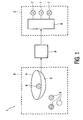
- FIG. 1 gives a schematic overview of the different components of the lighting device 1 according to the present invention.
- the lighting device 1 comprises a lighting unit 2 and a user interface 3.
- the following elements can be distinguished: a detection device 4 such as, for example, an antenna, and the transponders 6.
- the detection device 4 is mounted on a bowl 5.
- the transponders 6 are positioned outside the bowl in this example, they are considered to be inactive, i.e. they are not detected by the detection device 4, whereas inside the bowl they are active, i.e. they are detected and the transponders send back a response signal.
- This response signal is converted into signals suitable for the driver circuit 8 to drive the light sources 7.
- This conversion from response signal to the choice of color and/or intensity of the lighting unit 2 is performed by a processing unit 9 - for instance a personal computer - which may be a separate entity, but it may alternatively be integrated in the user interface 3 or in the lighting unit 2.
- the user interface 3 can be seen as the remote control for the lighting in the room.
- the information derived from the response signal is sent to the processing unit 9, and the converted data is sent to the driver circuit 8. This transfer of information may be through physical interconnection of the separate units, but it may alternatively be done by wireless transmission of the information.
- the light sources 7 may be LEDs of different colors or alternative light sources such as conventional lamps.
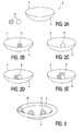
- the user interface 3 of the first embodiment is shown in the Figures 2A-2E .
- This user interface 3 has a bowl-like container 5 and a number of transponders 6.
- the bowl-like container 5 may be a bowl, like a fruit-bowl which may have a decorative value on a table, but also any other shape suitable for containing the transponders 6.
- the bowl-like container 5 is provided with a detection device 4; this may be a coil or an antenna which is mounted on the edge of the bowl-like container 5.
- This detection device 4 has to be provided with a power supply and means for reading the information from the transponders 6.
- RFID tags - RFID stands for Radio Frequency Identification - may be chosen as the transponders 6. These RFID tags comprise an IC which can be programmed such that it contains an ID number.
- the detection device 4 comprises an antenna which sends an electromagnetic signal. This electromagnetic signal is received by the RFID tags, which use the energy from this signal for their power supply, and the RFID tags send back a response signal with the identification as programme
- This information is sent to the processing unit 9, in which it is converted into an input signal for the lighting unit 2.
- This processing unit 9 will translate this response signal into the appropriate parameters to drive a lighting device 2. If the lighting device 2 is a LED system, these parameters may be the currents required to have a certain light output of the LEDs, or in the case of a large number of LEDs, these parameters may determine which LEDs are on and which are off.
- the lighting unit 2 is in the off state, all the transponders are outside the bowl-like container 5, which is referred to as their first or inactive position.
- the transponders 6 are contained in a marble-shaped tangible object - also referred to as marbles below - which are colored so as to correspond to the contribution the marble makes to the desired color of the lighting. For instance, if the lighting unit comprises red, green, and blue LEDs, then the marbles are also red, green, and blue in color.
- the lighting unit will emit light of only one color corresponding to the transponder 6 which is in its active position.
- the intensity of the light can be controlled by adding more marbles of the same colors. It may be chosen to increase the power on the LEDs linearly with the number of marbles of the corresponding color which are active.
- the sensitivity of the human eye shows a logarithmic behavior, i.e. the eye perceives the increase in intensity as linear if the power of the lighting sources is increased exponentially.
- the processing unit 9 may be programmed such that adding marbles to the bowl-like container 5 causes the intensity to increase exponentially.
- the bowl-like container 5 comprises a number of marbles chosen to give the desired color of lighting, and the intensity has to be increased, then marbles have to be added in the same ratio as already present in the bowl-like container 5 in order to keep the color of the light the same.
- the processing unit 9 is programmed to increase the light intensity in dependence on the ratio of the already active marbles of different color. So, these dedicated light-intensity marbles do not change the lighting color.
- the light intensity may also be controlled by means of marbles of different size: the larger the marble, the higher the light intensity.
- the marbles chosen to be inactive may be put in a separate box or just laid beside the bowl-like container.
- a bowl-like container 5 may be used with a groove 10, located outside the region enclosed by the detection device 4, where the inactive marbles can be put.
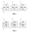
- FIG 4 gives a second embodiment of the present invention.
- the transponder 6 is incorporated in a cube 11 which is placed on a surface 15, for instance a table.
- the detection device 4 may be installed in the edge of the table top or in some region of the table top.
- the transponders 6 are each provided with a switching element 14 for enabling the transponder 6 to change from inactive to active.
- this switching element 14 may be a gravity switch, which is open - the off or inactive position - when the cube is in its first position, and it is closed - the on or active position - when the cube is turned upside-down into its second position.
- the major parts of this type of transponder 6 can be distinguished inside the cube: the IC 12 with the programmed information, for instance the ID number, the antenna 13 for receiving and returning signals, and the switching element 14.
- the cubes 11 may be colored so as to correspond to the color of the lighting to be controlled.
- the side pointing up when the cube is inactive may be provided with just an indication of the appropriate color, e.g. black with a colored dot, while the side pointing up when active is fully colored.
- the left cube 11 is active, whereas the center and right cubes 11 are inactive.
- the way in which the lighting color and intensity are controlled is similar to the first embodiment, the difference is found in the way the transponders are transferred from their first position to their second position: in the first embodiment by putting the marbles in the bowl-like container 4, in the second embodiment by turning the cubes 11 upside-down.
- FIG. 5 An alternative for the gravity switch is given in Figure 5 .
- the cube 11 is provided with a cavity 16.
- a transponder 6 is positioned which can move in this cavity 16.
- the cavity 16 is provided with a metal shielding 17 which covers half of the cavity.
- the shielding 17 covers the upper half of the cavity 16 when the cube 11 is in its second - active - position; in this orientation of the cube 11 the transponder 6 will be detected by the detection device 4.
- the shielding 17 will cover the lower half of the cavity, the transponder 6 will fall down, and the communication from the RFID tag will be cut off, so that the RFID tag will not be seen by the detection device 4, i.e. is inactive.
- the use of cubes is not limiting this example, the tangible objects comprising the transponder 6 may have different shapes, for instance a flat disc or a cylinder.
- the two embodiments may be combined, for instance if the transponder 6 is provided with a switching element 14, it can also be used in a bowl-like container 5. In that case, the transponders 6 remain in the bowl-like container 5 and are transferred from their first position to their second position by turning them upside-down. Preferably, the transponders are then disc- or a pebble-shaped.
- the relative positions of the cubes 11 on the surface 15 determine which detection device 4 sees the presence of said cubes 11 and they can thus be used to indicate in which specific parts of the room the lighting is controlled.
- the present invention relates to a lighting system 1 with a user interface 3 for controlling the lighting color and/or intensity of a lighting unit 2 determining the lighting conditions in a room.
- the user interface 3 is based on a system comprising a detection device 4 and transponders 6. Bringing the transponders 6 within the detection device 4 so that they will be detected causes the transponders 6 to send a response signal, which signal controls the lighting color and/or intensity of the lighting unit 2.
- Each transponder 6 is programmed to control a particular color or a specific light intensity.
Landscapes
- Engineering & Computer Science (AREA)
- General Engineering & Computer Science (AREA)
- Theoretical Computer Science (AREA)
- Human Computer Interaction (AREA)
- Physics & Mathematics (AREA)
- General Physics & Mathematics (AREA)
- Circuit Arrangement For Electric Light Sources In General (AREA)
Abstract
Description
- The invention relates to a lighting device comprising a lighting unit and an interface for controlling the lighting color and/or intensity of the lighting unit.
- The invention further relates to a user interface for controlling a lighting device, to an assembly of a lighting unit and a processing unit controlled by such a user interface, and to a method of controlling a lighting device.
- Present-day light sources mainly contain only one lighting color and these light sources can be controlled by switching them on or off or by dimming. In the near future light sources which are capable of producing a whole spectrum of colored light will become commonplace, also in every household. Such light sources will enable the creation of almost any color and atmosphere, depending on the room or place to be lit.
- As a consequence, the control of such light sources will become more complex, because besides the light intensity or brightness, also the color aspects have to be controlled. Since the change of lighting color will be new to many people, it is of importance that such a control unit is easy to use.
WO 2004/072840, published on 26/08/2004 , already discloses such an intuitive control. - It is a disadvantage of the prior art technology that it does not provide an easy method of controlling light sources with a wide spectrum.
- It is an object of the present invention to provide a lighting device which can be controlled in an easy and intuitive manner.
- According to the present invention, this object is realized by a lighting device comprising a lighting unit and a user interface for controlling the lighting color and/or intensity of the lighting unit, said user interface having a plurality of transponders and a detection device for detecting transponders, each transponder being arranged to control a particular lighting color and/or intensity and to assume a first position corresponding to a state in which said transponder is not detected by the detecting device, and a second position corresponding to a state in which said transponder is detected by the detection device and sends a response signal, said response signal controlling the lighting color and/or intensity of the lighting unit.
- The invention is based on the recognition that by moving tangible objects - here referred to as transponders - with respect to a detection device for these objects it will become very easy for a user to change the color or the intensity of a light source, especially if each transponder corresponds to a particular color. For instance, if a user wants to change the intensity of a certain color, the only thing he needs to do is to change a transponder corresponding to that color from one position to another position. This movement of the transponder will cause the transponder to change its response signal, and this response signal is a measure for the change in lighting color.
- In a preferred embodiment, the particular lighting colors to be controlled comprise the primary colors red, green, and blue.
- In the 1931-CIE-chromaticity diagram, these primary colors will form a triangle and all the colors within this triangle can be generated by adjustment of the ratio of the intensities of the three relevant primary light sources. In particular, this enables the choice of a wide range of color temperatures of white light, from cold light - like the light of halogen-type lamps - to warm light - like the light of conventional light bulbs.
- This is applicable to all kinds of light sources. Examples are incandescent lamps, light emitting diodes (LEDs); but the invention is not restricted to these examples.
- A further embodiment is characterized in that the intensity of a lighting color is proportional to the number of transponders arranged to control said color and assuming the second position.
- The arrangement of this embodiment is very favorable for achieving an intuitive control of a lighting device. The more transponders are put in their second position, the more light output is generated of that specific color. The relation between the number of transponders may, for instance, be chosen linearly, i.e. the power is linearly proportional to the number of transponders. Another option is to create an exponential relationship between the number of transponders in the second position and the power fed to the lighting unit; this conforms better to the perceptive aspects of the human eye.
- In a further preferred embodiment, the transponders are RFID tags, each comprising an identification number, and the detection device comprises an antenna arranged to send, in operation, an electromagnetic signal which will be received by the RFID tag, the response signal comprising the identification number of the RFID tag.
- It is preferred to choose Radio Frequency Identification tags (RFID tags) for the transponders. These tags are generally known and widely used, for instance in security systems for shops in order to prevent theft. Such an RFID tag when brought from its first position - in which it is not detected by the detection device - into its second position - in which it is detected by the detection device - will send its identification number or ID number as a response signal. This ID number can be coupled in a unique way to a change in color or intensity, for instance by means of a look-up table.
- It will also be possible to couple ID numbers of transponders to change the light intensity proportionally with the already adjusted color, so in a color-neutral way. Furthermore, it will be possible to use 'white' RFID-tags, which change the intensity by adding a certain amount of white light to the lighting unit; in most cases this will change the color of the light. In order to make it comfortable to adjust such a lighting device, the transponders may be given the respective colors they control. Thus, for example, such a system may comprise red, green, and blue transponders for adjusting the primary colors and white transponders to influence the color setting by adding white light.
- An example of such a lighting device is characterized in that the detection device is incorporated in a bowl-like container, and the transponders are incorporated in tangible objects, a transponder being in its first position when it is outside the bowl-like container and in its second position when it is inside the bowl-like container.
- In this example the transponders may be marbles which can be put on a bowl, and all the transponders in the bowl determine the color and intensity of the corresponding lighting unit. Such a bowl may be placed on a table, just like a bowl of fruits, and may be a decorative object in the interior of a household.
- Another example is characterized in that the transponders are each provided with a switching element and are incorporated in tangible objects having at least a first side and a second side, the switch being off when the first side is up and the switch being on when the second side is up, a transponder being in its first position when the tangible object is positioned with its first side up in its second position when the tangible object is positioned with its second side up.
- In this example the transponders are transferred from their first position to their second position by just turning them upside-down. This means that, in the case of the bowl-like container, all the transponders can be inside this bowl at all times, and whether the transponders are active or not is determined by the side which points up.
- In the same way, the detection device may be incorporated in, for instance, the edge or surface of a table, thus providing a lighting device for which all the transponders are just objects lying on the table within the area of the detection device, and the lighting unit is controlled by turning the transponders upside-down (or not).
- The lighting device is further characterized in that the lighting device further comprises a processing unit for converting the response signals from the detection device into an input value for the lighting unit.
- Each transponder which is put in its second position sends a response signal that is to be translated into the information needed for driving the lighting unit. This translation can be easily performed by a processing unit such as, for example, a personal computer. By way of example, the translation may be derived from a look-up table giving the relation between a series of response signals from a number of transponders to the corresponding lighting colors and/or intensities of the lighting unit.
- The invention further relates to a user interface for controlling a lighting unit of such a lighting device, to an assembly of a lighting unit and a processing unit controlled by such a user interface, as well as to a method of controlling this lighting unit.
- These and other aspects of the invention will be apparent from and will be elucidated by way of non-limitative examples with reference to the drawings and the embodiments described hereinafter.
- In the drawings:
-
Figure 1 is a schematic drawing of the lighting device according to the invention; -
Figures 2A-2E give a first embodiment according to the invention; -
Figure 3 is a variation on the first embodiment; -
Figure 4 gives a second embodiment according to the invention; -
Figure 5 is a variation on the second embodiment. -
Figure 1 gives a schematic overview of the different components of thelighting device 1 according to the present invention. Thelighting device 1 comprises a lighting unit 2 and auser interface 3. In theuser interface 3 the following elements can be distinguished: adetection device 4 such as, for example, an antenna, and thetransponders 6. In this example thedetection device 4 is mounted on abowl 5. When thetransponders 6 are positioned outside the bowl in this example, they are considered to be inactive, i.e. they are not detected by thedetection device 4, whereas inside the bowl they are active, i.e. they are detected and the transponders send back a response signal. This response signal is converted into signals suitable for thedriver circuit 8 to drive thelight sources 7. This conversion from response signal to the choice of color and/or intensity of the lighting unit 2 is performed by a processing unit 9 - for instance a personal computer - which may be a separate entity, but it may alternatively be integrated in theuser interface 3 or in the lighting unit 2. - The
user interface 3 can be seen as the remote control for the lighting in the room. The information derived from the response signal is sent to the processing unit 9, and the converted data is sent to thedriver circuit 8. This transfer of information may be through physical interconnection of the separate units, but it may alternatively be done by wireless transmission of the information. - The
light sources 7 may be LEDs of different colors or alternative light sources such as conventional lamps. - The present invention will now be described on the basis of two examples, but is not limited to these examples.
- The
user interface 3 of the first embodiment is shown in theFigures 2A-2E . Thisuser interface 3 has a bowl-like container 5 and a number oftransponders 6. The bowl-like container 5 may be a bowl, like a fruit-bowl which may have a decorative value on a table, but also any other shape suitable for containing thetransponders 6. The bowl-like container 5 is provided with adetection device 4; this may be a coil or an antenna which is mounted on the edge of the bowl-like container 5. Thisdetection device 4 has to be provided with a power supply and means for reading the information from thetransponders 6. RFID tags - RFID stands for Radio Frequency Identification - may be chosen as thetransponders 6. These RFID tags comprise an IC which can be programmed such that it contains an ID number. Thedetection device 4 comprises an antenna which sends an electromagnetic signal. This electromagnetic signal is received by the RFID tags, which use the energy from this signal for their power supply, and the RFID tags send back a response signal with the identification as programmed in said RFID tag. - This information is sent to the processing unit 9, in which it is converted into an input signal for the lighting unit 2. This processing unit 9 will translate this response signal into the appropriate parameters to drive a lighting device 2. If the lighting device 2 is a LED system, these parameters may be the currents required to have a certain light output of the LEDs, or in the case of a large number of LEDs, these parameters may determine which LEDs are on and which are off.
- In
Figure 2A the lighting unit 2 is in the off state, all the transponders are outside the bowl-like container 5, which is referred to as their first or inactive position. In this example thetransponders 6 are contained in a marble-shaped tangible object - also referred to as marbles below - which are colored so as to correspond to the contribution the marble makes to the desired color of the lighting. For instance, if the lighting unit comprises red, green, and blue LEDs, then the marbles are also red, green, and blue in color. In theFigures 2B and 2C the lighting unit will emit light of only one color corresponding to thetransponder 6 which is in its active position. - Adding
more transponders 6 to the bowl-like container 5 will give rise to a mixing of colors as shown inFigures 2D and 2E . The intensity of the light can be controlled by adding more marbles of the same colors. It may be chosen to increase the power on the LEDs linearly with the number of marbles of the corresponding color which are active. - The sensitivity of the human eye shows a logarithmic behavior, i.e. the eye perceives the increase in intensity as linear if the power of the lighting sources is increased exponentially. For that reason, the processing unit 9 may be programmed such that adding marbles to the bowl-
like container 5 causes the intensity to increase exponentially. - When the bowl-
like container 5 comprises a number of marbles chosen to give the desired color of lighting, and the intensity has to be increased, then marbles have to be added in the same ratio as already present in the bowl-like container 5 in order to keep the color of the light the same. As a possible alternative for increasing the light intensity, use may be made of dedicated light-intensity marbles. For these marbles the processing unit 9 is programmed to increase the light intensity in dependence on the ratio of the already active marbles of different color. So, these dedicated light-intensity marbles do not change the lighting color. - The light intensity may also be controlled by means of marbles of different size: the larger the marble, the higher the light intensity.
- Furthermore, it will be possible to use marbles with mixed colors, for instance a purple marble will drive a blue and a red LED simultaneously.
- The marbles chosen to be inactive may be put in a separate box or just laid beside the bowl-like container. As an alternative, as shown in
Figure 3 , a bowl-like container 5 may be used with agroove 10, located outside the region enclosed by thedetection device 4, where the inactive marbles can be put. -
Figure 4 gives a second embodiment of the present invention. In this example thetransponder 6 is incorporated in acube 11 which is placed on asurface 15, for instance a table. Thedetection device 4 may be installed in the edge of the table top or in some region of the table top. Additionally, thetransponders 6 are each provided with a switchingelement 14 for enabling thetransponder 6 to change from inactive to active. For instance, this switchingelement 14 may be a gravity switch, which is open - the off or inactive position - when the cube is in its first position, and it is closed - the on or active position - when the cube is turned upside-down into its second position. InFigure 4 , the major parts of this type oftransponder 6 can be distinguished inside the cube: theIC 12 with the programmed information, for instance the ID number, theantenna 13 for receiving and returning signals, and the switchingelement 14. - In this embodiment the
cubes 11 may be colored so as to correspond to the color of the lighting to be controlled. In order to see what is the active and in-active position of the cube, the side pointing up when the cube is inactive may be provided with just an indication of the appropriate color, e.g. black with a colored dot, while the side pointing up when active is fully colored. InFigure 4 , theleft cube 11 is active, whereas the center andright cubes 11 are inactive. The way in which the lighting color and intensity are controlled is similar to the first embodiment, the difference is found in the way the transponders are transferred from their first position to their second position: in the first embodiment by putting the marbles in the bowl-like container 4, in the second embodiment by turning thecubes 11 upside-down. - An alternative for the gravity switch is given in
Figure 5 . Here thecube 11 is provided with acavity 16. In this cavity 16 atransponder 6 is positioned which can move in thiscavity 16. Furthermore, thecavity 16 is provided with a metal shielding 17 which covers half of the cavity. In the left cube inFigure 5 , the shielding 17 covers the upper half of thecavity 16 when thecube 11 is in its second - active - position; in this orientation of thecube 11 thetransponder 6 will be detected by thedetection device 4. When thecube 11 is turned upside-down, as has been done for the center and right cubes ofFigure 5 , the shielding 17 will cover the lower half of the cavity, thetransponder 6 will fall down, and the communication from the RFID tag will be cut off, so that the RFID tag will not be seen by thedetection device 4, i.e. is inactive. - Here also, the use of cubes is not limiting this example, the tangible objects comprising the
transponder 6 may have different shapes, for instance a flat disc or a cylinder. - Furthermore, the two embodiments may be combined, for instance if the
transponder 6 is provided with a switchingelement 14, it can also be used in a bowl-like container 5. In that case, thetransponders 6 remain in the bowl-like container 5 and are transferred from their first position to their second position by turning them upside-down. Preferably, the transponders are then disc- or a pebble-shaped. - Dividing the
surface 15 into a number of sub-areas, each sub-area being provided with adetection device 4, renders it possible to use thesurface 15 as a map of the room in which the lighting has to be controlled. The relative positions of thecubes 11 on thesurface 15 determine whichdetection device 4 sees the presence of saidcubes 11 and they can thus be used to indicate in which specific parts of the room the lighting is controlled. - Summarizing, the present invention relates to a
lighting system 1 with auser interface 3 for controlling the lighting color and/or intensity of a lighting unit 2 determining the lighting conditions in a room. Theuser interface 3 is based on a system comprising adetection device 4 andtransponders 6. Bringing thetransponders 6 within thedetection device 4 so that they will be detected causes thetransponders 6 to send a response signal, which signal controls the lighting color and/or intensity of the lighting unit 2. Eachtransponder 6 is programmed to control a particular color or a specific light intensity.
Claims (17)
- A lighting device (1) comprising a lighting unit (2) and a user interface (3) for controlling the lighting color and/or intensity of the lighting unit (2), said user interface having a plurality of transponders (6), a container (5) provided with a detecting device (4) for detecting said transponders (6), each transponder (6) being arranged to control a particular lighting color and/or intensity and to assume a first position outside the container (5) corresponding to a state in which said transponder (6) is inactive and is not detected by the detecting device (4), and a second position inside the container (5) corresponding to a state in which said transponder (6) is active and is detected by the detecting means (4) and sends a response signal, said response signal controls the lighting color and/or intensity of the lighting unit (2).
- A lighting device (1) according to claim 1, characterized in that the particular lighting colors to be controlled comprise the primary colors red, green, and blue.
- A lighting device (1) according to claim 1 or 2, characterized in that the lighting unit (2) comprises LEDs (7).
- A lighting device (1) according to claim 1, 2, or 3, characterized in that the intensity of a lighting color is proportional to the number of transponders (6) arranged to control said color and assuming the second position.
- A lighting device (1) according to claim 1, 2, 3, or 4, characterized in that the transponders (6) are RFID tags, each comprising an identification number.
- A lighting device (1) according to claim 5, characterized in that the detection device (4) comprises an antenna arranged to send, in operation, an electromagnetic signal which will be received by the RFID tag, the response signal comprising the identification number of the RFID tag.
- A lighting device (1) according to claim 1, 2, 3, 4, 5, or 6, characterized in that the detection device (4) is incorporated in a bowl-like container (5) and the transponders (6) are incorporated in tangible objects, a transponder being in its first position when it is outside the bowl-like container (5) and in its second position when it is inside the bowl-like container (5).
- A lighting device (1) according to claim 7, characterized in that each tangible object has a color corresponding to the lighting color it is arranged to control.
- A lighting device (1) according to claim 7 or 8, characterized in that the tangible objects have the shape of marbles.
- A lighting device (1) according to claim 1, 2, 3, 4, 5, or 6, characterized in that the transponders (6) are each provided with a switching element (14) and are incorporated in tangible objects having at least a first side and a second side, the switch being off when the first side is up and the switch being on when the second side is up, a transponder (6) being in its first position when the tangible object is positioned with its first side up and it is in its second position when the tangible object is positioned with its second side up.
- A lighting device (1) according to claim 10, characterized in that the second side of each tangible object is colored so as to correspond to the lighting color it controls, and the first side of each tangible object bears an indication of said color.
- A lighting device (1) according to claim 10 or 11, characterized in that the detection device (4) is incorporated in a bowl-like container (5) and the transponders (6) having the shape of disc-like tangible objects are positioned in said bowl-like container (4).
- A lighting device (1) according to claim 10 or 11, characterized in that the detection device (4) encloses a surface (15), in particular a table, and the transponders (6) having the shape of cube-like tangible objects (11) are positioned on said surface (15).
- A lighting device (1) according to any of the preceding claims, characterized in that the lighting device (1) further comprises a processing unit (9) for converting the response signals from the detection device (4) into input values for the lighting unit (2).
- A user interface (3) for controlling a lighting unit (2), having a plurality of transponders (6), a container (5) provided with a detecting device (4), each transponder (6) being arranged to control a particular lighting color and/or intensity of the lighting unit (2) and to assume a first position outside the container (5) corresponding to a state in which said transponder (6) is inactive and is not detected by the detecting means (4), and a second position inside the container (5) corresponding to a state in which said transponder (6) is active and is detected by the detecting device (4) and sends a response signal, said response signal controls the lighting color and/or intensity of the lighting unit (2).
- An assembly of a lighting unit (2) and a processing unit (9), characterized in that said processing unit (9) is arranged to receive a response signal delivered by the user interface (3) of claim 15 and to convert this response signal into an input value for the lighting unit (2).
- A method for controlling the lighting color and/or intensity of a lighting device (1) by using a user interface (3) having a plurality of transponders (6) and a container (5) provided with a detecting device (4), each transponder (6) being arranged to control a particular lighting color and/or intensity of the lighting unit (4), by changing a transponder (6) from a first position outside the container (5) corresponding to a state in which said transponder (6) is inactive and is not detected by the detecting means (4), to a second position inside the container (5) corresponding to a state in which said transponder (6) is active and is detected by the detecting device (4) and sends a response signal, said response signal controls the lighting color and/or intensity of the lighting unit (2).
Priority Applications (1)
| Application Number | Priority Date | Filing Date | Title |
|---|---|---|---|
| EP05731773A EP1752024B1 (en) | 2004-05-05 | 2005-04-27 | Lighting device with user interface for light control |
Applications Claiming Priority (3)
| Application Number | Priority Date | Filing Date | Title |
|---|---|---|---|
| EP04101935 | 2004-05-05 | ||
| EP05731773A EP1752024B1 (en) | 2004-05-05 | 2005-04-27 | Lighting device with user interface for light control |
| PCT/IB2005/051376 WO2005107337A1 (en) | 2004-05-05 | 2005-04-27 | Lighting device with user interface for light control |
Publications (2)
| Publication Number | Publication Date |
|---|---|
| EP1752024A1 EP1752024A1 (en) | 2007-02-14 |
| EP1752024B1 true EP1752024B1 (en) | 2009-11-18 |
Family
ID=34966280
Family Applications (1)
| Application Number | Title | Priority Date | Filing Date |
|---|---|---|---|
| EP05731773A Expired - Lifetime EP1752024B1 (en) | 2004-05-05 | 2005-04-27 | Lighting device with user interface for light control |
Country Status (9)
| Country | Link |
|---|---|
| US (1) | US7675238B2 (en) |
| EP (1) | EP1752024B1 (en) |
| JP (1) | JP4722126B2 (en) |
| KR (1) | KR101163075B1 (en) |
| CN (1) | CN1951157B (en) |
| AT (1) | ATE449527T1 (en) |
| DE (1) | DE602005017769D1 (en) |
| TW (1) | TW200610442A (en) |
| WO (1) | WO2005107337A1 (en) |
Cited By (1)
| Publication number | Priority date | Publication date | Assignee | Title |
|---|---|---|---|---|
| EP2975913A2 (en) | 2014-07-16 | 2016-01-20 | Holy Trinity GmbH | Method for controlling a luminaire by means of a mobile terminal device |
Families Citing this family (50)
| Publication number | Priority date | Publication date | Assignee | Title |
|---|---|---|---|---|
| US20050259424A1 (en) * | 2004-05-18 | 2005-11-24 | Zampini Thomas L Ii | Collimating and controlling light produced by light emitting diodes |
| WO2006129250A1 (en) | 2005-06-01 | 2006-12-07 | Koninklijke Philips Electronics N.V. | Atmosphere device with user interface for light and fragrance control |
| WO2007110791A1 (en) * | 2006-03-24 | 2007-10-04 | Philips Intellectual Property & Standards Gmbh | Target atmosphere technique for easy light management systems and atmosphere localisation / rfid-assisted sensor network |
| US7766511B2 (en) * | 2006-04-24 | 2010-08-03 | Integrated Illumination Systems | LED light fixture |
| CN101461287A (en) | 2006-06-02 | 2009-06-17 | 皇家飞利浦电子股份有限公司 | Control circuit for lamp and method of driving lamp |
| US8339247B2 (en) | 2006-09-06 | 2012-12-25 | Koninklijke Philips Electronics N.V. | Lighting control |
| CN101518153A (en) * | 2006-09-12 | 2009-08-26 | 皇家飞利浦电子股份有限公司 | System for selecting and controlling light settings |
| WO2008059412A1 (en) * | 2006-11-17 | 2008-05-22 | Philips Intellectual Property & Standards Gmbh | Lighting device for floors |
| US7729941B2 (en) | 2006-11-17 | 2010-06-01 | Integrated Illumination Systems, Inc. | Apparatus and method of using lighting systems to enhance brand recognition |
| US8013538B2 (en) | 2007-01-26 | 2011-09-06 | Integrated Illumination Systems, Inc. | TRI-light |
| WO2008146245A1 (en) * | 2007-06-01 | 2008-12-04 | Koninklijke Philips Electronics N. V. | A user interface and a method for the easy creation of atmospheres with an atmosphere creation system |
| WO2009004539A1 (en) * | 2007-06-29 | 2009-01-08 | Philips Intellectual Property & Standards Gmbh | Light control system with automatic position detection of objects and method for controlling a lighting system by automatically detecting the position of objects |
| US8742686B2 (en) * | 2007-09-24 | 2014-06-03 | Integrated Illumination Systems, Inc. | Systems and methods for providing an OEM level networked lighting system |
| TW200950590A (en) | 2008-01-30 | 2009-12-01 | Koninkl Philips Electronics Nv | Lighting system and method for operating a lighting system |
| US8255487B2 (en) * | 2008-05-16 | 2012-08-28 | Integrated Illumination Systems, Inc. | Systems and methods for communicating in a lighting network |
| WO2010073175A2 (en) * | 2008-12-25 | 2010-07-01 | Koninklijke Philips Electronics N.V. | A control system |
| US8585245B2 (en) | 2009-04-23 | 2013-11-19 | Integrated Illumination Systems, Inc. | Systems and methods for sealing a lighting fixture |
| EP2437954B1 (en) * | 2009-06-02 | 2014-06-11 | Koninklijke Philips N.V. | Control arrangement for controlling an atmosphere generating device |
| KR20110127968A (en) * | 2010-05-20 | 2011-11-28 | 엘에스산전 주식회사 | Remote control transceiver and method using R FID |
| CN102164433B (en) * | 2011-01-18 | 2013-12-18 | 深圳市聚作照明股份有限公司 | Light emitting diode (LED) lamp with radio frequency identification function |
| EP2668823B1 (en) | 2011-01-25 | 2016-04-27 | Koninklijke Philips N.V. | Control device |
| DE102011012336A1 (en) * | 2011-02-24 | 2012-08-30 | Dula-Werke Dustmann & Co. Gmbh | Method for the automated setting of environmental parameters on presentation surfaces and device for this purpose |
| US10321541B2 (en) | 2011-03-11 | 2019-06-11 | Ilumi Solutions, Inc. | LED lighting device |
| US8890435B2 (en) | 2011-03-11 | 2014-11-18 | Ilumi Solutions, Inc. | Wireless lighting control system |
| US10630820B2 (en) | 2011-03-11 | 2020-04-21 | Ilumi Solutions, Inc. | Wireless communication methods |
| US9066381B2 (en) | 2011-03-16 | 2015-06-23 | Integrated Illumination Systems, Inc. | System and method for low level dimming |
| US9521725B2 (en) | 2011-07-26 | 2016-12-13 | Hunter Industries, Inc. | Systems and methods for providing power and data to lighting devices |
| US11917740B2 (en) | 2011-07-26 | 2024-02-27 | Hunter Industries, Inc. | Systems and methods for providing power and data to devices |
| US10874003B2 (en) | 2011-07-26 | 2020-12-22 | Hunter Industries, Inc. | Systems and methods for providing power and data to devices |
| US8710770B2 (en) | 2011-07-26 | 2014-04-29 | Hunter Industries, Inc. | Systems and methods for providing power and data to lighting devices |
| US9609720B2 (en) | 2011-07-26 | 2017-03-28 | Hunter Industries, Inc. | Systems and methods for providing power and data to lighting devices |
| US20150237700A1 (en) | 2011-07-26 | 2015-08-20 | Hunter Industries, Inc. | Systems and methods to control color and brightness of lighting devices |
| US8894437B2 (en) | 2012-07-19 | 2014-11-25 | Integrated Illumination Systems, Inc. | Systems and methods for connector enabling vertical removal |
| US9379578B2 (en) | 2012-11-19 | 2016-06-28 | Integrated Illumination Systems, Inc. | Systems and methods for multi-state power management |
| US9420665B2 (en) | 2012-12-28 | 2016-08-16 | Integration Illumination Systems, Inc. | Systems and methods for continuous adjustment of reference signal to control chip |
| US9485814B2 (en) | 2013-01-04 | 2016-11-01 | Integrated Illumination Systems, Inc. | Systems and methods for a hysteresis based driver using a LED as a voltage reference |
| US9804024B2 (en) * | 2013-03-14 | 2017-10-31 | Mojo Labs, Inc. | Light measurement and/or control translation for daylighting |
| PT3554198T (en) * | 2013-08-19 | 2021-05-25 | Signify Holding Bv | Programmable lighting device and method and system for programming lighting device |
| US10070496B2 (en) | 2015-03-30 | 2018-09-04 | Mojo Labs, Inc. | Task to wall color control |
| US10918030B2 (en) | 2015-05-26 | 2021-02-16 | Hunter Industries, Inc. | Decoder systems and methods for irrigation control |
| US10228711B2 (en) | 2015-05-26 | 2019-03-12 | Hunter Industries, Inc. | Decoder systems and methods for irrigation control |
| US10030844B2 (en) | 2015-05-29 | 2018-07-24 | Integrated Illumination Systems, Inc. | Systems, methods and apparatus for illumination using asymmetrical optics |
| US10060599B2 (en) | 2015-05-29 | 2018-08-28 | Integrated Illumination Systems, Inc. | Systems, methods and apparatus for programmable light fixtures |
| US11978336B2 (en) | 2015-07-07 | 2024-05-07 | Ilumi Solutions, Inc. | Wireless control device and methods thereof |
| US10339796B2 (en) | 2015-07-07 | 2019-07-02 | Ilumi Sulutions, Inc. | Wireless control device and methods thereof |
| WO2017007926A1 (en) | 2015-07-07 | 2017-01-12 | Ilumi Solutions, Inc. | Wireless communication methods |
| US10801714B1 (en) | 2019-10-03 | 2020-10-13 | CarJamz, Inc. | Lighting device |
| WO2022043220A1 (en) * | 2020-08-31 | 2022-03-03 | Signify Holding B.V. | A controller for mapping a light scene onto a plurality of lighting units and a method thereof |
| US12416908B2 (en) | 2022-12-29 | 2025-09-16 | Integrated Illumination Systems, Inc. | Systems and methods for manufacturing light fixtures |
| US12297996B2 (en) | 2023-02-16 | 2025-05-13 | Integrated Illumination Systems, Inc. | Cove light fixture with hidden integrated air return |
Family Cites Families (15)
| Publication number | Priority date | Publication date | Assignee | Title |
|---|---|---|---|---|
| JPH0448585A (en) * | 1990-06-15 | 1992-02-18 | Matsushita Electric Works Ltd | Toning control device |
| US6869204B2 (en) * | 1997-08-26 | 2005-03-22 | Color Kinetics Incorporated | Light fixtures for illumination of liquids |
| US6967448B2 (en) * | 1997-08-26 | 2005-11-22 | Color Kinetics, Incorporated | Methods and apparatus for controlling illumination |
| US7132804B2 (en) * | 1997-12-17 | 2006-11-07 | Color Kinetics Incorporated | Data delivery track |
| US6340864B1 (en) * | 1999-08-10 | 2002-01-22 | Philips Electronics North America Corporation | Lighting control system including a wireless remote sensor |
| US6608617B2 (en) * | 2000-05-09 | 2003-08-19 | Marc O. Hoffknecht | Lighting control interface |
| US7202613B2 (en) * | 2001-05-30 | 2007-04-10 | Color Kinetics Incorporated | Controlled lighting methods and apparatus |
| US7303300B2 (en) * | 2000-09-27 | 2007-12-04 | Color Kinetics Incorporated | Methods and systems for illuminating household products |
| GB0028093D0 (en) * | 2000-11-17 | 2001-01-03 | Ratcliffe Anthony B | Electrical power control system |
| JP2002319497A (en) * | 2001-04-20 | 2002-10-31 | Toyoda Gosei Co Ltd | Color change lighting device |
| DE10119648B4 (en) * | 2001-04-20 | 2013-04-25 | Thomson Licensing | Arrangement for the operation of television technical devices |
| US7358929B2 (en) * | 2001-09-17 | 2008-04-15 | Philips Solid-State Lighting Solutions, Inc. | Tile lighting methods and systems |
| US20040141321A1 (en) * | 2002-11-20 | 2004-07-22 | Color Kinetics, Incorporated | Lighting and other perceivable effects for toys and other consumer products |
| WO2004072840A1 (en) * | 2003-02-14 | 2004-08-26 | Koninklijke Philips Electronics N.V. | Method for controlling lighting parameters, controlling device, lighting system |
| US7061366B2 (en) * | 2004-04-12 | 2006-06-13 | Microsoft Corporation | Finding location and ranging explorer |
-
2005
- 2005-04-27 US US11/568,626 patent/US7675238B2/en active Active
- 2005-04-27 DE DE602005017769T patent/DE602005017769D1/en not_active Expired - Lifetime
- 2005-04-27 CN CN2005800145156A patent/CN1951157B/en not_active Expired - Lifetime
- 2005-04-27 KR KR1020067025486A patent/KR101163075B1/en not_active Expired - Lifetime
- 2005-04-27 JP JP2007512612A patent/JP4722126B2/en not_active Expired - Lifetime
- 2005-04-27 EP EP05731773A patent/EP1752024B1/en not_active Expired - Lifetime
- 2005-04-27 WO PCT/IB2005/051376 patent/WO2005107337A1/en not_active Ceased
- 2005-04-27 AT AT05731773T patent/ATE449527T1/en not_active IP Right Cessation
- 2005-04-29 TW TW094113980A patent/TW200610442A/en unknown
Cited By (2)
| Publication number | Priority date | Publication date | Assignee | Title |
|---|---|---|---|---|
| EP2975913A2 (en) | 2014-07-16 | 2016-01-20 | Holy Trinity GmbH | Method for controlling a luminaire by means of a mobile terminal device |
| DE102014109989A1 (en) | 2014-07-16 | 2016-01-21 | Holy Trinity GmbH | Method for controlling a luminaire by means of a mobile terminal |
Also Published As
| Publication number | Publication date |
|---|---|
| CN1951157B (en) | 2011-02-02 |
| US20080284348A1 (en) | 2008-11-20 |
| JP2007536720A (en) | 2007-12-13 |
| KR101163075B1 (en) | 2012-07-06 |
| TW200610442A (en) | 2006-03-16 |
| CN1951157A (en) | 2007-04-18 |
| ATE449527T1 (en) | 2009-12-15 |
| KR20070028397A (en) | 2007-03-12 |
| US7675238B2 (en) | 2010-03-09 |
| EP1752024A1 (en) | 2007-02-14 |
| WO2005107337A1 (en) | 2005-11-10 |
| DE602005017769D1 (en) | 2009-12-31 |
| JP4722126B2 (en) | 2011-07-13 |
Similar Documents
| Publication | Publication Date | Title |
|---|---|---|
| EP1752024B1 (en) | Lighting device with user interface for light control | |
| EP1800204B1 (en) | Lighting device with user interface for light control | |
| EP1890733B1 (en) | Atmosphere device with user interface for light and fragrance control | |
| US8063568B2 (en) | Remote color control device and lighting system | |
| EP0790457B1 (en) | Polychrome lighting device, particularly for the decorative lighting of rooms and the like | |
| US12342432B2 (en) | Color temperature control of a lighting device | |
| CN101341462A (en) | Button Arrangement for Color Lighting Controller | |
| TWI749541B (en) | Selecting parameters in a color-tuning application | |
| KR20110022665A (en) | User interface devices to control consumer loads and lighting systems using these user interface devices | |
| HK40085971A (en) | Color temperature control of a lighting device |
Legal Events
| Date | Code | Title | Description |
|---|---|---|---|
| PUAI | Public reference made under article 153(3) epc to a published international application that has entered the european phase |
Free format text: ORIGINAL CODE: 0009012 |
|
| 17P | Request for examination filed |
Effective date: 20061205 |
|
| AK | Designated contracting states |
Kind code of ref document: A1 Designated state(s): AT BE BG CH CY CZ DE DK EE ES FI FR GB GR HU IE IS IT LI LT LU MC NL PL PT RO SE SI SK TR |
|
| 17Q | First examination report despatched |
Effective date: 20070704 |
|
| DAX | Request for extension of the european patent (deleted) | ||
| GRAP | Despatch of communication of intention to grant a patent |
Free format text: ORIGINAL CODE: EPIDOSNIGR1 |
|
| GRAS | Grant fee paid |
Free format text: ORIGINAL CODE: EPIDOSNIGR3 |
|
| GRAA | (expected) grant |
Free format text: ORIGINAL CODE: 0009210 |
|
| AK | Designated contracting states |
Kind code of ref document: B1 Designated state(s): AT BE BG CH CY CZ DE DK EE ES FI FR GB GR HU IE IS IT LI LT LU MC NL PL PT RO SE SI SK TR |
|
| REG | Reference to a national code |
Ref country code: GB Ref legal event code: FG4D |
|
| REG | Reference to a national code |
Ref country code: CH Ref legal event code: EP |
|
| REG | Reference to a national code |
Ref country code: IE Ref legal event code: FG4D |
|
| REF | Corresponds to: |
Ref document number: 602005017769 Country of ref document: DE Date of ref document: 20091231 Kind code of ref document: P |
|
| REG | Reference to a national code |
Ref country code: NL Ref legal event code: VDEP Effective date: 20091118 |
|
| LTIE | Lt: invalidation of european patent or patent extension |
Effective date: 20091118 |
|
| PG25 | Lapsed in a contracting state [announced via postgrant information from national office to epo] |
Ref country code: FI Free format text: LAPSE BECAUSE OF FAILURE TO SUBMIT A TRANSLATION OF THE DESCRIPTION OR TO PAY THE FEE WITHIN THE PRESCRIBED TIME-LIMIT Effective date: 20091118 Ref country code: ES Free format text: LAPSE BECAUSE OF FAILURE TO SUBMIT A TRANSLATION OF THE DESCRIPTION OR TO PAY THE FEE WITHIN THE PRESCRIBED TIME-LIMIT Effective date: 20100228 Ref country code: PT Free format text: LAPSE BECAUSE OF FAILURE TO SUBMIT A TRANSLATION OF THE DESCRIPTION OR TO PAY THE FEE WITHIN THE PRESCRIBED TIME-LIMIT Effective date: 20100318 Ref country code: LT Free format text: LAPSE BECAUSE OF FAILURE TO SUBMIT A TRANSLATION OF THE DESCRIPTION OR TO PAY THE FEE WITHIN THE PRESCRIBED TIME-LIMIT Effective date: 20091118 Ref country code: IS Free format text: LAPSE BECAUSE OF FAILURE TO SUBMIT A TRANSLATION OF THE DESCRIPTION OR TO PAY THE FEE WITHIN THE PRESCRIBED TIME-LIMIT Effective date: 20100318 Ref country code: SE Free format text: LAPSE BECAUSE OF FAILURE TO SUBMIT A TRANSLATION OF THE DESCRIPTION OR TO PAY THE FEE WITHIN THE PRESCRIBED TIME-LIMIT Effective date: 20091118 |
|
| PG25 | Lapsed in a contracting state [announced via postgrant information from national office to epo] |
Ref country code: SI Free format text: LAPSE BECAUSE OF FAILURE TO SUBMIT A TRANSLATION OF THE DESCRIPTION OR TO PAY THE FEE WITHIN THE PRESCRIBED TIME-LIMIT Effective date: 20091118 Ref country code: PL Free format text: LAPSE BECAUSE OF FAILURE TO SUBMIT A TRANSLATION OF THE DESCRIPTION OR TO PAY THE FEE WITHIN THE PRESCRIBED TIME-LIMIT Effective date: 20091118 Ref country code: CY Free format text: LAPSE BECAUSE OF FAILURE TO SUBMIT A TRANSLATION OF THE DESCRIPTION OR TO PAY THE FEE WITHIN THE PRESCRIBED TIME-LIMIT Effective date: 20091118 |
|
| PG25 | Lapsed in a contracting state [announced via postgrant information from national office to epo] |
Ref country code: BE Free format text: LAPSE BECAUSE OF FAILURE TO SUBMIT A TRANSLATION OF THE DESCRIPTION OR TO PAY THE FEE WITHIN THE PRESCRIBED TIME-LIMIT Effective date: 20091118 Ref country code: AT Free format text: LAPSE BECAUSE OF FAILURE TO SUBMIT A TRANSLATION OF THE DESCRIPTION OR TO PAY THE FEE WITHIN THE PRESCRIBED TIME-LIMIT Effective date: 20091118 |
|
| PG25 | Lapsed in a contracting state [announced via postgrant information from national office to epo] |
Ref country code: BG Free format text: LAPSE BECAUSE OF FAILURE TO SUBMIT A TRANSLATION OF THE DESCRIPTION OR TO PAY THE FEE WITHIN THE PRESCRIBED TIME-LIMIT Effective date: 20100218 Ref country code: RO Free format text: LAPSE BECAUSE OF FAILURE TO SUBMIT A TRANSLATION OF THE DESCRIPTION OR TO PAY THE FEE WITHIN THE PRESCRIBED TIME-LIMIT Effective date: 20091118 Ref country code: EE Free format text: LAPSE BECAUSE OF FAILURE TO SUBMIT A TRANSLATION OF THE DESCRIPTION OR TO PAY THE FEE WITHIN THE PRESCRIBED TIME-LIMIT Effective date: 20091118 Ref country code: DK Free format text: LAPSE BECAUSE OF FAILURE TO SUBMIT A TRANSLATION OF THE DESCRIPTION OR TO PAY THE FEE WITHIN THE PRESCRIBED TIME-LIMIT Effective date: 20091118 Ref country code: NL Free format text: LAPSE BECAUSE OF FAILURE TO SUBMIT A TRANSLATION OF THE DESCRIPTION OR TO PAY THE FEE WITHIN THE PRESCRIBED TIME-LIMIT Effective date: 20091118 |
|
| PG25 | Lapsed in a contracting state [announced via postgrant information from national office to epo] |
Ref country code: CZ Free format text: LAPSE BECAUSE OF FAILURE TO SUBMIT A TRANSLATION OF THE DESCRIPTION OR TO PAY THE FEE WITHIN THE PRESCRIBED TIME-LIMIT Effective date: 20091118 Ref country code: SK Free format text: LAPSE BECAUSE OF FAILURE TO SUBMIT A TRANSLATION OF THE DESCRIPTION OR TO PAY THE FEE WITHIN THE PRESCRIBED TIME-LIMIT Effective date: 20091118 |
|
| PLBE | No opposition filed within time limit |
Free format text: ORIGINAL CODE: 0009261 |
|
| STAA | Information on the status of an ep patent application or granted ep patent |
Free format text: STATUS: NO OPPOSITION FILED WITHIN TIME LIMIT |
|
| 26N | No opposition filed |
Effective date: 20100819 |
|
| PG25 | Lapsed in a contracting state [announced via postgrant information from national office to epo] |
Ref country code: GR Free format text: LAPSE BECAUSE OF FAILURE TO SUBMIT A TRANSLATION OF THE DESCRIPTION OR TO PAY THE FEE WITHIN THE PRESCRIBED TIME-LIMIT Effective date: 20100219 |
|
| PG25 | Lapsed in a contracting state [announced via postgrant information from national office to epo] |
Ref country code: MC Free format text: LAPSE BECAUSE OF NON-PAYMENT OF DUE FEES Effective date: 20100430 |
|
| REG | Reference to a national code |
Ref country code: CH Ref legal event code: PL |
|
| PG25 | Lapsed in a contracting state [announced via postgrant information from national office to epo] |
Ref country code: IE Free format text: LAPSE BECAUSE OF NON-PAYMENT OF DUE FEES Effective date: 20100427 |
|
| PG25 | Lapsed in a contracting state [announced via postgrant information from national office to epo] |
Ref country code: LI Free format text: LAPSE BECAUSE OF NON-PAYMENT OF DUE FEES Effective date: 20100430 Ref country code: CH Free format text: LAPSE BECAUSE OF NON-PAYMENT OF DUE FEES Effective date: 20100430 |
|
| PG25 | Lapsed in a contracting state [announced via postgrant information from national office to epo] |
Ref country code: IT Free format text: LAPSE BECAUSE OF FAILURE TO SUBMIT A TRANSLATION OF THE DESCRIPTION OR TO PAY THE FEE WITHIN THE PRESCRIBED TIME-LIMIT Effective date: 20091118 |
|
| PG25 | Lapsed in a contracting state [announced via postgrant information from national office to epo] |
Ref country code: HU Free format text: LAPSE BECAUSE OF FAILURE TO SUBMIT A TRANSLATION OF THE DESCRIPTION OR TO PAY THE FEE WITHIN THE PRESCRIBED TIME-LIMIT Effective date: 20100519 Ref country code: LU Free format text: LAPSE BECAUSE OF NON-PAYMENT OF DUE FEES Effective date: 20100427 |
|
| PG25 | Lapsed in a contracting state [announced via postgrant information from national office to epo] |
Ref country code: TR Free format text: LAPSE BECAUSE OF FAILURE TO SUBMIT A TRANSLATION OF THE DESCRIPTION OR TO PAY THE FEE WITHIN THE PRESCRIBED TIME-LIMIT Effective date: 20091118 |
|
| REG | Reference to a national code |
Ref country code: DE Ref legal event code: R082 Ref document number: 602005017769 Country of ref document: DE Representative=s name: MEISSNER, BOLTE & PARTNER GBR, DE |
|
| REG | Reference to a national code |
Ref country code: DE Ref legal event code: R082 Ref document number: 602005017769 Country of ref document: DE Representative=s name: MEISSNER BOLTE PATENTANWAELTE RECHTSANWAELTE P, DE Effective date: 20140328 Ref country code: DE Ref legal event code: R081 Ref document number: 602005017769 Country of ref document: DE Owner name: PHILIPS LIGHTING HOLDING B.V., NL Free format text: FORMER OWNER: KONINKLIJKE PHILIPS ELECTRONICS N.V., EINDHOVEN, NL Effective date: 20140328 Ref country code: DE Ref legal event code: R081 Ref document number: 602005017769 Country of ref document: DE Owner name: KONINKLIJKE PHILIPS N.V., NL Free format text: FORMER OWNER: KONINKLIJKE PHILIPS ELECTRONICS N.V., EINDHOVEN, NL Effective date: 20140328 Ref country code: DE Ref legal event code: R082 Ref document number: 602005017769 Country of ref document: DE Representative=s name: MEISSNER, BOLTE & PARTNER GBR, DE Effective date: 20140328 |
|
| REG | Reference to a national code |
Ref country code: FR Ref legal event code: CD Owner name: KONINKLIJKE PHILIPS ELECTRONICS N.V., NL Effective date: 20141126 Ref country code: FR Ref legal event code: CA Effective date: 20141126 |
|
| REG | Reference to a national code |
Ref country code: FR Ref legal event code: PLFP Year of fee payment: 12 |
|
| REG | Reference to a national code |
Ref country code: GB Ref legal event code: 732E Free format text: REGISTERED BETWEEN 20161006 AND 20161012 |
|
| REG | Reference to a national code |
Ref country code: DE Ref legal event code: R081 Ref document number: 602005017769 Country of ref document: DE Owner name: SIGNIFY HOLDING B.V., NL Free format text: FORMER OWNER: KONINKLIJKE PHILIPS N.V., EINDHOVEN, NL Ref country code: DE Ref legal event code: R082 Ref document number: 602005017769 Country of ref document: DE Representative=s name: MEISSNER BOLTE PATENTANWAELTE RECHTSANWAELTE P, DE Ref country code: DE Ref legal event code: R081 Ref document number: 602005017769 Country of ref document: DE Owner name: PHILIPS LIGHTING HOLDING B.V., NL Free format text: FORMER OWNER: KONINKLIJKE PHILIPS N.V., EINDHOVEN, NL |
|
| REG | Reference to a national code |
Ref country code: FR Ref legal event code: PLFP Year of fee payment: 13 |
|
| REG | Reference to a national code |
Ref country code: FR Ref legal event code: PLFP Year of fee payment: 14 |
|
| REG | Reference to a national code |
Ref country code: DE Ref legal event code: R082 Ref document number: 602005017769 Country of ref document: DE Representative=s name: MEISSNER BOLTE PATENTANWAELTE RECHTSANWAELTE P, DE Ref country code: DE Ref legal event code: R081 Ref document number: 602005017769 Country of ref document: DE Owner name: SIGNIFY HOLDING B.V., NL Free format text: FORMER OWNER: PHILIPS LIGHTING HOLDING B.V., EINDHOVEN, NL |
|
| P01 | Opt-out of the competence of the unified patent court (upc) registered |
Effective date: 20230421 |
|
| PGFP | Annual fee paid to national office [announced via postgrant information from national office to epo] |
Ref country code: GB Payment date: 20240423 Year of fee payment: 20 |
|
| PGFP | Annual fee paid to national office [announced via postgrant information from national office to epo] |
Ref country code: DE Payment date: 20240627 Year of fee payment: 20 |
|
| PGFP | Annual fee paid to national office [announced via postgrant information from national office to epo] |
Ref country code: FR Payment date: 20240430 Year of fee payment: 20 |
|
| REG | Reference to a national code |
Ref country code: DE Ref legal event code: R071 Ref document number: 602005017769 Country of ref document: DE |
|
| REG | Reference to a national code |
Ref country code: GB Ref legal event code: PE20 Expiry date: 20250426 |
|
| PG25 | Lapsed in a contracting state [announced via postgrant information from national office to epo] |
Ref country code: GB Free format text: LAPSE BECAUSE OF EXPIRATION OF PROTECTION Effective date: 20250426 |