EP1752354A2 - Weichenantriebssystem - Google Patents
Weichenantriebssystem Download PDFInfo
- Publication number
- EP1752354A2 EP1752354A2 EP06076792A EP06076792A EP1752354A2 EP 1752354 A2 EP1752354 A2 EP 1752354A2 EP 06076792 A EP06076792 A EP 06076792A EP 06076792 A EP06076792 A EP 06076792A EP 1752354 A2 EP1752354 A2 EP 1752354A2
- Authority
- EP
- European Patent Office
- Prior art keywords
- drive
- drive member
- axis
- crank
- unit
- Prior art date
- Legal status (The legal status is an assumption and is not a legal conclusion. Google has not performed a legal analysis and makes no representation as to the accuracy of the status listed.)
- Granted
Links
Images


Classifications
-
- B—PERFORMING OPERATIONS; TRANSPORTING
- B61—RAILWAYS
- B61L—GUIDING RAILWAY TRAFFIC; ENSURING THE SAFETY OF RAILWAY TRAFFIC
- B61L5/00—Local operating mechanisms for points or track-mounted scotch-blocks; Visible or audible signals; Local operating mechanisms for visible or audible signals
- B61L5/02—Mechanical devices for operating points or scotch-blocks, e.g. local manual control
Definitions
- the present invention relates to the driving of railway points.
- a supplementary drive system for operating long railway points in a coherent and synchronised manner which can be manually operated from one position and that locks the switch rail of a set of points to its adjacent running rail at all supplementary input positions, which is not dependent upon the movement of the switch blade to provide supplementary inputs, and which is tolerant to changes in temperature, rail creep and train run-through is the subject of EP-A-1512603 .
- a drive unit 10 comprises a drive means, e.g. a motor, which drives a drive member 30 along a first axis, substantially parallel to the railway tracks 1-4.
- the drive member engages a crank 32 connected to a drive bar 11, such that movement of the drive member along the first axis is converted by the crank into movement of the drive bar along a second axis orthogonal to the first axis.
- the drive bar is connected to the movable rails 2, 3 of a point system, causing the state of the points to change by suitable operation of the drive means.
- additional cranks 39, 40 may be connected in-line with the drive member so that the rails can be moved at various locations along their length.
- a disadvantage of this system is that the drive unit has to be placed at the "toes" or ends of the movable rails. In congested areas such as those that exist in large railway station areas and their approaches, this may be problematic to arrange.
- a drive system having the precharacterising features of Claim 1 is known from DE-C-104882 .
- a drive system for railway points comprising: a drive unit comprising a drive means for producing linear motion along an axis; a drive member having first and second ends, said drive member being operatively connected to the drive means at a portion of the drive member intermediate said first and second ends such that the drive member is linearly movable in both directions for a range of travel along said axis; and at least one crank for engagement with the drive member to produce linear motion in a direction orthogonal to the axis, characterised in that the drive means comprises a controllable motor and the crank has a profiled end such that in operation the drive unit generates two drive outputs of which one drive output is transverse to the railway track and intermittent, while the other drive output, via the drive member, is parallel to the railway track and continuous.
- each of said first and second ends of said drive member protrudes from the drive unit for at least a portion of said range of travel.
- At least one of the first and second ends of the drive member may be connected to means for engagement with at least one further crank to produce linear motion in a direction orthogonal to the axis.
- Each crank may be connected to a respective drive bar for driving the railway points.
- a second drive unit comprising a second drive means and a second drive member, the second drive member engaging with a respective crank, wherein the first and second drive units are independently operable to drive the railway points via associated cranks.
- the drive members of the first and second drive units may be connected, such that operation of a single drive unit drives the drive member of the other drive unit and thereby its associated cranks.
- the second drive means may in use produce linear motion along a second axis, and the second drive member may have respective first and second ends, said second drive member being operatively connected to the second drive means at a portion of the second drive member intermediate said first and second ends such that the second drive member is linearly movable in both directions for a range of travel along said second axis.
- the first axis may be coincident with the second axis.
- the system may comprise a plurality of drive units with respective drive means and drive members, wherein each drive unit is independently operable to drive the railway points via its respective drive means and drive member, and the drive members of all of said drive units are connected.
- a drive system for railway points comprising a plurality of drive units connected to respective cranks for moving rails at respective locations along the points, each drive unit comprising drive means and a drive output for connection to a respective crank, characterised in that the outputs of the units are connected, such that operation of any single drive unit causes driving of all of the cranks.
- operation of the or each drive unit may be effected manually.
- a set of railway points comprising a pair of movable rails connected to the above drive system.
- the or each drive unit may be located between the rails.
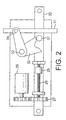
- an electro-mechanical point machine drive unit 10 comprises a prime mover 26, which in this case is a controllable electric motor. This drives, via reduction gear train 27, a linear ballscrew 28, thus converting the rotary motion of the motor to linear movement of ballnut 29 along an axis running from left to right as shown in the figure.
- the linear movement of the ballnut is transferred to drive member 30 at an intermediate point between its two ends.
- Drive member 30 is elongate in the direction of linear movement, so that both ends are capable of protruding beyond the drive unit for at least a portion of the range of travel of the drive member.
- Roller 31 is attached to the drive member 30, and this engages with the profiled end of crank 32; the crank being free to rotate about fixed pivot 33.
- the other arm of the crank is connected to the output drive bar 11 via roller 34.
- the drive bar 11 is connected to the movable rails of a points system (not shown).
- the point machine 10 thus generates two drive outputs which are positioned at right angles to each other.
- One drive 11 is transverse to the railway track whilst the other, drive member 30, is parallel to it.
- the transverse drive output is intermittent, whilst the parallel drive is continuous.
- the phased sequence of drive outputs is achieved by use of the escapement crank 32.
- Both ends of the drive member 30 incorporate means for connection to further drive means, which in turn may engage with further cranks.
- Fig. 3 shows a drive system in which the drive unit 10 is located approximately halfway along the length of the points.
- both ends of the drive member 30 are connected to further drive means 43, 44 which engage with respective cranks 39, 40 via respective rollers 41, 42.
- Fig. 4 shows a further arrangement in which the drive unit 10 is located at the "heel" of the points.
- the drive unit 10 is located at the "heel" of the points.
- only the end of the drive member which is nearest the toe of the points is connected to further drive means.
- Figs. 5 to 7 show arrangements which include more than one drive unit 10 connected via their drive members. This is useful feature which incorporates a level of redundancy into the system, so that failure of a unit is not critical. At busy rail junctions failure of a point mechanism can cause costly delays and disruption to the operating timetable. It is therefore advantageous to have reliable point operating systems that provide the railway operator with immediate response and availability at all times. This may be achieved by introducing a level of redundancy into the system.
- Another problem associated with the use of known multiple point machines is that when the electrical supply has failed and it is required to move the points to their opposite position, it is then usual to revert to manual operation by use of an emergency hand-cranking mechanism incorporated within each machine. Failures of this nature are not a problem when only one point machine is used to drive a set of points, however when there is more than one, each machine has to be operated individually. In order to avoid the problems of switch rail distortion it is necessary to move all machines connected to the switch rails at the same time. To achieve this requires a person at each machine, working in unison to ensure coherency of rail movement.
- the units, and indeed of any supplementary drive elements, such as further drive means 35, 36 in Fig. 3, have their drive members 30, 43, 44 connected together via link arms 45.
- This enables cranks 32 and / or 40 to lock the moveable switch blades in position at each end of movement of drive.
- This locking action is shown typically in Fig. 5, where the system is shown in its quiescent state, with moveable switch blade 2 closed against fixed rail 1. Movement of switch rail 2 away from fixed rail 1 would require rotation of cranks 32 about their pivots 33, however this movement is prevented by rollers 31.
- it will still provide the switch blade locking function.
- the system can still be operated in a coherent manner by use of a single hand crank applied to any one of the units.
- Fig. 5 shows an arrangement where the drive members30 of three drive units 10 are connected together via links 45.
- the arrangement may be used for driving a long point layout such as would be used for high-speed rail vehicles.
- Fig. 6 shows an alternative arrangement whereby two drive units 10 and one supplementary drive element 36 are used in combination.
- two drive units 10 and one supplementary drive element 36 are used in combination.
- many different combinations of units 10 and elements 36 may be envisaged.
- Fig. 7 shows two drive units operating in tandem and positioned between the rails 1, 2, 3, 4 This arrangement is particularly advantageous for underground railways where space is often restricted.
- crank 32 is shown as being housed inside the point machine 10, it is possible for the crank to be separate from it, in a similar manner to the other cranks 39 and 40 shown.
Landscapes
- Engineering & Computer Science (AREA)
- Mechanical Engineering (AREA)
- Transmission Devices (AREA)
- Vehicle Body Suspensions (AREA)
- Valve Device For Special Equipments (AREA)
- Liquid Crystal Substances (AREA)
- Separation By Low-Temperature Treatments (AREA)
- Control Of Multiple Motors (AREA)
- Input Circuits Of Receivers And Coupling Of Receivers And Audio Equipment (AREA)
- Railway Tracks (AREA)
- Power Steering Mechanism (AREA)
Priority Applications (1)
| Application Number | Priority Date | Filing Date | Title |
|---|---|---|---|
| EP08155574A EP1955919A1 (de) | 2004-09-16 | 2005-08-23 | Weichenantriebssystem mit mehreren Antrieben |
Applications Claiming Priority (2)
| Application Number | Priority Date | Filing Date | Title |
|---|---|---|---|
| GB0420618A GB0420618D0 (en) | 2004-09-16 | 2004-09-16 | Point drive system |
| EP05076927A EP1637428A1 (de) | 2004-09-16 | 2005-08-23 | Weichenantriebssystem |
Related Parent Applications (1)
| Application Number | Title | Priority Date | Filing Date |
|---|---|---|---|
| EP05076927A Division EP1637428A1 (de) | 2004-09-16 | 2005-08-23 | Weichenantriebssystem |
Related Child Applications (1)
| Application Number | Title | Priority Date | Filing Date |
|---|---|---|---|
| EP08155574A Division EP1955919A1 (de) | 2004-09-16 | 2005-08-23 | Weichenantriebssystem mit mehreren Antrieben |
Publications (3)
| Publication Number | Publication Date |
|---|---|
| EP1752354A2 true EP1752354A2 (de) | 2007-02-14 |
| EP1752354A3 EP1752354A3 (de) | 2007-02-28 |
| EP1752354B1 EP1752354B1 (de) | 2009-10-14 |
Family
ID=33306695
Family Applications (3)
| Application Number | Title | Priority Date | Filing Date |
|---|---|---|---|
| EP05076927A Withdrawn EP1637428A1 (de) | 2004-09-16 | 2005-08-23 | Weichenantriebssystem |
| EP06076792A Expired - Lifetime EP1752354B1 (de) | 2004-09-16 | 2005-08-23 | Weichenantriebssystem |
| EP08155574A Withdrawn EP1955919A1 (de) | 2004-09-16 | 2005-08-23 | Weichenantriebssystem mit mehreren Antrieben |
Family Applications Before (1)
| Application Number | Title | Priority Date | Filing Date |
|---|---|---|---|
| EP05076927A Withdrawn EP1637428A1 (de) | 2004-09-16 | 2005-08-23 | Weichenantriebssystem |
Family Applications After (1)
| Application Number | Title | Priority Date | Filing Date |
|---|---|---|---|
| EP08155574A Withdrawn EP1955919A1 (de) | 2004-09-16 | 2005-08-23 | Weichenantriebssystem mit mehreren Antrieben |
Country Status (6)
| Country | Link |
|---|---|
| EP (3) | EP1637428A1 (de) |
| AT (1) | ATE445524T1 (de) |
| DE (1) | DE602005017142D1 (de) |
| DK (1) | DK1752354T3 (de) |
| ES (1) | ES2334513T3 (de) |
| GB (1) | GB0420618D0 (de) |
Cited By (1)
| Publication number | Priority date | Publication date | Assignee | Title |
|---|---|---|---|---|
| CN109229144A (zh) * | 2017-07-10 | 2019-01-18 | 比亚迪股份有限公司 | 道岔台车同步控制方法及装置 |
Families Citing this family (4)
| Publication number | Priority date | Publication date | Assignee | Title |
|---|---|---|---|---|
| GB2514420B (en) * | 2013-05-24 | 2017-02-08 | Spx Int Ltd | Railway point crank system |
| JP2016524563A (ja) * | 2013-05-24 | 2016-08-18 | エスピーエックス インターナショナル リミテッド | 鉄道ポイントクランクシステム |
| US9242661B2 (en) | 2013-05-24 | 2016-01-26 | Spx International Limited | Railway point crank system |
| NL1044214B1 (en) * | 2021-11-24 | 2023-06-15 | Kampa B V | Switch drive mechanism for switching a switch rail |
Citations (2)
| Publication number | Priority date | Publication date | Assignee | Title |
|---|---|---|---|---|
| DE104882C (de) | ||||
| EP1512603A2 (de) | 2003-09-04 | 2005-03-09 | Westinghouse Brake And Signal Holdings Limited | Weichenantriebssystem |
Family Cites Families (5)
| Publication number | Priority date | Publication date | Assignee | Title |
|---|---|---|---|---|
| US2168790A (en) * | 1937-11-27 | 1939-08-08 | Union Switch & Signal Co | Railway switch operating apparatus |
| FR1157525A (fr) * | 1956-08-31 | 1958-05-30 | Sncf | Dispositif pour une immobilisation de position semi-dépendante et talonnable des lames d'aiguillages de voies ferrées |
| IN170171B (de) * | 1987-11-05 | 1992-02-22 | Voest Alpine Maschinenbau | |
| AT391500B (de) * | 1987-11-05 | 1990-10-10 | Voest Alpine Ag | Umstellvorrichtung fuer bewegliche teile einer schienenweiche |
| DE20117484U1 (de) * | 2001-10-25 | 2003-03-06 | Hanning & Kahl GmbH & Co., 33813 Oerlinghausen | Umstelleinrichtung für Weichen |
-
2004
- 2004-09-16 GB GB0420618A patent/GB0420618D0/en not_active Ceased
-
2005
- 2005-08-23 EP EP05076927A patent/EP1637428A1/de not_active Withdrawn
- 2005-08-23 EP EP06076792A patent/EP1752354B1/de not_active Expired - Lifetime
- 2005-08-23 AT AT06076792T patent/ATE445524T1/de not_active IP Right Cessation
- 2005-08-23 EP EP08155574A patent/EP1955919A1/de not_active Withdrawn
- 2005-08-23 ES ES06076792T patent/ES2334513T3/es not_active Expired - Lifetime
- 2005-08-23 DK DK06076792T patent/DK1752354T3/da active
- 2005-08-23 DE DE602005017142T patent/DE602005017142D1/de not_active Expired - Lifetime
Patent Citations (2)
| Publication number | Priority date | Publication date | Assignee | Title |
|---|---|---|---|---|
| DE104882C (de) | ||||
| EP1512603A2 (de) | 2003-09-04 | 2005-03-09 | Westinghouse Brake And Signal Holdings Limited | Weichenantriebssystem |
Cited By (2)
| Publication number | Priority date | Publication date | Assignee | Title |
|---|---|---|---|---|
| CN109229144A (zh) * | 2017-07-10 | 2019-01-18 | 比亚迪股份有限公司 | 道岔台车同步控制方法及装置 |
| CN109229144B (zh) * | 2017-07-10 | 2020-07-10 | 比亚迪股份有限公司 | 道岔台车同步控制方法及装置 |
Also Published As
| Publication number | Publication date |
|---|---|
| DE602005017142D1 (de) | 2009-11-26 |
| GB0420618D0 (en) | 2004-10-20 |
| ATE445524T1 (de) | 2009-10-15 |
| ES2334513T3 (es) | 2010-03-11 |
| EP1955919A1 (de) | 2008-08-13 |
| EP1752354B1 (de) | 2009-10-14 |
| DK1752354T3 (da) | 2009-11-30 |
| EP1637428A1 (de) | 2006-03-22 |
| EP1752354A3 (de) | 2007-02-28 |
Similar Documents
| Publication | Publication Date | Title |
|---|---|---|
| CN1750959B (zh) | 铁路及电车轨道用转辙器或类似物的转辙机械 | |
| EP3092340B1 (de) | Eisenbahnweichen, eisenbahnweichenbetriebsvorrichtung und eisenbahnschienenkreuzung | |
| EP1752354B1 (de) | Weichenantriebssystem | |
| CN103144650A (zh) | 转辙机 | |
| CN103693075A (zh) | 单驱动点关节道岔 | |
| HK1095305B (en) | Point drive system | |
| HK1095305A1 (en) | Point drive system | |
| HK1084366A (en) | Point drive system | |
| EP1512603B1 (de) | Weichenantriebssystem mit Kupplungseinrichtung | |
| CN101506024A (zh) | 用于铁路转辙机的液压马达 | |
| JP3895701B2 (ja) | 鉄道分岐器用エスケープクランク | |
| RU2836065C1 (ru) | Переводное устройство пологой стрелки | |
| DE4038339A1 (de) | Stellvorrichtung fuer biegeweichen | |
| JP2791192B2 (ja) | 分岐器転換用駆動装置 | |
| JP2014092277A (ja) | 機械的に同期されるアクチュエータおよび同期方法 | |
| JP6038757B2 (ja) | 発条転てつ機 | |
| RU2826930C1 (ru) | Устройство двухконтурного комбинированного замыкания и двойного контроля положения остряков стрелочных переводов для скоростных железных дорог | |
| GB2516707A (en) | Railway points operating apparatus | |
| RU2826910C1 (ru) | Устройство двухконтурного замыкания и двойного контроля положения остряков стрелочных переводов для скоростных железных дорог | |
| WO2017012971A1 (en) | Mechanical interlock mechanism for electrical devices | |
| RU2192513C2 (ru) | Безостряковый стрелочный перевод | |
| US463579A (en) | Railroad-switch | |
| CN210734155U (zh) | 一种变轨机构 | |
| US714060A (en) | Switch-stand. | |
| RU2501696C2 (ru) | Механизм привода стрелочного перевода |
Legal Events
| Date | Code | Title | Description |
|---|---|---|---|
| PUAI | Public reference made under article 153(3) epc to a published international application that has entered the european phase |
Free format text: ORIGINAL CODE: 0009012 |
|
| PUAL | Search report despatched |
Free format text: ORIGINAL CODE: 0009013 |
|
| 17P | Request for examination filed |
Effective date: 20061019 |
|
| AC | Divisional application: reference to earlier application |
Ref document number: 1637428 Country of ref document: EP Kind code of ref document: P |
|
| AK | Designated contracting states |
Kind code of ref document: A2 Designated state(s): AT BE BG CH CY CZ DE DK EE ES FI FR GB GR HU IE IS IT LI LT LU LV MC NL PL PT RO SE SI SK TR |
|
| AX | Request for extension of the european patent |
Extension state: AL BA HR MK YU |
|
| AK | Designated contracting states |
Kind code of ref document: A3 Designated state(s): AT BE BG CH CY CZ DE DK EE ES FI FR GB GR HU IE IS IT LI LT LU LV MC NL PL PT RO SE SI SK TR |
|
| AX | Request for extension of the european patent |
Extension state: AL BA HR MK YU |
|
| REG | Reference to a national code |
Ref country code: HK Ref legal event code: DE Ref document number: 1095305 Country of ref document: HK |
|
| 17Q | First examination report despatched |
Effective date: 20070404 |
|
| AKX | Designation fees paid |
Designated state(s): AT BE BG CH CY CZ DE DK EE ES FI FR GB GR HU IE IS IT LI LT LU LV MC NL PL PT RO SE SI SK TR |
|
| GRAP | Despatch of communication of intention to grant a patent |
Free format text: ORIGINAL CODE: EPIDOSNIGR1 |
|
| GRAS | Grant fee paid |
Free format text: ORIGINAL CODE: EPIDOSNIGR3 |
|
| GRAA | (expected) grant |
Free format text: ORIGINAL CODE: 0009210 |
|
| AC | Divisional application: reference to earlier application |
Ref document number: 1637428 Country of ref document: EP Kind code of ref document: P |
|
| AK | Designated contracting states |
Kind code of ref document: B1 Designated state(s): AT BE BG CH CY CZ DE DK EE ES FI FR GB GR HU IE IS IT LI LT LU LV MC NL PL PT RO SE SI SK TR |
|
| REG | Reference to a national code |
Ref country code: GB Ref legal event code: FG4D |
|
| REG | Reference to a national code |
Ref country code: CH Ref legal event code: EP |
|
| REG | Reference to a national code |
Ref country code: IE Ref legal event code: FG4D |
|
| REF | Corresponds to: |
Ref document number: 602005017142 Country of ref document: DE Date of ref document: 20091126 Kind code of ref document: P |
|
| REG | Reference to a national code |
Ref country code: DK Ref legal event code: T3 |
|
| REG | Reference to a national code |
Ref country code: HK Ref legal event code: GR Ref document number: 1095305 Country of ref document: HK |
|
| REG | Reference to a national code |
Ref country code: ES Ref legal event code: FG2A Ref document number: 2334513 Country of ref document: ES Kind code of ref document: T3 |
|
| LTIE | Lt: invalidation of european patent or patent extension |
Effective date: 20091014 |
|
| NLV1 | Nl: lapsed or annulled due to failure to fulfill the requirements of art. 29p and 29m of the patents act | ||
| PG25 | Lapsed in a contracting state [announced via postgrant information from national office to epo] |
Ref country code: PT Free format text: LAPSE BECAUSE OF FAILURE TO SUBMIT A TRANSLATION OF THE DESCRIPTION OR TO PAY THE FEE WITHIN THE PRESCRIBED TIME-LIMIT Effective date: 20100215 Ref country code: SE Free format text: LAPSE BECAUSE OF FAILURE TO SUBMIT A TRANSLATION OF THE DESCRIPTION OR TO PAY THE FEE WITHIN THE PRESCRIBED TIME-LIMIT Effective date: 20091014 Ref country code: LT Free format text: LAPSE BECAUSE OF FAILURE TO SUBMIT A TRANSLATION OF THE DESCRIPTION OR TO PAY THE FEE WITHIN THE PRESCRIBED TIME-LIMIT Effective date: 20091014 Ref country code: IS Free format text: LAPSE BECAUSE OF FAILURE TO SUBMIT A TRANSLATION OF THE DESCRIPTION OR TO PAY THE FEE WITHIN THE PRESCRIBED TIME-LIMIT Effective date: 20100214 |
|
| PG25 | Lapsed in a contracting state [announced via postgrant information from national office to epo] |
Ref country code: LV Free format text: LAPSE BECAUSE OF FAILURE TO SUBMIT A TRANSLATION OF THE DESCRIPTION OR TO PAY THE FEE WITHIN THE PRESCRIBED TIME-LIMIT Effective date: 20091014 Ref country code: PL Free format text: LAPSE BECAUSE OF FAILURE TO SUBMIT A TRANSLATION OF THE DESCRIPTION OR TO PAY THE FEE WITHIN THE PRESCRIBED TIME-LIMIT Effective date: 20091014 Ref country code: SI Free format text: LAPSE BECAUSE OF FAILURE TO SUBMIT A TRANSLATION OF THE DESCRIPTION OR TO PAY THE FEE WITHIN THE PRESCRIBED TIME-LIMIT Effective date: 20091014 |
|
| PG25 | Lapsed in a contracting state [announced via postgrant information from national office to epo] |
Ref country code: AT Free format text: LAPSE BECAUSE OF FAILURE TO SUBMIT A TRANSLATION OF THE DESCRIPTION OR TO PAY THE FEE WITHIN THE PRESCRIBED TIME-LIMIT Effective date: 20091014 Ref country code: BE Free format text: LAPSE BECAUSE OF FAILURE TO SUBMIT A TRANSLATION OF THE DESCRIPTION OR TO PAY THE FEE WITHIN THE PRESCRIBED TIME-LIMIT Effective date: 20091014 |
|
| PG25 | Lapsed in a contracting state [announced via postgrant information from national office to epo] |
Ref country code: EE Free format text: LAPSE BECAUSE OF FAILURE TO SUBMIT A TRANSLATION OF THE DESCRIPTION OR TO PAY THE FEE WITHIN THE PRESCRIBED TIME-LIMIT Effective date: 20091014 Ref country code: BG Free format text: LAPSE BECAUSE OF FAILURE TO SUBMIT A TRANSLATION OF THE DESCRIPTION OR TO PAY THE FEE WITHIN THE PRESCRIBED TIME-LIMIT Effective date: 20100114 Ref country code: RO Free format text: LAPSE BECAUSE OF FAILURE TO SUBMIT A TRANSLATION OF THE DESCRIPTION OR TO PAY THE FEE WITHIN THE PRESCRIBED TIME-LIMIT Effective date: 20091014 |
|
| PLBE | No opposition filed within time limit |
Free format text: ORIGINAL CODE: 0009261 |
|
| STAA | Information on the status of an ep patent application or granted ep patent |
Free format text: STATUS: NO OPPOSITION FILED WITHIN TIME LIMIT |
|
| PG25 | Lapsed in a contracting state [announced via postgrant information from national office to epo] |
Ref country code: SK Free format text: LAPSE BECAUSE OF FAILURE TO SUBMIT A TRANSLATION OF THE DESCRIPTION OR TO PAY THE FEE WITHIN THE PRESCRIBED TIME-LIMIT Effective date: 20091014 Ref country code: CZ Free format text: LAPSE BECAUSE OF FAILURE TO SUBMIT A TRANSLATION OF THE DESCRIPTION OR TO PAY THE FEE WITHIN THE PRESCRIBED TIME-LIMIT Effective date: 20091014 |
|
| 26N | No opposition filed |
Effective date: 20100715 |
|
| PG25 | Lapsed in a contracting state [announced via postgrant information from national office to epo] |
Ref country code: GR Free format text: LAPSE BECAUSE OF FAILURE TO SUBMIT A TRANSLATION OF THE DESCRIPTION OR TO PAY THE FEE WITHIN THE PRESCRIBED TIME-LIMIT Effective date: 20100115 |
|
| PGFP | Annual fee paid to national office [announced via postgrant information from national office to epo] |
Ref country code: DE Payment date: 20100528 Year of fee payment: 6 |
|
| PG25 | Lapsed in a contracting state [announced via postgrant information from national office to epo] |
Ref country code: MC Free format text: LAPSE BECAUSE OF NON-PAYMENT OF DUE FEES Effective date: 20100831 Ref country code: IT Free format text: LAPSE BECAUSE OF FAILURE TO SUBMIT A TRANSLATION OF THE DESCRIPTION OR TO PAY THE FEE WITHIN THE PRESCRIBED TIME-LIMIT Effective date: 20091014 |
|
| REG | Reference to a national code |
Ref country code: CH Ref legal event code: PL |
|
| PG25 | Lapsed in a contracting state [announced via postgrant information from national office to epo] |
Ref country code: CH Free format text: LAPSE BECAUSE OF NON-PAYMENT OF DUE FEES Effective date: 20100831 Ref country code: LI Free format text: LAPSE BECAUSE OF NON-PAYMENT OF DUE FEES Effective date: 20100831 |
|
| REG | Reference to a national code |
Ref country code: FR Ref legal event code: ST Effective date: 20110502 |
|
| PG25 | Lapsed in a contracting state [announced via postgrant information from national office to epo] |
Ref country code: FR Free format text: LAPSE BECAUSE OF NON-PAYMENT OF DUE FEES Effective date: 20100831 |
|
| REG | Reference to a national code |
Ref country code: DE Ref legal event code: R119 Ref document number: 602005017142 Country of ref document: DE Effective date: 20120301 |
|
| PG25 | Lapsed in a contracting state [announced via postgrant information from national office to epo] |
Ref country code: CY Free format text: LAPSE BECAUSE OF FAILURE TO SUBMIT A TRANSLATION OF THE DESCRIPTION OR TO PAY THE FEE WITHIN THE PRESCRIBED TIME-LIMIT Effective date: 20091014 |
|
| PG25 | Lapsed in a contracting state [announced via postgrant information from national office to epo] |
Ref country code: LU Free format text: LAPSE BECAUSE OF NON-PAYMENT OF DUE FEES Effective date: 20100823 Ref country code: NL Free format text: LAPSE BECAUSE OF FAILURE TO SUBMIT A TRANSLATION OF THE DESCRIPTION OR TO PAY THE FEE WITHIN THE PRESCRIBED TIME-LIMIT Effective date: 20091014 Ref country code: HU Free format text: LAPSE BECAUSE OF FAILURE TO SUBMIT A TRANSLATION OF THE DESCRIPTION OR TO PAY THE FEE WITHIN THE PRESCRIBED TIME-LIMIT Effective date: 20100415 Ref country code: FI Free format text: LAPSE BECAUSE OF FAILURE TO SUBMIT A TRANSLATION OF THE DESCRIPTION OR TO PAY THE FEE WITHIN THE PRESCRIBED TIME-LIMIT Effective date: 20091014 |
|
| PG25 | Lapsed in a contracting state [announced via postgrant information from national office to epo] |
Ref country code: TR Free format text: LAPSE BECAUSE OF FAILURE TO SUBMIT A TRANSLATION OF THE DESCRIPTION OR TO PAY THE FEE WITHIN THE PRESCRIBED TIME-LIMIT Effective date: 20091014 |
|
| PG25 | Lapsed in a contracting state [announced via postgrant information from national office to epo] |
Ref country code: DE Free format text: LAPSE BECAUSE OF NON-PAYMENT OF DUE FEES Effective date: 20120301 |
|
| REG | Reference to a national code |
Ref country code: ES Ref legal event code: PC2A Owner name: SIEMENS RAIL AUTOMATION HOLDINGS LIMITED Effective date: 20140212 |
|
| PGFP | Annual fee paid to national office [announced via postgrant information from national office to epo] |
Ref country code: DK Payment date: 20140820 Year of fee payment: 10 |
|
| PGFP | Annual fee paid to national office [announced via postgrant information from national office to epo] |
Ref country code: ES Payment date: 20140911 Year of fee payment: 10 |
|
| REG | Reference to a national code |
Ref country code: DK Ref legal event code: EBP Effective date: 20150831 |
|
| PG25 | Lapsed in a contracting state [announced via postgrant information from national office to epo] |
Ref country code: DK Free format text: LAPSE BECAUSE OF NON-PAYMENT OF DUE FEES Effective date: 20150831 |
|
| REG | Reference to a national code |
Ref country code: ES Ref legal event code: FD2A Effective date: 20160926 |
|
| PG25 | Lapsed in a contracting state [announced via postgrant information from national office to epo] |
Ref country code: ES Free format text: LAPSE BECAUSE OF NON-PAYMENT OF DUE FEES Effective date: 20150824 |
|
| PGFP | Annual fee paid to national office [announced via postgrant information from national office to epo] |
Ref country code: IE Payment date: 20240821 Year of fee payment: 20 |
|
| PGFP | Annual fee paid to national office [announced via postgrant information from national office to epo] |
Ref country code: GB Payment date: 20240910 Year of fee payment: 20 |
|
| REG | Reference to a national code |
Ref country code: GB Ref legal event code: PE20 Expiry date: 20250822 |
|
| REG | Reference to a national code |
Ref country code: IE Ref legal event code: MK9A |
|
| PG25 | Lapsed in a contracting state [announced via postgrant information from national office to epo] |
Ref country code: IE Free format text: LAPSE BECAUSE OF EXPIRATION OF PROTECTION Effective date: 20250823 |