EP1756431B1 - Element insonorisant integre a un carter de compresseur - Google Patents
Element insonorisant integre a un carter de compresseur Download PDFInfo
- Publication number
- EP1756431B1 EP1756431B1 EP04739914A EP04739914A EP1756431B1 EP 1756431 B1 EP1756431 B1 EP 1756431B1 EP 04739914 A EP04739914 A EP 04739914A EP 04739914 A EP04739914 A EP 04739914A EP 1756431 B1 EP1756431 B1 EP 1756431B1
- Authority
- EP
- European Patent Office
- Prior art keywords
- compressor housing
- acoustic damper
- damper element
- wall
- compressor
- Prior art date
- Legal status (The legal status is an assumption and is not a legal conclusion. Google has not performed a legal analysis and makes no representation as to the accuracy of the status listed.)
- Expired - Lifetime
Links
- 239000011796 hollow space material Substances 0.000 claims description 11
- 230000010349 pulsation Effects 0.000 claims description 7
- 238000005266 casting Methods 0.000 claims description 3
- 230000000149 penetrating effect Effects 0.000 claims description 2
- 230000004048 modification Effects 0.000 description 5
- 238000012986 modification Methods 0.000 description 5
- 239000007789 gas Substances 0.000 description 4
- 241000237983 Trochidae Species 0.000 description 3
- 238000002485 combustion reaction Methods 0.000 description 3
- 238000004512 die casting Methods 0.000 description 3
- 239000000463 material Substances 0.000 description 3
- 238000000034 method Methods 0.000 description 3
- 238000005219 brazing Methods 0.000 description 2
- 238000004891 communication Methods 0.000 description 2
- 230000006835 compression Effects 0.000 description 2
- 238000007906 compression Methods 0.000 description 2
- 238000004519 manufacturing process Methods 0.000 description 2
- 238000003466 welding Methods 0.000 description 2
- 229910052782 aluminium Inorganic materials 0.000 description 1
- XAGFODPZIPBFFR-UHFFFAOYSA-N aluminium Chemical compound [Al] XAGFODPZIPBFFR-UHFFFAOYSA-N 0.000 description 1
- QVGXLLKOCUKJST-UHFFFAOYSA-N atomic oxygen Chemical compound [O] QVGXLLKOCUKJST-UHFFFAOYSA-N 0.000 description 1
- 230000002238 attenuated effect Effects 0.000 description 1
- 230000005540 biological transmission Effects 0.000 description 1
- 230000000903 blocking effect Effects 0.000 description 1
- 230000010485 coping Effects 0.000 description 1
- 238000013016 damping Methods 0.000 description 1
- 230000003247 decreasing effect Effects 0.000 description 1
- 239000000446 fuel Substances 0.000 description 1
- 238000003754 machining Methods 0.000 description 1
- 229910052751 metal Inorganic materials 0.000 description 1
- 239000002184 metal Substances 0.000 description 1
- 239000001301 oxygen Substances 0.000 description 1
- 229910052760 oxygen Inorganic materials 0.000 description 1
- 239000011347 resin Substances 0.000 description 1
- 229920005989 resin Polymers 0.000 description 1
- 230000003584 silencer Effects 0.000 description 1
- 230000001629 suppression Effects 0.000 description 1
Images


Classifications
-
- F—MECHANICAL ENGINEERING; LIGHTING; HEATING; WEAPONS; BLASTING
- F04—POSITIVE - DISPLACEMENT MACHINES FOR LIQUIDS; PUMPS FOR LIQUIDS OR ELASTIC FLUIDS
- F04D—NON-POSITIVE-DISPLACEMENT PUMPS
- F04D29/00—Details, component parts, or accessories
- F04D29/66—Combating cavitation, whirls, noise, vibration or the like; Balancing
- F04D29/661—Combating cavitation, whirls, noise, vibration or the like; Balancing especially adapted for elastic fluid pumps
- F04D29/663—Sound attenuation
- F04D29/665—Sound attenuation by means of resonance chambers or interference
-
- F—MECHANICAL ENGINEERING; LIGHTING; HEATING; WEAPONS; BLASTING
- F04—POSITIVE - DISPLACEMENT MACHINES FOR LIQUIDS; PUMPS FOR LIQUIDS OR ELASTIC FLUIDS
- F04D—NON-POSITIVE-DISPLACEMENT PUMPS
- F04D29/00—Details, component parts, or accessories
- F04D29/40—Casings; Connections of working fluid
- F04D29/42—Casings; Connections of working fluid for radial or helico-centrifugal pumps
- F04D29/4206—Casings; Connections of working fluid for radial or helico-centrifugal pumps especially adapted for elastic fluid pumps
- F04D29/4213—Casings; Connections of working fluid for radial or helico-centrifugal pumps especially adapted for elastic fluid pumps suction ports
-
- F—MECHANICAL ENGINEERING; LIGHTING; HEATING; WEAPONS; BLASTING
- F04—POSITIVE - DISPLACEMENT MACHINES FOR LIQUIDS; PUMPS FOR LIQUIDS OR ELASTIC FLUIDS
- F04D—NON-POSITIVE-DISPLACEMENT PUMPS
- F04D29/00—Details, component parts, or accessories
- F04D29/66—Combating cavitation, whirls, noise, vibration or the like; Balancing
- F04D29/68—Combating cavitation, whirls, noise, vibration or the like; Balancing by influencing boundary layers
- F04D29/681—Combating cavitation, whirls, noise, vibration or the like; Balancing by influencing boundary layers especially adapted for elastic fluid pumps
- F04D29/685—Inducing localised fluid recirculation in the stator-rotor interface
Definitions
- the present invention relates to an acoustic damper element integrated to a compressor housing for a turbocharger.
- Turbochargers are well known and widely used in connection with combustion engines. Exhaust gas from an engine is supplied to and drives a turbine wheel which drives a compressor wheel. The compressor wheel compresses air and discharges it into combustion chambers of respective cylinders. The thus compressed air contains an increased amount of oxygen per volume unit to enhance the combustion of fuel and thus to generate more power.
- the exhaust gas supplied to the turbine wheel is passed through an inlet and a volute to the turbine wheel and then exits through an outlet with the turbine wheel rotating at a very high speed. The fast rotation of the turbine is transmitted to the compressor wheel so as to compress the air drawn in at the inlet of the compressor housing.
- a bypass port to the compressor inlet typically utilizing a ported shroud configuration.
- a ported shroud provides the inlet of the compressor housing with a primary inlet portion and a secondary inlet portion surrounding the primary inlet portion.
- the secondary inlet portion can activate in addition to the primary inlet portion at a high rotational speed of the compressor wheel to ensure a higher amount of inlet air drawn-in by the compressor wheel.
- the ported shroud is provided with noise deflectors in the secondary inlet portion for reducing the noise transmission therethrough by blocking the linear flow of sound waves and by increasing the length of the path which the sound waves must travel to escape from the compressor.
- one known conventional solution for coping with the Pulsations generated at the compressor outlet resides in providing a hose connected thereto and equipped with a noise suppressor or a silencer, as can be seen in the GB 2 381 834 , as an example.
- modular portions are connected in series to define noise suppression chambers and are then arranged in a hose connected to the compressor outlet.
- a compressor housing according to the preamble of claim 1 is known from DE 197 27 139 A1 .
- noises generated in the compressor housing by the rotation of the compressor wheel or by the compression of the air are efficiently damped very close to the place where the noises are generated.
- the inlet comprises a ported shroud arrangement, wherein the acoustic damper element of the inlet is disposed at the wall of the inlet at an axial position thereof corresponding to the ported shroud arrangement.
- the acoustic damper element may be disposed lengthwise along at least a portion of said wall. Additionally, the acoustic damper element may be in contact with the wall of the inlet or of the outlet of the compressor housing. Furthermore the acoustic damper element may be provided integrally with said wall of the compressor housing, which results in having less parts when assembling a turbocharger utilizing the compressor housing. Preferably, the acoustic damper element is formed by casting it integrally with the compressor housing. This is a very efficient and economic manufacturing method. However, alternatively, the acoustic damper element may be welded, brazed or bonded to the compressor housing.
- the acoustic damper element may be a pulsation type damper element.
- the acoustic damper element may define at least one hollow space inside thereof.
- the acoustic damper element may communicate with the inner side of said wall through holes or openings penetrating said wall. Accordingly, by providing the hollow space with a certain volume and the openings with a certain area and thickness, the frequency range at which the damper is effective can be tuned.
- the hole is provided in the form of a slot extending in a direction perpendicular to an axis of the inlet or the outlet, respectively.
- the a plurality of openings are provided along a line extending in a direction perpendicular to an axis of the inlet or the outlet, respectively.
- the acoustic damper element may at least partly surround said wall.
- the hollow space of the acoustic damper may be divided by at least one wall.
- This provides an acoustic damper element having a plurality of hollow spaces (also called cavities) of a pulsation damper, each being adjusted to a certain noise frequency range by giving the hollow space a certain volume.
- the divided hollow spaces are not directly in communication with each other and each of the divided hollow spaces has at least one respective hole or opening for connecting the hollow space to the inside of the respective wall.
- a compressor housing for accommodating a compressor wheel comprises an inlet and an outlet, each being defined by a wall provided integrally with said compressor housing, wherein at least one acoustic damper element of the Helmholtz type is disposed on the outside of the outlet.
- the acoustic damper element is disposed at a position corresponding to the position of the smallest internal diameter of the outlet.
- the compressor housing according to this aspect of the invention may further comprise all the features defined for the compressor housing according to the first aspect of the invention.
- the acoustic damper element of the Helmholtz type is established based on a mass-spring system represented by the volume of the hollow space as a mass and the volume of the hole or opening as a spring.
- a compressor comprises a compressor housing provided with all the features set forth above for the compressor housing and can accordingly obtain the same advantages.
- a turbocharger has a turbine for driving a compressor wheel accommodated in a compressor housing having all the features set forth above for the compressor housing and can accordingly obtain the same advantages.
- turbocharger may further comprise an electric motor for electrically assisting the driving of the compressor wheel.
- a first exemplary embodiment of an acoustic damper element 1 provided at an inlet 2 of a compressor housing 3 of an electrically assisted turbocharger 4 is explained with reference being made to Figs. 1 to 3 .
- the turbocharger 4 shown in Fig. 1 comprises a turbine housing 5 for accommodating a turbine wheel 6, a center housing 7 for accommodating an electric motor 8 and the compressor housing 3 for accommodating a compressor wheel 9.
- the turbine housing 5 is disposed at the right hand side and the compressor housing is disposed at the left hand side of the center housing 7, respectively.
- a shaft 10 extends through the center housing 3 and connects the turbine wheel 6 to the compressor wheel 9.
- the compressor wheel 9 is driven by the turbine wheel 6 due to the exhaust gas flowing through an inlet and a volute of the turbine housing 5 thus driving the turbine wheel 6.
- the driving of the compressor wheel 9 is assisted by the electric motor 8.
- the driving of the compressor wheel 9 draws air into the compressor housing 3 through the inlet 2, compresses it by passing it through a volute 12 and discharges it at a compressor housing outlet 13.
- the inlet 2 of the compressor housing 3 is formed by a cylindrical outer wall 14 and a cylindrical inner wall 15 which both extend over the left hand side end of blades 11 of the compressor wheel 9, as seen in Fig. 1 .
- the outer wall 14 extends farther to the left hand side than the inner wall 15.
- the outer wall 14 and the inner wall 15 form an annular space 17 which is open to the left hand side and is closed to the right hand side.
- the annular space 17 surrounds the space of the inlet 2 where the compressor wheel 9 is accommodated and communicates with this space through an annular slot 16 of the inner wall 15.
- the blades 11 pass by the annular slot 16 when the compressor wheel 9 rotates.
- the space inside the inner wall 15 is called a primary inlet 18 while the annular space 17 is called a secondary inlet.
- the acoustic damper element 1 is, as can best be seen from Figs. 2 and 3 , disposed at the outer face of the outer wall 14, and is substantially formed like a box comprising curved side walls 19 matching to the outer wall 14 of the compressor housing 3, straight side walls 20 and a top shell wall 21 which is curved to be coaxial to the outer wall 14.
- the acoustic damper element 1 is integrally formed with the compressor housing 3 by casting, e.g. by a die casting process.
- the walls 19, 20 and 21 of the acoustic damper 1 constitute, together with the outer wall 14 of the compressor housing 3, a damper cavity or hollow space 22 which communicates with the annular space 17 via a slot 23 in the outer wall 14.
- the slot 23 extends in a direction perpendicular to the axis of the inlet.
- a Helmhotz type resonator is established with which the frequency range at which the damper element 1 is effective can easily be tuned.
- the amplitude of the acoustic waves corresponding to this frequency range is attenuated and the noises are damped.
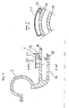
- FIG. 1 Another exemplary embodiment of an acoustic damper element 30 is explained with reference being made to Figs. 1 , 4 and 5 .
- the damper element 30 is provided at the outlet 13 of the compressor housing 3, as can best be seen in Figs. 1 and 4 .
- the acoustic damper element 30 has substantially the same configuration as that of the inlet damper in the preceding embodiment and comprises side walls and a top shell wall.
- the damper element 30 is arranged at the outside of a wall 31 of the outlet 13.
- the wall 31 is provided with a slot 32 connecting the inside of the outlet 31 to a cavity 33 formed inside the acoustic damper element 30.
- a Helmholtz type resonator which is based on a mass-spring system represented by the volume of the cavity 33 as a mass and the volume of the slot 33 as a spring.
- the acoustic damper element 30 is integrally formed with the outlet 13 of the compressor housing 3 by a die casting process.
- the acoustic damper element 30 is tuned to be effective to a certain frequency range of a source of noise (Pulsation) inside the outlet 13 by giving the cavity 33 a certain volume and the slot 32 a certain opening area and thickness (radial length).
- Known frequencies of acoustic waves occurring at the compressor outlet range between 1000 Hz and the frequency at the maximum speed of the compressor wheel.
- Fig. 6 shows a modification of the exemplary embodiment of Fig. 5 .
- a second acoustic damper element 40 is provided at a position at the outside of the outlet 13 and radially opposite to the position of the acoustic damper element 30.
- the second acoustic damper element 40 is structured similar to the acoustic damper element 30 and comprises side walls and a top shell wall.
- a second slot 42 in the wall 31 of the outlet 13 connects the inside of the outlet 13 to a cavity 43 formed in the acoustic damper element 40.
- the second acoustic damper element 40 differs from the acoustic damper element 30 in that the cavity 43 and the slot 42 have different dimensions as compared to the cavity 33 and the slot 32, respectively.
- the frequency range at which the second acoustic damper element 40 is effective is different from that at which the acoustic damper element 30 is effective. Therefore, pulsation noises of different frequency ranges can appropriately be damped at the outlet 13 of the compressor housing 3.
- the compressor housing can be equipped with an acoustic damper element only at the inlet or only at the outlet.
- the compressor housing can be equipped with at least one acoustic damper element at each of these parts, i.e. at the inlet and at the outlet.
- the acoustic damper element may be provided with a plurality of cavities or hollow spaces separated from each other by separating walls.
- Each cavity can be in communication with the inside of the respective part, i.e. the inlet or the outlet, by a respective slot and each cavity/slot pair may be tuned to a certain frequency range.
- each cavity of the damper may be connected to the inside of the respective part (inlet or outlet) by a plurality of slots.
- the acoustic damper element is integrally formed with the compressor housing by a die casting process.
- the material used for the acoustic damper element may be any material used for the compressor housing, such as aluminum.
- the acoustic damper element may also be prepared as a separate member and may be fixed to the compressor housing by welding, brazing or bonding.
- the material used for the acoustic damper element may be metal or resin.
- the acoustic damper element may also partly be cast by forming the walls around the cavity together with the compressor housing, then machining the slot into the wall of the compressor housing and finally mounting the top wall to the side walls by welding, brazing or bonding.
Landscapes
- Engineering & Computer Science (AREA)
- Mechanical Engineering (AREA)
- General Engineering & Computer Science (AREA)
- Structures Of Non-Positive Displacement Pumps (AREA)
- Supercharger (AREA)
Claims (16)
- Carter de compresseur (3) destiné à recevoir une roue de compresseur (9), le carter de compresseur (3) ayant une entrée (2) et une sortie (13), chacune étant définie par une paroi (14 ; 31) prévue intégralement dans ledit carter de compresseur (3), l'entrée (2) comprenant en outre un agencement d'enceinte à orifices (15, 16, 17), au moins un élément amortisseur insonorisant (1) étant disposé sur l'extérieur de l'entrée (2),
caractérisé en ce que
l'élément amortisseur insonorisant (1) est un élément amortisseur de type à impulsions, l'élément amortisseur insonorisant (1) de l'entrée étant disposé au niveau de ladite paroi (14) de l'entrée (2) en une position axiale de celle-ci qui correspond à l'agencement d'enceinte à orifices (15, 16, 17). - Carter de compresseur (3) selon la revendication 1, dans lequel l'élément amortisseur insonorisant (1) est disposé en longueur le long d'au moins une portion de ladite paroi (14).
- Carter de compresseur (3) selon l'une quelconque des revendications 1 à 2, dans lequel l'élément amortisseur insonorisant (1) est en contact avec ladite paroi (14) du carter de compresseur (3).
- Carter de compresseur (3) selon l'une quelconque des revendications 1 à 3, dans lequel l'élément amortisseur insonorisant (1) est prévu intégralement dans ladite paroi (14) du carter de compresseur (3).
- Carter de compresseur (3) selon l'une quelconque des revendications 1 à 4, dans lequel l'élément amortisseur insonorisant (1) est formé par moulage intégral avec le carter de compresseur (3).
- Carter de compresseur (3) selon l'une quelconque des revendications 1 à 3, dans lequel l'élément amortisseur insonorisant (1) est soudé ou brasé au carter de compresseur (3).
- Carter de compresseur (3) selon l'une quelconque des revendications 1 à 6, dans lequel l'élément amortisseur insonorisant (1) définit au moins un espace creux (22) à l'intérieur de celui-ci.
- Carter de compresseur (3) selon l'une quelconque des revendications 1 à 7, dans lequel l'espace creux (22) de l'élément amortisseur insonorisant (1) communique avec le côté interne de ladite paroi (14) à travers au moins une ouverture (23) traversant ladite paroi (14).
- Carter de compresseur (3) selon la revendication 8, dans lequel ladite ouverture (23) est une fente s'étendant dans une direction perpendiculaire à un axe de l'entrée.
- Carter de compresseur (3) selon la revendication 8, dans lequel une pluralité d'ouvertures (23) est disposée sur une ligne s'étendant dans une direction perpendiculaire à un axe de l'entrée (2).
- Carter de compresseur (3) selon l'une quelconque des revendications 1 à 10, dans lequel l'élément amortisseur insonorisant (1) entoure au moins partiellement ladite paroi (14).
- Carter de compresseur (3) selon l'une quelconque des revendications 7 à 11, dans lequel l'espace creux (22) de l'élément amortisseur insonorisant (1) est divisé par au moins une paroi.
- Carter de compresseur (3) selon la revendication 12, dans lequel les espaces creux divisés (22) communiquent avec le côté interne de la paroi (14) par des ouvertures correspondantes séparées dans la paroi (14).
- Compresseur ayant un carter de compresseur (3) selon l'une quelconque des revendications 1 à 13.
- Turbocompresseur ayant une turbine et un compresseur selon la revendication 14.
- Turbocompresseur selon la revendication 15, comprenant en outre un moteur électrique (8) pour l'assistance électrique de l'entraînement de la roue du compresseur (9).
Applications Claiming Priority (1)
| Application Number | Priority Date | Filing Date | Title |
|---|---|---|---|
| PCT/EP2004/006445 WO2005124159A1 (fr) | 2004-06-15 | 2004-06-15 | Element insonorisant integre a un carter de compresseur |
Publications (2)
| Publication Number | Publication Date |
|---|---|
| EP1756431A1 EP1756431A1 (fr) | 2007-02-28 |
| EP1756431B1 true EP1756431B1 (fr) | 2009-03-11 |
Family
ID=34957857
Family Applications (1)
| Application Number | Title | Priority Date | Filing Date |
|---|---|---|---|
| EP04739914A Expired - Lifetime EP1756431B1 (fr) | 2004-06-15 | 2004-06-15 | Element insonorisant integre a un carter de compresseur |
Country Status (5)
| Country | Link |
|---|---|
| US (1) | US8272834B2 (fr) |
| EP (1) | EP1756431B1 (fr) |
| CN (1) | CN100520085C (fr) |
| DE (1) | DE602004019986D1 (fr) |
| WO (1) | WO2005124159A1 (fr) |
Families Citing this family (35)
| Publication number | Priority date | Publication date | Assignee | Title |
|---|---|---|---|---|
| FR2881191B1 (fr) * | 2005-01-25 | 2010-10-15 | Renault Sas | Dispositif de suralimentation d'un moteur a combustion interne comprenant une chambre d'amortissement des pulsations |
| WO2006090152A1 (fr) | 2005-02-23 | 2006-08-31 | Cummins Turbo Technologies Limited | Compresseur |
| DE102006003599A1 (de) * | 2006-01-25 | 2007-08-16 | Siemens Ag | Kompressorgehäuse für einen Abgasturbolader |
| US7624575B2 (en) | 2006-12-08 | 2009-12-01 | Honeywell International Inc. | EGR mixer and ported shroud compressor housing |
| GB0701012D0 (en) * | 2007-01-19 | 2007-02-28 | Cummins Turbo Tech Ltd | Compressor |
| US7794213B2 (en) * | 2007-05-14 | 2010-09-14 | Honeywell International Inc. | Integrated acoustic damper with thin sheet insert |
| JP5351401B2 (ja) * | 2007-09-28 | 2013-11-27 | 三菱重工業株式会社 | 圧縮機 |
| EP2063130A1 (fr) * | 2007-11-20 | 2009-05-27 | Siemens Aktiengesellschaft | Dispositif d'atténuation de bruit pour un compresseur centrifuge |
| DE102008047506A1 (de) * | 2008-09-17 | 2010-04-15 | Daimler Ag | Radialverdichter, insbesondere für einen Abgasturbolader einer Brennkraftmaschine |
| CN102405338A (zh) * | 2009-05-18 | 2012-04-04 | 博格华纳公司 | 排气涡轮增压器的压缩机 |
| DE102009051104A1 (de) * | 2009-10-28 | 2011-05-05 | Mann + Hummel Gmbh | Radialverdichter |
| US20110103978A1 (en) * | 2009-10-30 | 2011-05-05 | Wagner Spray Tech Corporation | Turbine with improved sound reduction |
| WO2011084283A2 (fr) * | 2009-12-17 | 2011-07-14 | Borgwarner Inc. | Turbocompresseur |
| EP2535595B1 (fr) * | 2010-02-09 | 2019-04-17 | IHI Corporation | Compresseur centrifuge faisant appel à un traitement pour carter à recirculation automatique asymétrique |
| JP5620690B2 (ja) * | 2010-02-15 | 2014-11-05 | 株式会社マキタ | ブロワ |
| DE102011005025A1 (de) * | 2011-03-03 | 2012-09-06 | Siemens Aktiengesellschaft | Resonatorschalldämpfer für eine radiale Strömungsmaschine, insbesondere für einen Radialverdichter |
| CN102588351A (zh) * | 2012-01-03 | 2012-07-18 | 大同北方天力增压技术有限公司 | 一种用于涡轮增压器离心式压缩机的低噪音装置 |
| DE102012202707B3 (de) * | 2012-02-22 | 2013-03-07 | Siemens Aktiengesellschaft | Laufradseitenräume mit Resonatoren bei radialen Strömungsmaschinen |
| WO2013133979A1 (fr) * | 2012-03-06 | 2013-09-12 | Borgwarner Inc. | Turbocompresseur à gaz d'échappement |
| US10337529B2 (en) | 2012-06-20 | 2019-07-02 | Ford Global Technologies, Llc | Turbocharger compressor noise reduction system and method |
| US9303561B2 (en) | 2012-06-20 | 2016-04-05 | Ford Global Technologies, Llc | Turbocharger compressor noise reduction system and method |
| DE112014000290T5 (de) * | 2013-01-23 | 2015-10-15 | Borgwarner Inc. | Akustik-Messvorrichtung |
| DE202013004850U1 (de) * | 2013-05-27 | 2013-06-05 | Thermo Electron Led Gmbh | Laborzentrifuge mit gedämmtem Kompressor |
| US20160363136A1 (en) * | 2014-01-31 | 2016-12-15 | Borgwarner Inc. | Method of retaining a noise attenuation device in a compressor cover |
| DE102014206114A1 (de) * | 2014-04-01 | 2015-10-01 | Mahle International Gmbh | Gehäuse eines Radialgebläses |
| CN104131888A (zh) * | 2014-08-15 | 2014-11-05 | 无锡科博增压器有限公司 | 增压器出口用减噪装置 |
| US10260643B2 (en) | 2014-12-02 | 2019-04-16 | United Technologies Corporation | Bleed valve resonator drain |
| US10393384B2 (en) * | 2015-06-09 | 2019-08-27 | Rolls-Royce North American Technologies Inc. | Wave rotor with canceling resonator |
| RU2750512C2 (ru) * | 2016-11-04 | 2021-06-29 | Форд Глобал Текнолоджиз, Ллк | Система и способ для снижения шума компрессора турбонагнетателя |
| US10473120B2 (en) * | 2017-03-09 | 2019-11-12 | Denso International America, Inc. | Blower assembly having resonators and resonator assembly |
| US10309417B2 (en) | 2017-05-12 | 2019-06-04 | Borgwarner Inc. | Turbocharger having improved ported shroud compressor housing |
| US10316859B2 (en) | 2017-05-12 | 2019-06-11 | Borgwarner Inc. | Turbocharger having improved ported shroud compressor housing |
| CN109184897A (zh) * | 2018-09-29 | 2019-01-11 | 重庆长安汽车股份有限公司 | 一种电控涡轮增压器及布置结构 |
| US10900498B1 (en) * | 2019-09-06 | 2021-01-26 | Ford Global Technologies, Llc | Compressor and method for operation of a compressor |
| US12000410B2 (en) * | 2022-05-27 | 2024-06-04 | Toyota Motor Engineering & Manufacturing North America, Inc. | Shroud for an air moving device |
Family Cites Families (15)
| Publication number | Priority date | Publication date | Assignee | Title |
|---|---|---|---|---|
| US4930979A (en) * | 1985-12-24 | 1990-06-05 | Cummins Engine Company, Inc. | Compressors |
| DE4219249C2 (de) * | 1992-06-12 | 1994-03-31 | Kuehnle Kopp Kausch Ag | Radialverdichter, insbesondere eines Turboladers |
| US5295785A (en) * | 1992-12-23 | 1994-03-22 | Caterpillar Inc. | Turbocharger having reduced noise emissions |
| DE19514990B4 (de) * | 1995-04-24 | 2005-06-30 | Abb Turbo Systems Ag | Filterschalldämpfer |
| DE19727139C2 (de) * | 1997-06-26 | 2000-04-20 | Daimler Chrysler Ag | Verdichter eines Abgasturboladers |
| NL1006892C2 (nl) * | 1997-08-29 | 1999-03-02 | Q E International Bv | Pulsatiedemper. |
| DE10000418A1 (de) * | 2000-01-07 | 2001-08-09 | Abb Turbo Systems Ag Baden | Verdichter eines Abgasturboladers |
| JP4276363B2 (ja) * | 2000-07-31 | 2009-06-10 | 株式会社小松製作所 | ファン装置の騒音低減機構に用いられる多孔質吸音材の成形方法 |
| US6530221B1 (en) * | 2000-09-21 | 2003-03-11 | Siemens Westinghouse Power Corporation | Modular resonators for suppressing combustion instabilities in gas turbine power plants |
| US6623239B2 (en) * | 2000-12-13 | 2003-09-23 | Honeywell International Inc. | Turbocharger noise deflector |
| DE10112764A1 (de) * | 2001-03-16 | 2002-09-19 | Mann & Hummel Filter | Radialverdichter |
| EP1473465B2 (fr) * | 2003-04-30 | 2018-08-01 | Holset Engineering Company Limited | Compresseur |
| EP1473463B1 (fr) * | 2003-04-30 | 2006-08-16 | Holset Engineering Co. Limited | Compresseur |
| WO2006090152A1 (fr) * | 2005-02-23 | 2006-08-31 | Cummins Turbo Technologies Limited | Compresseur |
| US7942625B2 (en) * | 2007-04-04 | 2011-05-17 | Honeywell International, Inc. | Compressor and compressor housing |
-
2004
- 2004-06-15 WO PCT/EP2004/006445 patent/WO2005124159A1/fr not_active Ceased
- 2004-06-15 DE DE602004019986T patent/DE602004019986D1/de not_active Expired - Lifetime
- 2004-06-15 US US11/629,438 patent/US8272834B2/en not_active Expired - Fee Related
- 2004-06-15 CN CNB2004800437978A patent/CN100520085C/zh not_active Expired - Fee Related
- 2004-06-15 EP EP04739914A patent/EP1756431B1/fr not_active Expired - Lifetime
Also Published As
| Publication number | Publication date |
|---|---|
| WO2005124159A1 (fr) | 2005-12-29 |
| EP1756431A1 (fr) | 2007-02-28 |
| CN101002026A (zh) | 2007-07-18 |
| CN100520085C (zh) | 2009-07-29 |
| US20080292449A1 (en) | 2008-11-27 |
| DE602004019986D1 (de) | 2009-04-23 |
| US8272834B2 (en) | 2012-09-25 |
Similar Documents
| Publication | Publication Date | Title |
|---|---|---|
| EP1756431B1 (fr) | Element insonorisant integre a un carter de compresseur | |
| JP5043686B2 (ja) | 圧縮機 | |
| CN104204532B (zh) | 制冷剂压缩机 | |
| JP4772272B2 (ja) | 音響ライナー、流体圧縮装置およびその使用方法 | |
| US6623239B2 (en) | Turbocharger noise deflector | |
| JPH06207563A (ja) | 排気ターボ過給機 | |
| JPH11315784A (ja) | 流体機械 | |
| CN103696968B (zh) | 用于罗茨式增压器的一体谐振器 | |
| JP2009264205A (ja) | 遠心圧縮機 | |
| CN111322276A (zh) | 包括用于衰减压缩机的噪声的消声器的涡轮增压器系统 | |
| KR100604013B1 (ko) | 공기 안내 시스템, 특히 내연 기관의 흡기 시스템 | |
| CN101163866B (zh) | 压缩机消声器 | |
| CN101163890B (zh) | 压缩机 | |
| JP4333378B2 (ja) | 過給機用吸入消音器の騒音放出低減方法及び装置 | |
| WO2017094426A1 (fr) | Mécanisme de support de moteur électrique, compresseur, et compresseur d'alimentation | |
| US11920596B2 (en) | Screw compressor configured to compress a process gas and dampen pulsation waves | |
| EP2476906B1 (fr) | Compresseur à air | |
| JPH01208590A (ja) | 圧縮機 | |
| KR20070020517A (ko) | 컴프레서 하우징과 통합된 음향 댐퍼 | |
| JPH02196189A (ja) | 圧縮機 | |
| CN223868127U (zh) | 消音装置及压缩机 | |
| JP5607492B2 (ja) | 負圧ポンプ | |
| JPH10169554A (ja) | 密閉型圧縮機 | |
| CN119957460A (zh) | 消音装置及压缩机 | |
| CN113982946A (zh) | 压缩机和制冷设备 |
Legal Events
| Date | Code | Title | Description |
|---|---|---|---|
| PUAI | Public reference made under article 153(3) epc to a published international application that has entered the european phase |
Free format text: ORIGINAL CODE: 0009012 |
|
| 17P | Request for examination filed |
Effective date: 20061115 |
|
| AK | Designated contracting states |
Kind code of ref document: A1 Designated state(s): DE FR GB |
|
| DAX | Request for extension of the european patent (deleted) | ||
| RBV | Designated contracting states (corrected) |
Designated state(s): DE FR GB |
|
| 17Q | First examination report despatched |
Effective date: 20080307 |
|
| GRAP | Despatch of communication of intention to grant a patent |
Free format text: ORIGINAL CODE: EPIDOSNIGR1 |
|
| GRAS | Grant fee paid |
Free format text: ORIGINAL CODE: EPIDOSNIGR3 |
|
| GRAA | (expected) grant |
Free format text: ORIGINAL CODE: 0009210 |
|
| AK | Designated contracting states |
Kind code of ref document: B1 Designated state(s): DE FR GB |
|
| REG | Reference to a national code |
Ref country code: GB Ref legal event code: FG4D |
|
| REF | Corresponds to: |
Ref document number: 602004019986 Country of ref document: DE Date of ref document: 20090423 Kind code of ref document: P |
|
| PLBE | No opposition filed within time limit |
Free format text: ORIGINAL CODE: 0009261 |
|
| STAA | Information on the status of an ep patent application or granted ep patent |
Free format text: STATUS: NO OPPOSITION FILED WITHIN TIME LIMIT |
|
| 26N | No opposition filed |
Effective date: 20091214 |
|
| REG | Reference to a national code |
Ref country code: FR Ref legal event code: PLFP Year of fee payment: 12 |
|
| PGFP | Annual fee paid to national office [announced via postgrant information from national office to epo] |
Ref country code: GB Payment date: 20150526 Year of fee payment: 12 |
|
| PGFP | Annual fee paid to national office [announced via postgrant information from national office to epo] |
Ref country code: FR Payment date: 20150528 Year of fee payment: 12 |
|
| PGFP | Annual fee paid to national office [announced via postgrant information from national office to epo] |
Ref country code: DE Payment date: 20150630 Year of fee payment: 12 |
|
| REG | Reference to a national code |
Ref country code: DE Ref legal event code: R119 Ref document number: 602004019986 Country of ref document: DE |
|
| GBPC | Gb: european patent ceased through non-payment of renewal fee |
Effective date: 20160615 |
|
| REG | Reference to a national code |
Ref country code: FR Ref legal event code: ST Effective date: 20170228 |
|
| PG25 | Lapsed in a contracting state [announced via postgrant information from national office to epo] |
Ref country code: DE Free format text: LAPSE BECAUSE OF NON-PAYMENT OF DUE FEES Effective date: 20170103 Ref country code: FR Free format text: LAPSE BECAUSE OF NON-PAYMENT OF DUE FEES Effective date: 20160630 |
|
| PG25 | Lapsed in a contracting state [announced via postgrant information from national office to epo] |
Ref country code: GB Free format text: LAPSE BECAUSE OF NON-PAYMENT OF DUE FEES Effective date: 20160615 |