EP1758228A1 - Motor - Google Patents
Motor Download PDFInfo
- Publication number
- EP1758228A1 EP1758228A1 EP05730558A EP05730558A EP1758228A1 EP 1758228 A1 EP1758228 A1 EP 1758228A1 EP 05730558 A EP05730558 A EP 05730558A EP 05730558 A EP05730558 A EP 05730558A EP 1758228 A1 EP1758228 A1 EP 1758228A1
- Authority
- EP
- European Patent Office
- Prior art keywords
- terminal block
- circuit board
- housing
- motor
- board
- Prior art date
- Legal status (The legal status is an assumption and is not a legal conclusion. Google has not performed a legal analysis and makes no representation as to the accuracy of the status listed.)
- Withdrawn
Links
Images


Classifications
-
- H—ELECTRICITY
- H02—GENERATION; CONVERSION OR DISTRIBUTION OF ELECTRIC POWER
- H02K—DYNAMO-ELECTRIC MACHINES
- H02K3/00—Details of windings
- H02K3/46—Fastening of windings on the stator or rotor structure
- H02K3/52—Fastening salient pole windings or connections thereto
- H02K3/521—Fastening salient pole windings or connections thereto applicable to stators only
- H02K3/522—Fastening salient pole windings or connections thereto applicable to stators only for generally annular cores with salient poles
-
- H—ELECTRICITY
- H02—GENERATION; CONVERSION OR DISTRIBUTION OF ELECTRIC POWER
- H02K—DYNAMO-ELECTRIC MACHINES
- H02K11/00—Structural association of dynamo-electric machines with electric components or with devices for shielding, monitoring or protection
- H02K11/20—Structural association of dynamo-electric machines with electric components or with devices for shielding, monitoring or protection for measuring, monitoring, testing, protecting or switching
- H02K11/21—Devices for sensing speed or position, or actuated thereby
- H02K11/215—Magnetic effect devices, e.g. Hall-effect or magneto-resistive elements
-
- H—ELECTRICITY
- H02—GENERATION; CONVERSION OR DISTRIBUTION OF ELECTRIC POWER
- H02K—DYNAMO-ELECTRIC MACHINES
- H02K21/00—Synchronous motors having permanent magnets; Synchronous generators having permanent magnets
- H02K21/12—Synchronous motors having permanent magnets; Synchronous generators having permanent magnets with stationary armatures and rotating magnets
- H02K21/22—Synchronous motors having permanent magnets; Synchronous generators having permanent magnets with stationary armatures and rotating magnets with magnets rotating around the armatures, e.g. flywheel magnetos
-
- H—ELECTRICITY
- H02—GENERATION; CONVERSION OR DISTRIBUTION OF ELECTRIC POWER
- H02K—DYNAMO-ELECTRIC MACHINES
- H02K29/00—Motors or generators having non-mechanical commutating devices, e.g. discharge tubes or semiconductor devices
- H02K29/06—Motors or generators having non-mechanical commutating devices, e.g. discharge tubes or semiconductor devices with position sensing devices
- H02K29/08—Motors or generators having non-mechanical commutating devices, e.g. discharge tubes or semiconductor devices with position sensing devices using magnetic effect devices, e.g. Hall-plates, magneto-resistors
-
- H—ELECTRICITY
- H02—GENERATION; CONVERSION OR DISTRIBUTION OF ELECTRIC POWER
- H02K—DYNAMO-ELECTRIC MACHINES
- H02K5/00—Casings; Enclosures; Supports
- H02K5/04—Casings or enclosures characterised by the shape, form or construction thereof
- H02K5/22—Auxiliary parts of casings not covered by groups H02K5/06-H02K5/20, e.g. shaped to form connection boxes or terminal boxes
- H02K5/225—Terminal boxes or connection arrangements
-
- H—ELECTRICITY
- H02—GENERATION; CONVERSION OR DISTRIBUTION OF ELECTRIC POWER
- H02K—DYNAMO-ELECTRIC MACHINES
- H02K2211/00—Specific aspects not provided for in the other groups of this subclass relating to measuring or protective devices or electric components
- H02K2211/03—Machines characterised by circuit boards, e.g. pcb
Definitions
- the present invention relates to an electric motor provided with a rotation sensor detecting a rotational position of a rotor.
- Electric motors include a type in which motor coils are connected via an insulating terminal block to an external circuit.
- a rotational position detecting circuit is provided integrally in the terminal block so that efficiency in assembly of the terminal block to the motor is improved.
- Hall elements serving as a rotation sensor and a heat sensitive element serving as a temperature sensor are fitted into element mounting portions after an electrically conductive plate has been formed by insert molding in the forming of the terminal block.
- a secondary formation is then carried out so that the rotational position detecting circuit is formed integrally.
- Japanese Patent No. 3497684 discloses an electric motor constructed as described above, for example.
- shrinkage of resin after the primary formation sometimes reduces dimensional accuracy of each element mounting portion.
- Reduction in the dimensional accuracy of each element mounting portion results in reduction in the mounting accuracy of the Hall elements, thereby reducing a detection accuracy of rotational position of the rotor.
- An object of the present invention is to provide an electric motor in which accuracy in positioning the rotation sensor relative to the terminal block can be improved in an arrangement that motor coils are connected via the terminal block to an external circuit.
- the present invention is an electric motor which comprises a stator, a rotor having a field permanent magnet, a terminal block fixed to the stator, and a magnetism detecting circuit detecting magnetism of the field permanent magnet, thereby detecting a rotational position of the rotor, characterized in that the magnetism detecting circuit includes a circuit board provided in the terminal block and a rotation sensor which is attached to the circuit board while being held by a sensor case, and the sensor case includes a positioning portion the rotation sensor relative to the terminal block when the circuit board has been provided in the terminal block.
- the magnetism detecting circuit can easily be mounted on the terminal block since the magnetism detecting circuit comprises the circuit board. Furthermore, the rotation sensor can be positioned via the sensor case relative to the terminal block easily and accurately only when the circuit board is provided in the terminal block.
- FIGS. 1 to 6 illustrate one embodiment in which the invention is applied to a DC brushless motor of the outer rotor type for driving a rotating tub of a washing machine, for example.
- the motor 1 of the embodiment comprises a stator 2 and a rotor 3.
- the rotor 3 includes a frame 4 made from a magnetic material into the shape of a shallow dish, an annular rotor core 5 disposed along an inner circumferential surface of a circumferential wall of the frame 4, and magnetic field permanent magnets 6 disposed on the inner circumference of the rotor core 5.
- Magnet insertion holes 7 are provided in the inner circumference of the rotor core 5.
- the magnetic field permanent magnets 6 are inserted in the magnet insertion holes 7 respectively.
- the rotor core 5, the magnetic field permanent magnets 6 and the frame 4 are integrated by molded resin 8 (shown only in FIG. 2).
- On a central part of the frame 4 is provided a boss 9 to be coupled to an end of a rotating tub shaft which is not shown.
- the stator 2 includes a stator core 11 having a number of radially extending teeth 10, an insulating cover 12 covering the stator core 11 and coils13 wound on portions of the insulating cover 12 covering the teeth 10.
- Each coil 13 comprises three coil wires 13a (shown only in FIG. 2).
- the stator core 11 is made by stacking a plurality of steel sheets.
- the insulating cover 12 is made from a non-conductive synthetic resin and comprises a pair of covering members sandwiching the stator core 11 from both axial sides.
- a terminal block 15 and a terminal block assembly 16 are attached to an end face (hereinafter, "upper end face") of both axial end faces of the insulating cover 12 unopposed to the frame 4.
- the terminal block 15 and the terminal block assembly 16 are provided so that ends of the coil wires 13a are easily connected to an external circuit (not shown).
- a plurality of engagement portions are provided on the upper end face of the insulating cover 12.
- the terminal block 15 and the terminal block assembly 16 have engaged portions 18 respectively.
- the engaged portions 18 are engaged with the engagement portions 17 respectively so that the terminal block 15 and the terminal block assembly 16 are fixed to the insulating cover 12.
- housing portions 19 are formed integrally in the portion of the upper end face of the insulating cover 12 to which portion the terminal block 15 and the terminal block assembly 16 are attached.
- the housing portions 19 are disposed along the inner circumference of the insulating cover 12.
- One ends (terminal for external connection) of the respective coil wires 13a are inserted into three of the six housing portions 19 located under the terminal block 15.
- the terminal block 15 is made from non-conductive synthetic resin.
- Three housing portions 20 are formed integrally in a lower face of the terminal block 15 (a face opposed to the insulating cover 12).
- a common connection conductive plate (not shown) is embedded in the terminal block 15.
- a connecting portion which is an end of the conductive plate protrudes into the housings 20.
- the terminal block assembly 16 includes a terminal block 21 comprising a non-conductive synthetic resin and a circuit board 22 provided integrally on the terminal block 21.
- the terminal block 21 includes a portion located on the insulating cover 12 and a portion protruding from the insulating cover 12.
- Three housing portions 23 are formed integrally in the underside of a portion of the terminal block 21 located on the insulating cover 12 (surface opposed to the insulating cover).
- the conductive plates 24 are embedded in the terminal block 21.
- the conductive plates 24 have respective one ends provided with connecting portions (not shown) projecting into the housing portions 23.
- the housing portions 23 are adapted to be fitted with the three housing portions 10 located lower as viewed FIG. 2, whereby the connecting portion and the external connection terminals are electrically connected together.
- a rectangular cylindrical connector 25 and a board housing portion 27 are formed integrally on an outer circumferential upper surface of the portion of the terminal block 21 protruding from the insulating cover 12.
- the board housing portion 27 is defined by a rectangular cylindrical housing wall 26.
- the conductive plates 24 have the other ends located in the connector 25. Accordingly, when a connector (not shown) of an external circuit is fitted into the connector 25, the three conductive plates 24 are connected to the external circuit.
- a rectangular plate-shaped circuit board 22 is housed in the board housing portion 27.
- the housing wall 26 has an inner circumferential surface provided with a plurality of claws 26a engaging a circumferential edge of the circuit board 22. Some of the claws 26a engage one of sides of the circuit board 22 and the other claws 26a engage the other side of the circuit board 22.
- the circuit board 22 is fixed in the board housing portion 27.
- a magnetism detecting circuit (not shown) comprising a diode 28, a capacitor 29, Hall elements 30 serving as a rotation sensor, and the like.
- the diode 28 and the capacitor 29 are provided on one side of the circuit board 22 and have respective lead wires 28a and 29a soldered to the circuit board 22.
- a connector 31 is provided on an end of one side of the circuit board 22.
- An external connection conductive plate 32 has one end protruding into the connector 31. The other end of the conductive plate 32 is soldered to the circuit board 22.
- the housing wall 26 is provided with a multiple wall 26b located at both sides of the connector 31 when the circuit board 22 is placed in the circuit housing 27 and an opening 26c corresponding to an end of the connector 31.
- An element case 33 (serving as a sensor case) made from a resin is mounted on an end of the other side of the circuit board 22 for the purpose of holding the Hall elements 30.
- the element case 33 has two juxtaposed housings 34 in which the Hall elements 30 are adapted to be held therein as shown in FIGS. 5 and 6.
- the Hall elements 30 are provided for detecting a rotational position of the rotor 3.
- the Hall elements 30 have lead wires 30a soldered to the circuit board 22.
- the element case 33 has a side which is opposed to openings of the housings 34 and formed into a gentle arc face 33a.
- a fitting protrusion 35 is provided integrally on a central part of the mounting face of the element case 33 which is mounted on circuit board 22.
- the fitting protrusion 35 is inserted through a hole 36 (see FIG. 4) provided in the circuit board 22 and comprises a pair of half-columns 35a which are disposed so as to become generally columnar.
- the hole 36 has an inner diameter slightly smaller than an outer diameter of the whole fitting protrusion 35. Accordingly, the protrusion 35 elastically deforms in such a direction that the half-columns 35a comes close thereto when inserted through the hole 36. The protrusion 35 inserted through the hole 36 is thus prevented from falling out of the hole 36.
- an engagement convexity 37 is provided on a central part of a side of the element case 33 opposed to the mounting face of the element case 33 which is mounted on circuit board 22.
- the board housing 27 of the terminal block 22 has a bottom provided with a hole 38 corresponding to the engagement convexity 37.
- the engagement convexity 37 is adapted to engage the hole 38 when the circuit board 22 is placed in the board housing 27.
- Potting of urethane 40 serving as a moisture-proof material is applied in the board housing 27 to prevent the circuit board 22 from being exposed.
- the element case 33 is mounted to the circuit board 22 on which the diode 28, the capacitor 29 and the like have been mounted. More specifically, the fitting protrusion 35 of the element case 33 is fitted into the hole 36 of the circuit board 22.
- the Hall elements 30 are then inserted into the respective housings 34 of the element case 33.
- the Hall elements 30 having been inserted in the respective housings 34 are held by engaging means (not shown) so as to be prevented from falling out of the housings 34.
- the circuit board 22 is placed in the board housing 27 of the terminal block 21 with the board side with the element case 33 being placed down so that the engagement convexity 3 engages the hole 38 of the board housing 27.
- the element case 33 is elastically deformed slightly such that the arc surface 33a comes to a planar shape and many parts of the arc surface 33a strongly abut against the housing wall 26.
- FIG. 3 shows the arc surface 33a before elastic deformation.
- the arc surface 33a serves as an abutting surface
- the housing wall 26 serves as a positioning wall.
- the positioning portion in the present invention is composed of the arc surface 33a and the housing wall 26.
- the board housing 27 is filled with urethane 40, which is then hardened.
- the terminal block assembly 16 is constructed.
- the urethane 40 has low viscosity although relatively less expensive. Since the multiple wall 26b is provided in the embodiment, the urethane 40 can be prevented from leaking from the opening 26c.
- the board housing 27 is provided in the terminal block, and the circuit board 22 having the magnetism detecting circuit is provided in the board housing 27. Accordingly, the magnetism detecting circuit can be provided in the terminal block 21 more easily as compared with the conventional arrangement in which the conductive plate constituting the magnetism detecting circuit is embedded in the terminal block.
- the Hall elements 30 are held in the element case 33 mounted on the circuit board 22.
- the circuit board 22 is then placed in the board housing 27, whereby the Hall elements 30 are positioned relative to the terminal block 21.
- the engagement convexity 37 provided on the element case 33 is caused to engage the hole 38, and the arc surface 33a is caused to abut against the housing wall 26 so that the element case 33 is prevented from rattling, whereby the Hall elements 33 are positioned. Consequently, the Hall elements 30 can be positioned relative to the terminal block 21 easily and accurately.
- the element case 33 is provided with the fitting protrusion 35 which is fitted into the hole 36 so that the element case 33 is fixed to the circuit board 22. Consequently, the working efficiency can be improved when the element case 33 is mounted on the circuit board 22.
- the present invention should not be limited to the foregoing embodiment but may be modified or expanded within a range not departing from the gist.
- the motor of the present invention is useful as a motor for driving a rotating tub in a washing machine, for example, since the rotational position of the rotor can be controlled accurately.
Landscapes
- Engineering & Computer Science (AREA)
- Power Engineering (AREA)
- Microelectronics & Electronic Packaging (AREA)
- Brushless Motors (AREA)
- Motor Or Generator Frames (AREA)
Abstract
An electric motor (1) including a stator (2), a rotor (3) having a field permanent magnet (6), a terminal block (21) fixed on the stator, and a magnetism detecting circuit for detecting magnetism of the field permanent magnet thereby to detect a rotational position of the rotor. The magnetism detecting circuit includes a circuit board (22) arranged on the terminal block, and a rotation sensor (30) mounted on the circuit board such that it is mounted in a sensor case (33). The sensor case (33) is so constituted as to position the rotation sensor (30) on he terminal block when the circuit board (22) is arranged on the terminal block.
Description
- The present invention relates to an electric motor provided with a rotation sensor detecting a rotational position of a rotor.
- Electric motors include a type in which motor coils are connected via an insulating terminal block to an external circuit. In this type of motor, a rotational position detecting circuit is provided integrally in the terminal block so that efficiency in assembly of the terminal block to the motor is improved. In this case, Hall elements serving as a rotation sensor and a heat sensitive element serving as a temperature sensor are fitted into element mounting portions after an electrically conductive plate has been formed by insert molding in the forming of the terminal block. A secondary formation is then carried out so that the rotational position detecting circuit is formed integrally.
Japanese Patent No. 3497684 - In the above-described method, however, shrinkage of resin after the primary formation sometimes reduces dimensional accuracy of each element mounting portion. Reduction in the dimensional accuracy of each element mounting portion results in reduction in the mounting accuracy of the Hall elements, thereby reducing a detection accuracy of rotational position of the rotor.
- An object of the present invention is to provide an electric motor in which accuracy in positioning the rotation sensor relative to the terminal block can be improved in an arrangement that motor coils are connected via the terminal block to an external circuit.
- The present invention is an electric motor which comprises a stator, a rotor having a field permanent magnet, a terminal block fixed to the stator, and a magnetism detecting circuit detecting magnetism of the field permanent magnet, thereby detecting a rotational position of the rotor, characterized in that the magnetism detecting circuit includes a circuit board provided in the terminal block and a rotation sensor which is attached to the circuit board while being held by a sensor case, and the sensor case includes a positioning portion the rotation sensor relative to the terminal block when the circuit board has been provided in the terminal block.
- The magnetism detecting circuit can easily be mounted on the terminal block since the magnetism detecting circuit comprises the circuit board. Furthermore, the rotation sensor can be positioned via the sensor case relative to the terminal block easily and accurately only when the circuit board is provided in the terminal block.
-
- FIG. 1 is a plan view of a part of an electric motor of one embodiment in accordance with the present invention;
- FIG. 2 is a longitudinal sectional side view of the motor;
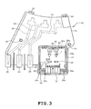
- FIG. 3 is a plan view of a terminal block assembly;
- FIG. 4 is a longitudinal sectional side view of the terminal block assembly;
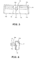
- FIG. 5 is a plan view of a sensor case; and
- FIG. 6 is a longitudinal sectional side view of the sensor case.
- The invention will be described in more detail with reference to the accompanying drawings. FIGS. 1 to 6 illustrate one embodiment in which the invention is applied to a DC brushless motor of the outer rotor type for driving a rotating tub of a washing machine, for example.
- Referring to FIGS. 1 and 2, the
motor 1 of the embodiment comprises astator 2 and a rotor 3. The rotor 3 includes aframe 4 made from a magnetic material into the shape of a shallow dish, anannular rotor core 5 disposed along an inner circumferential surface of a circumferential wall of theframe 4, and magnetic fieldpermanent magnets 6 disposed on the inner circumference of therotor core 5.Magnet insertion holes 7 are provided in the inner circumference of therotor core 5. The magnetic fieldpermanent magnets 6 are inserted in themagnet insertion holes 7 respectively. Therotor core 5, the magnetic fieldpermanent magnets 6 and theframe 4 are integrated by molded resin 8 (shown only in FIG. 2). On a central part of theframe 4 is provided aboss 9 to be coupled to an end of a rotating tub shaft which is not shown. - The
stator 2 includes astator core 11 having a number of radially extendingteeth 10, aninsulating cover 12 covering thestator core 11 and coils13 wound on portions of theinsulating cover 12 covering theteeth 10. Eachcoil 13 comprises threecoil wires 13a (shown only in FIG. 2). - The
stator core 11 is made by stacking a plurality of steel sheets. Theinsulating cover 12 is made from a non-conductive synthetic resin and comprises a pair of covering members sandwiching thestator core 11 from both axial sides. - A
terminal block 15 and aterminal block assembly 16 are attached to an end face (hereinafter, "upper end face") of both axial end faces of theinsulating cover 12 unopposed to theframe 4. Theterminal block 15 and theterminal block assembly 16 are provided so that ends of thecoil wires 13a are easily connected to an external circuit (not shown). A plurality of engagement portions (partially shown in FIG. 2) are provided on the upper end face of theinsulating cover 12. Furthermore, theterminal block 15 and theterminal block assembly 16 have engagedportions 18 respectively. The engagedportions 18 are engaged with theengagement portions 17 respectively so that theterminal block 15 and theterminal block assembly 16 are fixed to the insulatingcover 12. - Furthermore, six rectangular cylindrical housing portions 19 (only one being shown in FIG. 2) are formed integrally in the portion of the upper end face of the
insulating cover 12 to which portion theterminal block 15 and theterminal block assembly 16 are attached. Thehousing portions 19 are disposed along the inner circumference of theinsulating cover 12. One ends (terminal for external connection) of therespective coil wires 13a are inserted into three of the sixhousing portions 19 located under theterminal block 15. - The
terminal block 15 is made from non-conductive synthetic resin. Threehousing portions 20 are formed integrally in a lower face of the terminal block 15 (a face opposed to the insulating cover 12). A common connection conductive plate (not shown) is embedded in theterminal block 15. A connecting portion which is an end of the conductive plate protrudes into thehousings 20. When theterminal block 15 is attached to theinsulating cover 12, thehousing 20 is adapted to be fitted with the threehousings 19 located higher as viewed in FIG. 1, whereby the connecting portion and common connection terminal are electrically connected to each other. - Referring to FIGS. 3 and 4, the
terminal block assembly 16 includes aterminal block 21 comprising a non-conductive synthetic resin and acircuit board 22 provided integrally on theterminal block 21. Theterminal block 21 includes a portion located on theinsulating cover 12 and a portion protruding from theinsulating cover 12. Threehousing portions 23 are formed integrally in the underside of a portion of theterminal block 21 located on the insulating cover 12 (surface opposed to the insulating cover). - Three
conductive plates 24 for external connection are embedded in theterminal block 21. Theconductive plates 24 have respective one ends provided with connecting portions (not shown) projecting into thehousing portions 23. When theterminal block assembly 16 has been attached to theinsulating cover 12, thehousing portions 23 are adapted to be fitted with the threehousing portions 10 located lower as viewed FIG. 2, whereby the connecting portion and the external connection terminals are electrically connected together. - A rectangular
cylindrical connector 25 and aboard housing portion 27 are formed integrally on an outer circumferential upper surface of the portion of theterminal block 21 protruding from theinsulating cover 12. Theboard housing portion 27 is defined by a rectangularcylindrical housing wall 26. Theconductive plates 24 have the other ends located in theconnector 25. Accordingly, when a connector (not shown) of an external circuit is fitted into theconnector 25, the threeconductive plates 24 are connected to the external circuit. - Furthermore, a rectangular plate-
shaped circuit board 22 is housed in theboard housing portion 27. Thehousing wall 26 has an inner circumferential surface provided with a plurality ofclaws 26a engaging a circumferential edge of thecircuit board 22. Some of theclaws 26a engage one of sides of thecircuit board 22 and theother claws 26a engage the other side of thecircuit board 22. Thecircuit board 22 is fixed in theboard housing portion 27. - On the
circuit board 22 are provided a magnetism detecting circuit (not shown) comprising adiode 28, acapacitor 29,Hall elements 30 serving as a rotation sensor, and the like. Thediode 28 and thecapacitor 29 are provided on one side of thecircuit board 22 and have respectivelead wires circuit board 22. - Furthermore, a
connector 31 is provided on an end of one side of thecircuit board 22. An external connectionconductive plate 32 has one end protruding into theconnector 31. The other end of theconductive plate 32 is soldered to thecircuit board 22. Thehousing wall 26 is provided with amultiple wall 26b located at both sides of theconnector 31 when thecircuit board 22 is placed in thecircuit housing 27 and anopening 26c corresponding to an end of theconnector 31. - An element case 33 (serving as a sensor case) made from a resin is mounted on an end of the other side of the
circuit board 22 for the purpose of holding theHall elements 30. Theelement case 33 has two juxtaposedhousings 34 in which theHall elements 30 are adapted to be held therein as shown in FIGS. 5 and 6. TheHall elements 30 are provided for detecting a rotational position of the rotor 3. TheHall elements 30 havelead wires 30a soldered to thecircuit board 22. - The
element case 33 has a side which is opposed to openings of thehousings 34 and formed into agentle arc face 33a. Afitting protrusion 35 is provided integrally on a central part of the mounting face of theelement case 33 which is mounted oncircuit board 22. Thefitting protrusion 35 is inserted through a hole 36 (see FIG. 4) provided in thecircuit board 22 and comprises a pair of half-columns 35a which are disposed so as to become generally columnar. Thehole 36 has an inner diameter slightly smaller than an outer diameter of the wholefitting protrusion 35. Accordingly, theprotrusion 35 elastically deforms in such a direction that the half-columns 35a comes close thereto when inserted through thehole 36. Theprotrusion 35 inserted through thehole 36 is thus prevented from falling out of thehole 36. - Furthermore, an
engagement convexity 37 is provided on a central part of a side of theelement case 33 opposed to the mounting face of theelement case 33 which is mounted oncircuit board 22. Theboard housing 27 of theterminal block 22 has a bottom provided with ahole 38 corresponding to theengagement convexity 37. Theengagement convexity 37 is adapted to engage thehole 38 when thecircuit board 22 is placed in theboard housing 27. - Potting of
urethane 40 serving as a moisture-proof material is applied in theboard housing 27 to prevent thecircuit board 22 from being exposed. - An assembling procedure of the
terminal block assembly 16 will now be described. Firstly, theelement case 33 is mounted to thecircuit board 22 on which thediode 28, thecapacitor 29 and the like have been mounted. More specifically, thefitting protrusion 35 of theelement case 33 is fitted into thehole 36 of thecircuit board 22. TheHall elements 30 are then inserted into therespective housings 34 of theelement case 33. TheHall elements 30 having been inserted in therespective housings 34 are held by engaging means (not shown) so as to be prevented from falling out of thehousings 34. - Subsequently, the
circuit board 22 is placed in theboard housing 27 of theterminal block 21 with the board side with theelement case 33 being placed down so that the engagement convexity 3 engages thehole 38 of theboard housing 27. In this case, theelement case 33 is elastically deformed slightly such that thearc surface 33a comes to a planar shape and many parts of thearc surface 33a strongly abut against thehousing wall 26. FIG. 3 shows thearc surface 33a before elastic deformation. However, as shown in FIG. 4, even after the elastic deformation, a small gap is adapted to be defined between thearc surface 33a and thehousing wall 26. More specifically, in the embodiment, thearc surface 33a serves as an abutting surface, and thehousing wall 26 serves as a positioning wall. Furthermore, the positioning portion in the present invention is composed of thearc surface 33a and thehousing wall 26. As a result, theelement case 33 is fixed to theterminal block 21, and theHall elements 30 held by theelement case 33 are positioned relative to theterminal block 21. - Subsequently, the
board housing 27 is filled withurethane 40, which is then hardened. Thus, theterminal block assembly 16 is constructed. Theurethane 40 has low viscosity although relatively less expensive. Since themultiple wall 26b is provided in the embodiment, theurethane 40 can be prevented from leaking from theopening 26c. - According to the embodiment, the
board housing 27 is provided in the terminal block, and thecircuit board 22 having the magnetism detecting circuit is provided in theboard housing 27. Accordingly, the magnetism detecting circuit can be provided in theterminal block 21 more easily as compared with the conventional arrangement in which the conductive plate constituting the magnetism detecting circuit is embedded in the terminal block. - Furthermore, the
Hall elements 30 are held in theelement case 33 mounted on thecircuit board 22. Thecircuit board 22 is then placed in theboard housing 27, whereby theHall elements 30 are positioned relative to theterminal block 21. Moreover, theengagement convexity 37 provided on theelement case 33 is caused to engage thehole 38, and thearc surface 33a is caused to abut against thehousing wall 26 so that theelement case 33 is prevented from rattling, whereby theHall elements 33 are positioned. Consequently, theHall elements 30 can be positioned relative to theterminal block 21 easily and accurately. - Furthermore, the
element case 33 is provided with thefitting protrusion 35 which is fitted into thehole 36 so that theelement case 33 is fixed to thecircuit board 22. Consequently, the working efficiency can be improved when theelement case 33 is mounted on thecircuit board 22. - The present invention should not be limited to the foregoing embodiment but may be modified or expanded within a range not departing from the gist.
- As obvious from the foregoing, the motor of the present invention is useful as a motor for driving a rotating tub in a washing machine, for example, since the rotational position of the rotor can be controlled accurately.
Claims (4)
- An electric motor which comprises:a stator (2);a rotor (3) having a field permanent magnet (6);a terminal block (21) fixed to the stator (2); anda magnetism detecting circuit detecting magnetism of the field permanent magnet (6), thereby detecting a rotational position of the rotor (3), characterized in that:the magnetism detecting circuit includes a circuit board (22) provided in the terminal block (21) and a rotation sensor (30) which is attached to the circuit board (22) while being held by a sensor case (33); andthe sensor case (33) includes a positioning portion the rotation sensor (30) relative to the terminal block (21) when the circuit board (22) has been provided in the terminal block (21).
- The motor of claim 1, further comprising a positioning wall (26) provided on the terminal block (21) and an engagement hole (38), wherein the positioning portion is provided in the sensor case (33) and includes an engagement convexity (37) engaging the engagement hole (38) when the circuit board (22) has been provided in the terminal block (21), and an abutting surface (33a) abutting the wall (26).
- The motor of claim 1, further comprising a hole defined in the circuit board (22) and a fitting protrusion (35) provided on the sensor case (33), wherein the sensor case (33) is constructed so as to be fixed to the circuit board (22) when the fitting protrusion (35) is fitted in the hole (36).
- The motor of claim 1, further comprising a board housing (27) defined by a housing wall (26) in the terminal block (21), wherein the board housing (27) is filled with a moisture-proof material (40) after the circuit board (22) has been housed therein.
Applications Claiming Priority (2)
| Application Number | Priority Date | Filing Date | Title |
|---|---|---|---|
| JP2004150520A JP4496010B2 (en) | 2004-05-20 | 2004-05-20 | motor |
| PCT/JP2005/007150 WO2005114816A1 (en) | 2004-05-20 | 2005-04-13 | Motor |
Publications (2)
| Publication Number | Publication Date |
|---|---|
| EP1758228A1 true EP1758228A1 (en) | 2007-02-28 |
| EP1758228A4 EP1758228A4 (en) | 2009-01-14 |
Family
ID=35428645
Family Applications (1)
| Application Number | Title | Priority Date | Filing Date |
|---|---|---|---|
| EP05730558A Withdrawn EP1758228A4 (en) | 2004-05-20 | 2005-04-13 | Motor |
Country Status (7)
| Country | Link |
|---|---|
| US (1) | US7893578B2 (en) |
| EP (1) | EP1758228A4 (en) |
| JP (1) | JP4496010B2 (en) |
| KR (1) | KR20070012523A (en) |
| CN (1) | CN100527568C (en) |
| TW (1) | TW200607208A (en) |
| WO (1) | WO2005114816A1 (en) |
Cited By (6)
| Publication number | Priority date | Publication date | Assignee | Title |
|---|---|---|---|---|
| EP2182616A2 (en) | 2008-11-04 | 2010-05-05 | KNF Neuberger GmbH | Brushless DC motor |
| FR2942922A1 (en) * | 2009-03-05 | 2010-09-10 | Zhongshan Broad Ocean Motor Co | DEVICE FOR DETECTING THE POSITION OF A MOTOR ROTOR |
| EP2770619A2 (en) * | 2013-02-26 | 2014-08-27 | Yamaha Hatsudoki Kabushiki Kaisha | Rotating electric machine, engine, and vehicle |
| EP2824808A3 (en) * | 2013-07-08 | 2016-11-02 | Yamaha Hatsudoki Kabushiki Kaisha | Rotating electric machine and saddle-ride type vehicle |
| EP2375544A3 (en) * | 2010-04-09 | 2017-01-25 | Samsung Electronics Co., Ltd. | Motor for washing machine and washing machine having the same |
| EP3690294B1 (en) | 2017-09-27 | 2025-04-30 | Zhejiang Sanhua Intelligent Controls Co., Ltd. | ELECTRONIC EXPANSION VALVE |
Families Citing this family (37)
| Publication number | Priority date | Publication date | Assignee | Title |
|---|---|---|---|---|
| DE102005046759A1 (en) * | 2005-09-29 | 2007-04-05 | BSH Bosch und Siemens Hausgeräte GmbH | Connection plate may be L-shaped and consist of a receiver region with sensor in opening and having a depression for holding conductor plate |
| JP4789676B2 (en) * | 2006-03-29 | 2011-10-12 | トヨタ自動車株式会社 | Terminal module for rotating electric machine and rotating electric machine |
| JP2007300769A (en) * | 2006-05-08 | 2007-11-15 | Matsushita Electric Ind Co Ltd | motor |
| WO2007139129A1 (en) * | 2006-06-01 | 2007-12-06 | Panasonic Corporation | Brushless motor for washing machine and washing machine having the brushless motor mounted therein |
| JP4957191B2 (en) * | 2006-11-03 | 2012-06-20 | 株式会社デンソー | Motor driver and manufacturing method thereof |
| JP4044603B1 (en) * | 2007-02-14 | 2008-02-06 | 松下電器産業株式会社 | motor |
| DE102007045535B4 (en) * | 2007-09-24 | 2021-04-29 | Asm Automation Sensorik Messtechnik Gmbh | Angle sensor |
| DE102008043033A1 (en) * | 2008-10-22 | 2010-04-29 | Hilti Aktiengesellschaft | brush holder |
| CN101752973B (en) * | 2008-12-13 | 2013-07-17 | 中山大洋电机股份有限公司 | Direct-drive motor |
| KR101026083B1 (en) * | 2008-12-23 | 2011-03-31 | 주식회사 아모텍 | Slim stator and its manufacturing method |
| CN101814814B (en) * | 2009-02-24 | 2013-04-10 | 株式会社美姿把 | starter generator |
| JP5398348B2 (en) * | 2009-05-20 | 2014-01-29 | 株式会社東芝 | Permanent magnet motor and washing machine |
| US20120262015A1 (en) * | 2009-10-14 | 2012-10-18 | Daesung Electric Co., Ltd. | Resolver of electric driving motor for vehicle |
| JP5067676B2 (en) * | 2010-03-12 | 2012-11-07 | 株式会社デンソー | Sensor unit and magnetism collecting module |
| KR101130978B1 (en) * | 2010-06-23 | 2012-03-28 | 주식회사 아모텍 | Slim type stator and method of making the same, slim type motor having the stator, and direct drive apparatus for drum-washing machine |
| KR101197950B1 (en) * | 2011-04-13 | 2012-11-05 | 뉴모텍(주) | Fan motor |
| KR101243468B1 (en) * | 2011-08-17 | 2013-03-13 | 뉴모텍(주) | Stator Assembly with Magmate Holder |
| JP5818727B2 (en) * | 2012-03-21 | 2015-11-18 | 株式会社東芝 | motor |
| JP5889728B2 (en) | 2012-06-19 | 2016-03-22 | 愛三工業株式会社 | Stator components |
| JP5858364B2 (en) * | 2012-09-27 | 2016-02-10 | 澤藤電機株式会社 | Rotor for generator |
| JP6291292B2 (en) * | 2013-05-14 | 2018-03-14 | アスモ株式会社 | Rotating electric machine |
| WO2015037110A1 (en) * | 2013-09-12 | 2015-03-19 | 三菱電機株式会社 | Brushless dc motor and air conditioner using same |
| CN108539894B (en) * | 2013-09-17 | 2020-06-26 | 松下知识产权经营株式会社 | Brushless DC motor and blower device equipped with same |
| JP6221804B2 (en) * | 2014-02-13 | 2017-11-01 | トヨタ自動車株式会社 | Rotating electric machine stator |
| JP6261462B2 (en) * | 2014-06-27 | 2018-01-17 | ミネベアミツミ株式会社 | Resolver, its terminal block structure and motor rotation angle detection sensor |
| JP6441648B2 (en) * | 2014-11-14 | 2018-12-19 | 株式会社マキタ | Electric working machine |
| KR102522610B1 (en) * | 2015-12-08 | 2023-04-17 | 현대모비스 주식회사 | Motors for eco-friendly vehicle |
| WO2017154838A1 (en) | 2016-03-09 | 2017-09-14 | アスモ株式会社 | Motor and method for manufacturing motor |
| US10784753B2 (en) | 2017-06-01 | 2020-09-22 | Nsk Ltd. | Electric drive device and electric power steering device |
| TWI651919B (en) * | 2017-07-10 | 2019-02-21 | 建準電機工業股份有限公司 | Drive assembly for motor and semiconductor package structure for motor excitation |
| TWI651918B (en) * | 2017-07-10 | 2019-02-21 | Sunonwealth Electric Machine Industry Co., Ltd. | Semiconductor package structure and motor for motor drive |
| JP6922537B2 (en) * | 2017-08-08 | 2021-08-18 | 株式会社デンソー | Brushless motor |
| CN109713850A (en) * | 2017-10-25 | 2019-05-03 | 德昌电机(深圳)有限公司 | Electric machine assembly |
| JP6965710B2 (en) * | 2017-12-06 | 2021-11-10 | 日本電産トーソク株式会社 | Electric actuator |
| US11139722B2 (en) | 2018-03-02 | 2021-10-05 | Black & Decker Inc. | Motor having an external heat sink for a power tool |
| WO2021247954A1 (en) | 2020-06-05 | 2021-12-09 | Milwaukee Electric Tool Corporation | Brushless motor for a power tool |
| US12107468B2 (en) | 2020-12-23 | 2024-10-01 | Black & Decker Inc. | Brushless DC motor having high power density for power tool |
Family Cites Families (13)
| Publication number | Priority date | Publication date | Assignee | Title |
|---|---|---|---|---|
| FR2684760A1 (en) | 1991-12-06 | 1993-06-11 | Valeo Systemes Dessuyage | DEVICE FOR MEASURING THE INSTANTANEOUS ANGULAR POSITION OF A ROTATING PART, AND ELECTRODYNAMIC MACHINE EQUIPPED WITH SUCH A DEVICE. |
| US6348752B1 (en) * | 1992-04-06 | 2002-02-19 | General Electric Company | Integral motor and control |
| IT1255190B (en) * | 1992-06-30 | 1995-10-20 | Giuseppe Marchisi | CONTROL INTERFACE DEVICE FOR AN ELECTRIC MOTOR |
| JP3497684B2 (en) * | 1996-03-19 | 2004-02-16 | 株式会社東芝 | Rotating electric machine stator |
| JPH09318305A (en) * | 1996-05-31 | 1997-12-12 | Denso Corp | Position detection device |
| JP3545215B2 (en) * | 1998-07-21 | 2004-07-21 | 愛知電機株式会社 | Brushless motor |
| US6050785A (en) | 1998-11-04 | 2000-04-18 | Sunonwealth Electric Machine Industry Co., Ltd. | Axle balance plates for miniature heat dissipating fan assemblies |
| FR2805121B1 (en) * | 2000-02-11 | 2002-04-26 | Leroy Somer | MODULAR CONVERTER |
| US6488475B2 (en) * | 2000-03-30 | 2002-12-03 | Matsushita Electric Industrial Co., Ltd. | Electric blower and electric cleaner with an air cooled power device situated between the impeller and motor |
| JP4071484B2 (en) * | 2000-12-22 | 2008-04-02 | 株式会社ミツバ | Motor equipment |
| JP3638269B2 (en) * | 2002-03-14 | 2005-04-13 | 三菱電機株式会社 | Electric power steering device |
| JP3894853B2 (en) * | 2002-07-11 | 2007-03-22 | 株式会社日本自動車部品総合研究所 | Rotating machine |
| JP4073759B2 (en) * | 2002-11-07 | 2008-04-09 | 三菱電機株式会社 | Rotating electric machine for vehicles |
-
2004
- 2004-05-20 JP JP2004150520A patent/JP4496010B2/en not_active Expired - Fee Related
-
2005
- 2005-04-13 KR KR1020067025210A patent/KR20070012523A/en not_active Ceased
- 2005-04-13 US US11/596,970 patent/US7893578B2/en not_active Expired - Fee Related
- 2005-04-13 EP EP05730558A patent/EP1758228A4/en not_active Withdrawn
- 2005-04-13 WO PCT/JP2005/007150 patent/WO2005114816A1/en not_active Ceased
- 2005-04-13 CN CNB2005800161178A patent/CN100527568C/en not_active Expired - Fee Related
- 2005-05-12 TW TW094115400A patent/TW200607208A/en not_active IP Right Cessation
Cited By (10)
| Publication number | Priority date | Publication date | Assignee | Title |
|---|---|---|---|---|
| EP2182616A2 (en) | 2008-11-04 | 2010-05-05 | KNF Neuberger GmbH | Brushless DC motor |
| DE102008055731A1 (en) * | 2008-11-04 | 2010-05-12 | Knf Neuberger Gmbh | Brushless DC motor |
| US8466590B2 (en) | 2008-11-04 | 2013-06-18 | Knf Neuberger Gmbh | Plug-in sensor board for brushless direct current motor |
| DE102008055731B4 (en) * | 2008-11-04 | 2014-07-31 | Knf Neuberger Gmbh | Brushless DC motor |
| FR2942922A1 (en) * | 2009-03-05 | 2010-09-10 | Zhongshan Broad Ocean Motor Co | DEVICE FOR DETECTING THE POSITION OF A MOTOR ROTOR |
| US9735652B2 (en) | 2010-04-08 | 2017-08-15 | Samsung Electronics Co., Ltd. | Motor for washing machine and washing machine having the same |
| EP2375544A3 (en) * | 2010-04-09 | 2017-01-25 | Samsung Electronics Co., Ltd. | Motor for washing machine and washing machine having the same |
| EP2770619A2 (en) * | 2013-02-26 | 2014-08-27 | Yamaha Hatsudoki Kabushiki Kaisha | Rotating electric machine, engine, and vehicle |
| EP2824808A3 (en) * | 2013-07-08 | 2016-11-02 | Yamaha Hatsudoki Kabushiki Kaisha | Rotating electric machine and saddle-ride type vehicle |
| EP3690294B1 (en) | 2017-09-27 | 2025-04-30 | Zhejiang Sanhua Intelligent Controls Co., Ltd. | ELECTRONIC EXPANSION VALVE |
Also Published As
| Publication number | Publication date |
|---|---|
| CN1957517A (en) | 2007-05-02 |
| US20070252454A1 (en) | 2007-11-01 |
| EP1758228A4 (en) | 2009-01-14 |
| KR20070012523A (en) | 2007-01-25 |
| TWI301687B (en) | 2008-10-01 |
| JP4496010B2 (en) | 2010-07-07 |
| JP2005333741A (en) | 2005-12-02 |
| TW200607208A (en) | 2006-02-16 |
| WO2005114816A1 (en) | 2005-12-01 |
| US7893578B2 (en) | 2011-02-22 |
| CN100527568C (en) | 2009-08-12 |
Similar Documents
| Publication | Publication Date | Title |
|---|---|---|
| US7893578B2 (en) | Electric motor with discrete circuit board and sensor case | |
| US4934041A (en) | Method of assembling brushless electric motors | |
| CN104205584B (en) | Motor | |
| CN104380582B (en) | For installing method and the structure of the sensor base plate of brushless electric machine | |
| CN108781019A (en) | Motor and be used for method manufacturing of electric machines | |
| EP4113794A1 (en) | Motor | |
| US10958124B2 (en) | Motor | |
| CN112640264A (en) | Motor | |
| US20130002070A1 (en) | Motor | |
| JP4434885B2 (en) | motor | |
| US20110198952A1 (en) | Brushless dc motor | |
| KR20170045998A (en) | Rotor assembly and motor having the same | |
| KR102858758B1 (en) | Rotor and motor having the same | |
| CN112689943B (en) | Motor | |
| JP7239333B2 (en) | motor | |
| US20130002069A1 (en) | Motor | |
| CN113454887B (en) | Basic body for electric motors | |
| KR20210109272A (en) | Rotor and motor having the same | |
| US20240055956A1 (en) | Brushless electric motor | |
| KR20190072894A (en) | Rotor and Motor having the same | |
| KR20190073880A (en) | Stator and motor having the same | |
| JPH09275666A (en) | Method for manufacturing coil of flat facing type brushless motor | |
| KR20220086181A (en) | Rotor and motor having the same | |
| KR20190090930A (en) | Sensing stator and motor having the same | |
| CN115667687A (en) | Electric control throttle device |
Legal Events
| Date | Code | Title | Description |
|---|---|---|---|
| PUAI | Public reference made under article 153(3) epc to a published international application that has entered the european phase |
Free format text: ORIGINAL CODE: 0009012 |
|
| 17P | Request for examination filed |
Effective date: 20061213 |
|
| AK | Designated contracting states |
Kind code of ref document: A1 Designated state(s): DE GB |
|
| DAX | Request for extension of the european patent (deleted) | ||
| RBV | Designated contracting states (corrected) |
Designated state(s): DE GB |
|
| A4 | Supplementary search report drawn up and despatched |
Effective date: 20081211 |
|
| 17Q | First examination report despatched |
Effective date: 20100605 |
|
| STAA | Information on the status of an ep patent application or granted ep patent |
Free format text: STATUS: THE APPLICATION IS DEEMED TO BE WITHDRAWN |
|
| 18D | Application deemed to be withdrawn |
Effective date: 20141101 |