EP1761696B1 - Procede et systeme pour mettre a disposition un signal de phase ameliore provenant d'un detecteur de phase installe sur un arbre a cames d'un moteur a combustion interne - Google Patents
Procede et systeme pour mettre a disposition un signal de phase ameliore provenant d'un detecteur de phase installe sur un arbre a cames d'un moteur a combustion interne Download PDFInfo
- Publication number
- EP1761696B1 EP1761696B1 EP04740123A EP04740123A EP1761696B1 EP 1761696 B1 EP1761696 B1 EP 1761696B1 EP 04740123 A EP04740123 A EP 04740123A EP 04740123 A EP04740123 A EP 04740123A EP 1761696 B1 EP1761696 B1 EP 1761696B1
- Authority
- EP
- European Patent Office
- Prior art keywords
- signal
- phase
- phase sensor
- internal combustion
- sensor
- Prior art date
- Legal status (The legal status is an assumption and is not a legal conclusion. Google has not performed a legal analysis and makes no representation as to the accuracy of the status listed.)
- Expired - Lifetime
Links
- 238000000034 method Methods 0.000 title claims description 54
- 238000002485 combustion reaction Methods 0.000 title claims description 53
- 230000006978 adaptation Effects 0.000 claims description 35
- 230000008569 process Effects 0.000 claims description 24
- 230000006399 behavior Effects 0.000 claims description 7
- 230000006870 function Effects 0.000 claims description 5
- 238000004590 computer program Methods 0.000 claims description 3
- 230000008859 change Effects 0.000 description 11
- 238000012935 Averaging Methods 0.000 description 5
- 238000002347 injection Methods 0.000 description 5
- 239000007924 injection Substances 0.000 description 5
- 238000009434 installation Methods 0.000 description 4
- 230000001419 dependent effect Effects 0.000 description 3
- 230000008901 benefit Effects 0.000 description 2
- 238000004364 calculation method Methods 0.000 description 2
- RDYMFSUJUZBWLH-UHFFFAOYSA-N endosulfan Chemical compound C12COS(=O)OCC2C2(Cl)C(Cl)=C(Cl)C1(Cl)C2(Cl)Cl RDYMFSUJUZBWLH-UHFFFAOYSA-N 0.000 description 2
- 230000002349 favourable effect Effects 0.000 description 2
- 238000012417 linear regression Methods 0.000 description 2
- 230000007246 mechanism Effects 0.000 description 2
- 230000009897 systematic effect Effects 0.000 description 2
- 108010076504 Protein Sorting Signals Proteins 0.000 description 1
- 230000009471 action Effects 0.000 description 1
- 230000004913 activation Effects 0.000 description 1
- 230000008021 deposition Effects 0.000 description 1
- 238000006073 displacement reaction Methods 0.000 description 1
- 239000000446 fuel Substances 0.000 description 1
- 230000001939 inductive effect Effects 0.000 description 1
- 238000013507 mapping Methods 0.000 description 1
- 230000001360 synchronised effect Effects 0.000 description 1
Images


Definitions
- the invention relates to a method for providing an improved phase signal of a phase sensor on a camshaft of an internal combustion engine immediately after switching on the phase sensor and / or the internal combustion engine.
- the phase sensor scans angle marks of a donor wheel rotatably connected to the camshaft.
- a crankshaft sensor scans angle marks of a donor wheel rotatably connected to the crankshaft.
- crankshaft and camshaft are each connected to a disc on the surface thereof at least one reference mark is attached, wherein on the crankshaft pulley in addition a plurality of similar markings, also called increments, are mounted.
- the two rotating discs are scanned by fixed sensors. From the time sequence of the signals supplied by the sensors in the form of pulses can be a clear statement about the position of crankshaft and camshaft win and it can be formed in the engine control corresponding control signals for the injection or ignition.
- the correction values are immediately available when the internal combustion engine is restarted. in principle the requirements for an accurate signal of the phase sensor, especially when starting the internal combustion engine increase.
- a precise angular position of the phase signal to the crankshaft signal immediately after starting the internal combustion engine leads to a better and optimized control of the injection, ignition and Nockenwellenverstellsystemen, which ultimately leads to a better emission behavior of the internal combustion engine in startup mode.
- the deviation of the startup signal position of the crankshaft signal-based phase signal from the normal signal position is based in particular on the following parameters: air gap between the sender wheel on the camshaft and the phase sensor, temperature and rotational speed of the camshaft / crankshaft.
- a particularly large influence thereby contributes to the air gap, which depends on the installation conditions and may be different from internal combustion engine to internal combustion engine.
- the influence of the air gap can be corrected in particular when the phase sensor or the internal combustion engine is switched on again.
- the method is carried out in particular when the crankshaft and the camshaft are synchronized.
- the correction of the phase signal according to step b.1) takes place in such a way that the corrected phase signal during the calibration procedure on the basis of the crankshaft signal results in a corrected start-up signal position, which substantially corresponds to the normal signal position.
- the calibration procedure or the adaptation during the calibration process is not one of the engine control outgoing active action.
- the engine control can not influence this "adaptation".
- the change in the signal position of the phase signal depends exclusively on the calibration process taking place in the phase sensor.
- the desired signal position or normal signal position according to step a.1) is reached when the phase signal is based on a switching threshold of the phase sensor which lies in the range of a specific percentage of the maximum signal detected by the phase sensor.
- the phase sensor used has a switch-on switching threshold, which is at a comparatively low input signal of the sensor. This is therefore necessary to allow for immediate switching of sensors after switching on, in which a comparatively large air gap between the sensor and the angle mark of the encoder wheel is present. Since the air gap may vary depending on the installation, it is provided that the phase sensor calibrates itself. In this case, the switching threshold is gradually shifted in a range dependent on the maximum input signal deviation of the sensor.
- the preset switching threshold of the sensor is shifted stepwise to a value of in particular approximately 70% of the maximum detected value. If the switching threshold reaches the predetermined value, the desired signal position or the normal signal position is reached. The calibration process is then completed. The duration of the calibration process depends on the size of the air gap.
- the calibration process takes place during the startup of the internal combustion engine.
- the start of the internal combustion engine is advantageously completed after eight working games.
- the calibration process is then advantageously completed at the latest also after eight working games; However, it can also be completed beforehand, depending on the size of the air gap. This ensures that the startup signal position is brought in small steps to the normal signal position, whereby unwanted, too large signal deviations are avoided. This results in a stable and systematic behavior.
- a method according to the invention can be distinguished by the fact that the correction values are formed from a maximum angle error in the case of the first scanned angle mark and of further angle errors corrected by the adaptation values in the case of further scanned angle marks.
- the correction values can correspond to the respective angle errors.
- the correction values may also be values dependent on the angle errors, for example values corrected for temperature or rotational speed.
- characteristic values can also be used for the angle errors; for example, it is conceivable to use a straight line based on the angle errors or approximated to the angle errors.
- a method according to the invention may be distinguished by the fact that, when the phase sensor or the internal combustion engine is switched on a number of times after step b.1), the corrected startup signal position is compared with the expected startup signal position based on the previously stored correction values, and a repeated one Averaging, in particular a moving averaging, which takes place according to step a.4) correction values.
- the correction values therefore become saved, adapted and learned.
- the correction values to be used when the phase sensor or the internal combustion engine is switched on again are consequently optimized by the respective averaging.
- the angle marks on the encoder wheel of the camshaft may be formed as flanks of segments for generating high and low-phase signals.
- four segments are provided, each having a positive and a negative edge.
- the adaptation between two flanks can be limited to a maximum value, this maximum value in particular in the range of ⁇ 2 ° and ⁇ 0.1 °, and in particular in the range of ⁇ 0.2 ° to ⁇ 0.75 °, and especially in the range of ⁇ 0.25 °. Especially the range of ⁇ 0.25 ° has been found to be particularly advantageous. If a difference of the starting flank position to the normal flank position of, for example, 2.5 ° to be corrected at the camshaft, this is preferably done over ten to fourteen negative or positive edge change with a maximum adaptation of 0.25 ° between two edge changes. Typically, pro Working cycle provided a total of four negative edge changes; An adaptation then takes place over three to four working cycles.
- the deposition of the correction values in a non-volatile memory can be done in particular in the engine control.
- the nonvolatile memory may be, for example, a continuous RAM memory, in particular an EEPROM or a flash memory.
- a further, preferred embodiment of the invention is characterized in that the correction values are imaged by a straight line approximated to the angle errors.
- the straight line can be defined for example via a linear regression or over two selected value pairs. In this respect, it is sufficient to keep only the two defined values in the non-volatile memory.
- additional mechanisms can be used which, for example, check permissible ranges of the values.
- the adaptation and correction takes place under defined conditions of the camshaft. With a camshaft adjustment, this adjustment is taken into account. Furthermore, the adaptation takes place only if there are no detectable system disorders.
- Another embodiment of the invention is characterized in that a comparison of the determined angle errors or correction values is compared with the behavior typical of the phase encoder for the different air gaps. About a correlation of Both values can be used to determine the air gap to be found on the respective engine specimen. In addition, further air gap dependencies can be compensated. Furthermore, corresponding diagnostic and / or correction functions are set up or supported from this. As a result, due to the angular errors or the correction values, for example, it can be deduced that the air gap is too large and that corresponding instructions are given, for example, at the end of the tape or in the workshop about improper installation.
- the invention also relates to a system for carrying out the method according to the invention, to a motor controller for carrying out the method according to the invention and to a computer program for such a motor controller.
- FIG. 1 are shown in a rough overview, the most essential elements of the present invention in connection with an internal combustion engine including a motor control.
- an arrangement is already known in principle ( DE 43 10 460 A1 ).
- FIG. 1 is denoted by a donor gear 10 that is rigidly connected to the crankshaft 11 of the internal combustion engine and has a plurality of similar angle marks 12 at its periphery.
- a reference mark 13 is provided, which is formed for example by two missing angle marks. Usually a total of 60-2 angle marks over the entire circumference of 360 ° are provided.
- a second sender wheel 14 is connected to the camshaft 15 of the internal combustion engine and has at its periphery segments of different lengths, the shorter segments being denoted by 17 and the longer segments by 16. Interspaces are provided between the angle marks or segments, the longer ones carry the reference numeral 18, the shorter ones the reference symbol 19.
- Each segment 16, 17 is delimited by a positive flank 20 and a negative flank 21.
- the number of segments 16, 17 is selected so that a unique synchronization within each segment together with the reference signal on the crankshaft allowed.
- This arrangement is used for internal combustion engines with 4, 5, 6, 8 or more cylinders.
- the exact arrangement of the angle marks and the assignment of the segments 16, 17 to the brands of the encoder wheel 10 of the crankshaft 11 is to be made so that the in FIG. 2 signal sequences are obtained.
- the sender wheel 10 of the crankshaft 11 is detected by a crankshaft sensor 22; the sensor wheel 14 of the camshaft 15 from a phase sensor 23.
- the sensor 22 is, for example, an inductive pick-up or Hall sensors that generate signals as the angle marks pass in the sensors.
- the sensor 23 is an active sensor, e.g. a Hall sensor having the calibration behavior described above. The generated signals are supplied to the motor controller 24 and further processed there.
- the engine control 24 receives via the inputs 25, 26 and 27 further, required for the control of the engine input variables, which are supplied by suitable sensors. On the output side, the engine control 24 signals for the ignition, injection and camshaft control for unspecified Components of the internal combustion engine available; the outputs of the motor controller 24 are designated 28 and 29.
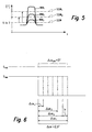
- FIG. 2 are the signals supplied by the sensors 22 and 23 and already processed into square-wave signals, which are evaluated in the engine control 24, above the crankshaft angle ( FIG. 2b) or the camshaft angle ( Figure 2c ) or over the time t ( FIG. 2f ) applied.
- the camshaft is driven at half the crankshaft speed of the crankshaft.
- crankshaft signal S KW supplied and processed by the crankshaft sensor 22 is plotted.
- the number of angle marks is 60-2;
- the missing two angle marks form the reference or reference mark 13. Since a working cycle of the internal combustion engine extends over two crankshaft revolutions, 60-2 pulses must be generated by the crankshaft encoder via a working cycle with the selected arrangement twice.
- FIG. 2b is the angle of rotation of the crankshaft over a working cycle, that is from 0 ° to 720, shown.
- FIG. 2d the waveform of the camshaft S NW is shown for a 4-cylinder internal combustion engine.
- the encoder wheel 14 of the camshaft 15 provides two different segments 17, 18 which lead in the signal to different low and high phases. Because both the Crankshaft signal and the camshaft signal are evaluated, the same segments can be distinguished by the existing or non-existent reference mark 13 in the encoder wheel 10 of the crankshaft 11.
- edge changes nFW resulting from the negative flanks 21 are shown on the sender wheel 14 of the camshaft 15 via a working cycle.
- Overall result per cycle four edge changes that have an equidistant angular distance of 90 ° to each other.
- an inaccurate signal S NW on the camshaft is initially given between the phase sensor 23 and the segments 16, 17, in particular due to a varying installation-related air gap.
- the starting signal position of the phase signal is adapted to the crankshaft signal in a normal signal position via a calibration of a maximum of sixty-four edges of the phaser 14, so a total of more than eight cycles in a 4-cylinder engine.
- the adaptation takes place in particular by changing the switching threshold of the phase sensor when detecting the edge change.
- Such a change in the switching threshold is exemplary in the FIG. 5 shown.
- the analog input signal of the phase sensor is plotted in Tesla over the time axis.
- a different angle mark signal WM For example, three different angle mark signals WM 1 , WM 2 and WM 3 are shown.
- the comparatively strong signal WM 1 results from a comparatively small air gap.
- the signal WM 2 the air gap is larger.
- the signal WM 3 the air gap is even greater; this signal is consequently weakest.
- the switching threshold SSW of the phase sensor is set comparatively low, a typical value is about 5 mTeslar above the signal offset.
- the preset switching threshold SSW is gradually shifted by the phase sensor to a value of approximately 70% of the maximum detected signal. According to FIG. 5 takes place at a signal W 1 is a displacement of the preset switching threshold SSW to for this signal MW 1 optimal switching threshold SSW. 1 In the case of an input signal WM 2 , the preset switching threshold SSW is shifted to the value of the nominal switching threshold SSW 2 .
- the adaptation of the preset value SSW to the respective particular air-gap-dependent value SSW 1, 2,... Takes place in small steps by angle values (adaptation values) jo, depending on the calibration behavior of the phase sensor, until the envisaged switching threshold is reached. Then there is the normal signal position of the camshaft signal to the crankshaft signal.
- the specification of the adaptation step size is defined in particular by the permissible shift level shift. This then results in an adaptation increment on an angle basis, depending on the respective LS.
- the adaptation takes place under certain boundary conditions, for example with a camshaft adjustment in late position. Before the adaptation, a Temperature correction based on characteristics stored in the control unit.
- FIG. 2d is the normal signal position of the signal S NW on the camshaft shown as a solid line.
- FIG. 2f represents the time axis t.
- the internal combustion engine is started at the time to.
- the phase sensor detects a negative edge change taking into account an angle error ⁇ .
- the calibration behavior of the phase sensor is plotted against the number of edge changes nFW in the calibration phase by the angle error ⁇ of the startup signal position deviating from the normal signal position.
- the startup signal position is gradually adjusted by a value ⁇ at each edge change due to the sensor calibration, until finally the normal signal position is reached.
- the difference between the starting signal position and the normal signal position, and thus the angular error ⁇ to be adapted depends on the size of the air gap between the phaser wheel and the camshaft phase sensor.
- FIG. 3 For example, a total of six adaptation curves of the angle errors .DELTA..alpha. are plotted as examples for air gaps of different sizes.
- the course along the line 40 results at an air gap of 0.1 mm; the course of the line 41 at an air gap of 0.8 mm; the course of the line 42 at an air gap of 1.5 mm; the course of the line 43 at an air gap of 2.2 mm; the course of the line 44 at an air gap of 2.0 mm and the course of the line 45 at an air gap of 1.8 mm.
- the angle error is adapted over a total of approximately 13 edge changes along the line 41.
- the adaptation course along the line 41 according to FIG. 3 and 4 applies to the first switching on of the phase sensor or the internal combustion engine.
- An initial switch-on may then be present: When the internal combustion engine is started for the first time, when the non-volatile memory is extinguished, when the phase sensor is installed or replaced, when the engine control unit is replaced, when all the functions in the engine control unit are reset.
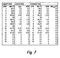
- the NW 57 °.
- the angle errors ⁇ 1 to ⁇ 13 can then be determined by comparing the start signal position with the normal signal position at the respective edge changes nFW. Corresponding values are the Fig. 7 refer to.
- the associated correction values KOW, which according to a first Embodiment of the invention, the angle errors ⁇ 1 to ⁇ 13 are stored in the non-volatile memory.
- phase signals are not only adapted by the adaptation values ⁇ but are additionally corrected by the correction values KOW stored in the memory in such a way that after the phase sensor or the internal combustion engine is switched on again, an improved phase signal is available, and in particular after re-switching at least largely the normal signal position is reached.
- the thus adapted and corrected start-up signal position of the phase signal to the crankshaft signal is compared with the repeated repeated start with the normal signal position.
- a new correction can be performed.
- the resulting new correction values can be used in a renewed starting of the internal combustion engine for the correction of the previously determined correction values are used.
- an improved, corrected start-up phase signal results in the case of several restarting processes.
- the correction of the phase signal is thus improved and learned by repeatedly repeating the adaptation and correction at power-up; In particular, a moving averaging is performed.
- the correction can be made by using correction values characteristic of the angle errors. This can be done, in particular, by mapping the correction values by a straight line approximating the angle errors. When an angle error of 2.5 ° occurs, the straight line then corresponds to the signal curve 41 of FIG. 3 , between flank changes two and twelve.
- the straight line can be calculated using a linear regression or two selected points. Thus it may suffice to keep only the selected values in the non-volatile memory and not fourteen or more individual correction values KOW.
Landscapes
- Combined Controls Of Internal Combustion Engines (AREA)
Claims (20)
- Procédé pour faire délivrer un signal de phase amélioré par un détecteur actif de phase (23) d'un arbre à cames (15) d'un moteur à combustion interne immédiatement après le branchement du détecteur de phase et/ou du moteur à combustion interne,
le détecteur de phase (23) détectant des repères d'angle (16, 17) d'une roue émettrice (14) reliée à rotation solidaire à l'arbre à cames (15) et exécutant une opération d'étalonnage pendant le démarrage du moteur à combustion interne,
un détecteur (22) de vilebrequin détectant des repères d'angle (12, 13) d'une roue émettrice (10) reliée à rotation solidaire au vilebrequin (11),
caractérisé par les étapes suivantes :a) après le premier branchement du détecteur de phase (23) :a.1) détermination de la position au démarrage du signal de phase (SNW) pendant l'opération d'étalonnage du détecteur de phase, sur base du signal (SKW) de vilebrequin et par l'intermédiaire de plusieurs repères d'angle (16, 17) de la roue émettrice (14) de l'arbre à cames (15), le signal de phase étant corrigé pas-à-pas par des valeurs d'adaptation (χi) pendant l'étape d'étalonnage du détecteur de phase jusqu'à ce que la position normale du signal soit atteinte,a.2) détermination de la position normale du signal de phase sur base du signal de vilebrequin (SKW) après le démarrage et lorsque l'opération d'étalonnage est terminée,a.3) détermination d'erreurs d'angle (Δαi) à partir de la différence entre la position du signal au démarrage et la position normale du signal eta.4) placement de valeurs de correction (KOW) basées sur les erreurs d'angle dans une mémoire non volatile etb) lors d'un nouveau branchement du détecteur de phase ou du moteur à combustion interne :b.1) correction du signal de phase (SNW) pendant l'étape d'étalonnage par les valeurs de correction (KOW) de telle sorte qu'après le nouveau branchement du détecteur de phase, on dispose d'un signal de phase (SNW-KROR, KWNWKOR) amélioré. - Procédé selon la revendication 1, caractérisé en ce que la correction du signal de phase (SNW) de l'étape b.1) s'effectue par le fait que pendant l'opération d'étalonnage, le signal de phase corrigé (SNW-KROR) délivre sur base du signal de vilebrequin une position de démarrage corrigée du signal (41') qui correspond essentiellement à la position normale du signal.
- Procédé selon les revendications 1. ou 2,
caractérisé en ce que la position normale du signal de l'étape a.1) est atteinte lorsque la phase d'étalonnage qui se déroule dans le détecteur de phase est terminée. - Procédé selon la revendication 3, caractérisé en ce que pendant la phase d'étalonnage, le seuil de commutation est suivi dans le détecteur de phase en fonction du signal détecté de telle sorte que le seuil de commutation (SSW) soit situé à un pourcentage défini de la course maximale du signal (WM) détecté par le détecteur de phase.
- Procédé selon les revendications 1, 2, 3 ou 4,
caractérisé en ce que les valeurs de correction sont formées d'une erreur maximale d'angle (Δα) sur le premier repère d'angle palpé et des autres erreurs d'angle (Δα1, Δα2, Δα3, ..., Δαn) corrigées des valeurs d'adaptation (χ) sur les autres repères d'angle palpés. - Procédé selon l'une des revendications précédentes, caractérisé en ce que lorsque le détecteur de phase ou le moteur à combustion interne sont branchés plusieurs fois après l'étape b.1), la position corrigée du signal au démarrage est comparée à la position attendue du signal au démarrage qui repose sur les valeurs de correction déjà conservées en mémoire et en ce qu'en cas de répétitions multiples, une valeur moyenne et en particulier une valeur moyenne glissante est formée en fonction des valeurs de correction qui sont conservées à l'étape a.4).
- Procédé selon l'une des revendications précédentes, caractérisé en ce que le démarrage s'effectue par plusieurs courses de travail du moteur à combustion interne et en ce que l'étape d'étalonnage est terminée complètement après au plus 8 courses de travail.
- Procédé selon l'une des revendications précédentes, caractérisé en ce que l'adaptation pas-à-pas entre deux repères d'angle voisins à l'étape a.1) est limitée à une valeur maximale d'adaptation (γ), cette valeur maximale d'adaptation étant comprise en particulier dans la plage de ± 2° à ± 0,1°, en particulier dans la plage de ± 0,2° et ± 0,75° et en particulier autour de ± 0,25°.
- Procédé selon l'une des revendications précédentes, caractérisé en ce que les valeurs de correction sont conservées dans une mémoire non volatile de la commande du moteur à combustion interne et/ou dans une mémoire non volatile du détecteur de phase.
- Procédé selon l'une des revendications précédentes, caractérisé en ce que les valeurs de correction sont formées par une droite qui approche les erreurs d'angle.
- Procédé selon l'une des revendications précédentes, caractérisé en ce que l'adaptation s'effectue autour des valeurs d'adaptation (χ) de l'étape a.1) et/ou de la correction de l'étape b.1) dans des conditions définies de l'arbre à cames.
- Procédé selon l'une des revendications précédentes, caractérisé en ce que l'effet de la dépendance vis-à-vis de l'entrefer et/ou vis-à-vis de la taille de l'entrefer entre le détecteur de phase et les repères d'angle est déterminé à partir des erreurs d'angle déterminées et des valeurs de correction ainsi que du comportement typique connu de l'émetteur de phase pour différents entrefers et en ce que des fonctions de diagnostic et/ou de correction qui y correspondent sont ainsi définies.
- Procédé selon l'une des revendications précédentes, caractérisé en ce que le détecteur de phase est réalisé par la technologie Hall ou la technologie magnéto-résistive (MR, GMR).
- Système qui délivre un signal amélioré d'un détecteur de phase qui détecte la position angulaire de l'arbre à cames d'un moteur à combustion interne immédiatement après le branchement du détecteur de phase et/ou du moteur à combustion interne et qui convient pour exécuter le procédé selon l'une des revendications précédentes, comprenant une roue émettrice reliée à rotation solidaire à l'arbre à cames, un détecteur de phase qui détecte la position de rotation de la roue émettrice, une roue de vilebrequin reliée à rotation solidaire au vilebrequin, un détecteur de vilebrequin qui détecte la position de rotation de la roue de vilebrequin, une commande de moteur qui traite les signaux du détecteur de phase et du détecteur de vilebrequin et une mémoire non volatile prévue pour conserver les valeurs de correction.
- Système selon la revendication 14, caractérisé en ce que la mémoire non volatile est une mémoire RAM permanente, en particulier une mémoire EEPROM ou une mémoire flash.
- Système selon les revendications 14 ou 15,
caractérisé en ce que la mémoire non volatile est disposée dans la commande du moteur. - Système selon les revendications 14, 15 ou 16,
caractérisé en ce que des lignes caractéristiques des valeurs de correction sont conservées ou peuvent être conservées dans la mémoire volatile et/ou dans la commande du moteur. - Commande pour un moteur à combustion interne,
caractérisée en ce qu'elle est configurée en vue d'exécuter le procédé selon l'une des revendications 1 à 13. - Programme informatique doté d'un code de programme pour une commande de moteur selon la revendication 18 ou un système selon l'une des revendications 14 à 17,
caractérisé en ce que la code de programme est configuré pour exécuter le procédé selon l'une des revendications 1 à 13. - Programme informatique selon la revendication 19,
caractérisé en ce que le code de programme est conservé sur un support de données lisible par ordinateur.
Priority Applications (1)
| Application Number | Priority Date | Filing Date | Title |
|---|---|---|---|
| EP04740123A EP1761696B1 (fr) | 2004-05-27 | 2004-06-21 | Procede et systeme pour mettre a disposition un signal de phase ameliore provenant d'un detecteur de phase installe sur un arbre a cames d'un moteur a combustion interne |
Applications Claiming Priority (4)
| Application Number | Priority Date | Filing Date | Title |
|---|---|---|---|
| EP2004005747 | 2004-05-27 | ||
| EP2004006554 | 2004-06-17 | ||
| EP04740123A EP1761696B1 (fr) | 2004-05-27 | 2004-06-21 | Procede et systeme pour mettre a disposition un signal de phase ameliore provenant d'un detecteur de phase installe sur un arbre a cames d'un moteur a combustion interne |
| PCT/EP2004/006686 WO2005119041A1 (fr) | 2004-05-27 | 2004-06-21 | Procede et systeme pour mettre a disposition un signal de phase ameliore provenant d'un detecteur de phase installe sur un arbre a cames d'un moteur a combustion interne |
Publications (2)
| Publication Number | Publication Date |
|---|---|
| EP1761696A1 EP1761696A1 (fr) | 2007-03-14 |
| EP1761696B1 true EP1761696B1 (fr) | 2010-01-20 |
Family
ID=37704350
Family Applications (1)
| Application Number | Title | Priority Date | Filing Date |
|---|---|---|---|
| EP04740123A Expired - Lifetime EP1761696B1 (fr) | 2004-05-27 | 2004-06-21 | Procede et systeme pour mettre a disposition un signal de phase ameliore provenant d'un detecteur de phase installe sur un arbre a cames d'un moteur a combustion interne |
Country Status (1)
| Country | Link |
|---|---|
| EP (1) | EP1761696B1 (fr) |
Cited By (2)
| Publication number | Priority date | Publication date | Assignee | Title |
|---|---|---|---|---|
| CN104234768A (zh) * | 2013-06-11 | 2014-12-24 | 罗伯特·博世有限公司 | 凸轮轴位置传感轮以及用于求取凸轮轴位置的方法和装置 |
| DE102016208711A1 (de) * | 2016-05-20 | 2017-11-23 | Robert Bosch Gmbh | Verfahren zum Bestimmen eines aktuellen Nockenwellenwinkels einer Nockenwelle einer Brennkraftmaschine |
Families Citing this family (1)
| Publication number | Priority date | Publication date | Assignee | Title |
|---|---|---|---|---|
| CN107228614B (zh) * | 2017-07-03 | 2023-05-02 | 桂林福达曲轴有限公司 | 一种六缸曲轴相位角的检测装置及检测方法 |
-
2004
- 2004-06-21 EP EP04740123A patent/EP1761696B1/fr not_active Expired - Lifetime
Cited By (3)
| Publication number | Priority date | Publication date | Assignee | Title |
|---|---|---|---|---|
| CN104234768A (zh) * | 2013-06-11 | 2014-12-24 | 罗伯特·博世有限公司 | 凸轮轴位置传感轮以及用于求取凸轮轴位置的方法和装置 |
| CN104234768B (zh) * | 2013-06-11 | 2019-04-16 | 罗伯特·博世有限公司 | 凸轮轴位置传感轮以及用于求取凸轮轴位置的方法和装置 |
| DE102016208711A1 (de) * | 2016-05-20 | 2017-11-23 | Robert Bosch Gmbh | Verfahren zum Bestimmen eines aktuellen Nockenwellenwinkels einer Nockenwelle einer Brennkraftmaschine |
Also Published As
| Publication number | Publication date |
|---|---|
| EP1761696A1 (fr) | 2007-03-14 |
Similar Documents
| Publication | Publication Date | Title |
|---|---|---|
| WO2005119041A1 (fr) | Procede et systeme pour mettre a disposition un signal de phase ameliore provenant d'un detecteur de phase installe sur un arbre a cames d'un moteur a combustion interne | |
| EP0612373B1 (fr) | Dispositif permettant d'identifier la position d'au moins un arbre comportant un trait de repere | |
| EP0683855B1 (fr) | Installation de commande de l'injection de carburant d'un moteur a combustion interne | |
| EP0051723B1 (fr) | Procédé de mise en oeuvre d'un système électronique de commande d'un moteur à combustion interne | |
| DE19521277A1 (de) | Einrichtung zur Zylindererkennung bei einer mehrzylindrigen Brennkraftmaschine | |
| DE19650250A1 (de) | Einrichtung zur Regelung einer Brennkraftmaschine | |
| DE102010027215B4 (de) | Verfahren und Steuergerät zum Steuern einer Brennkraftmaschine | |
| DE102008043165A1 (de) | Verfahren und Vorrichtung zur Kalibrierung der Voreinspritzmenge einer Brennkraftmaschine, insbesondere eines Kraftfahrzeugs | |
| WO2000077374A1 (fr) | Procede de correction d'une erreur angulaire d'un capteur d'angle absolu | |
| WO2000019077A1 (fr) | Dispositif de reconnaissance de phase | |
| EP0684375B1 (fr) | Dispositif pour la régulation d'un moteur à combustion interne | |
| DE4418579B4 (de) | Einrichtung zur Regelung einer Brennkraftmaschine | |
| EP0638717A2 (fr) | Dispositif pour commander l'injection en carburant et l'allumage d'un moteur à combustion | |
| WO1999007987A1 (fr) | Procede de determination de temps segmentaires | |
| EP1761696B1 (fr) | Procede et systeme pour mettre a disposition un signal de phase ameliore provenant d'un detecteur de phase installe sur un arbre a cames d'un moteur a combustion interne | |
| DE3817593C2 (fr) | ||
| DE102005019515B4 (de) | Verfahren zum Messen der Drehzahl eines EC-Motors | |
| DE102007015654B4 (de) | Verfahren und Vorrichtung zum Abgleichen eines Einspritzsystems einer Brennkraftmaschine | |
| DE19750024B4 (de) | Verfahren zum Ermitteln eines Anbaufehlers eines Geberrades und Verfahren zur Steuerung der Kraftstoffzumessung einer Brennkraftmaschine | |
| DE10323486A1 (de) | Verfahren zum Betreiben einer Brennkraftmaschine, insbesondere in einem Kraftfahrzeug | |
| DE4418578B4 (de) | Einrichtung zur Erkennung der Phasenlage bei einer Brennkraftmaschine | |
| DE19820817C2 (de) | Einrichtung zur Regelung einer mehrzylindrigen Brennkraftmaschine | |
| DE10232353B4 (de) | Verfahren, Speichereinrichtung und Steuergerät zur Bestimmung eines Wertes der Istposition einer verstellbaren Nockenwelle | |
| DE10032332B4 (de) | Verfahren zur Ermittlung der Winkellage einer Nockenwelle einer Brennkraftmaschine | |
| DE10234949C1 (de) | Verfahren zum Bestimmen diskreter Winkelpositionen einer Brennkraftmaschine mittels eines Nockenwellensignals |
Legal Events
| Date | Code | Title | Description |
|---|---|---|---|
| PUAI | Public reference made under article 153(3) epc to a published international application that has entered the european phase |
Free format text: ORIGINAL CODE: 0009012 |
|
| 17P | Request for examination filed |
Effective date: 20061227 |
|
| AK | Designated contracting states |
Kind code of ref document: A1 Designated state(s): AT BE BG CH CY CZ DE DK EE ES FI FR GB GR HU IE IT LI LU MC NL PL PT RO SE SI SK TR |
|
| DAX | Request for extension of the european patent (deleted) | ||
| 17Q | First examination report despatched |
Effective date: 20071214 |
|
| GRAP | Despatch of communication of intention to grant a patent |
Free format text: ORIGINAL CODE: EPIDOSNIGR1 |
|
| GRAS | Grant fee paid |
Free format text: ORIGINAL CODE: EPIDOSNIGR3 |
|
| GRAA | (expected) grant |
Free format text: ORIGINAL CODE: 0009210 |
|
| AK | Designated contracting states |
Kind code of ref document: B1 Designated state(s): AT BE BG CH CY CZ DE DK EE ES FI FR GB GR HU IE IT LI LU MC NL PL PT RO SE SI SK TR |
|
| REG | Reference to a national code |
Ref country code: GB Ref legal event code: FG4D Free format text: NOT ENGLISH |
|
| REG | Reference to a national code |
Ref country code: CH Ref legal event code: EP |
|
| REG | Reference to a national code |
Ref country code: IE Ref legal event code: FG4D |
|
| REF | Corresponds to: |
Ref document number: 502004010692 Country of ref document: DE Date of ref document: 20100311 Kind code of ref document: P |
|
| REG | Reference to a national code |
Ref country code: NL Ref legal event code: VDEP Effective date: 20100120 |
|
| PG25 | Lapsed in a contracting state [announced via postgrant information from national office to epo] |
Ref country code: PT Free format text: LAPSE BECAUSE OF FAILURE TO SUBMIT A TRANSLATION OF THE DESCRIPTION OR TO PAY THE FEE WITHIN THE PRESCRIBED TIME-LIMIT Effective date: 20100520 Ref country code: ES Free format text: LAPSE BECAUSE OF FAILURE TO SUBMIT A TRANSLATION OF THE DESCRIPTION OR TO PAY THE FEE WITHIN THE PRESCRIBED TIME-LIMIT Effective date: 20100501 Ref country code: NL Free format text: LAPSE BECAUSE OF FAILURE TO SUBMIT A TRANSLATION OF THE DESCRIPTION OR TO PAY THE FEE WITHIN THE PRESCRIBED TIME-LIMIT Effective date: 20100120 |
|
| REG | Reference to a national code |
Ref country code: IE Ref legal event code: FD4D |
|
| PG25 | Lapsed in a contracting state [announced via postgrant information from national office to epo] |
Ref country code: FI Free format text: LAPSE BECAUSE OF FAILURE TO SUBMIT A TRANSLATION OF THE DESCRIPTION OR TO PAY THE FEE WITHIN THE PRESCRIBED TIME-LIMIT Effective date: 20100120 Ref country code: PL Free format text: LAPSE BECAUSE OF FAILURE TO SUBMIT A TRANSLATION OF THE DESCRIPTION OR TO PAY THE FEE WITHIN THE PRESCRIBED TIME-LIMIT Effective date: 20100120 Ref country code: SI Free format text: LAPSE BECAUSE OF FAILURE TO SUBMIT A TRANSLATION OF THE DESCRIPTION OR TO PAY THE FEE WITHIN THE PRESCRIBED TIME-LIMIT Effective date: 20100120 |
|
| PG25 | Lapsed in a contracting state [announced via postgrant information from national office to epo] |
Ref country code: IE Free format text: LAPSE BECAUSE OF FAILURE TO SUBMIT A TRANSLATION OF THE DESCRIPTION OR TO PAY THE FEE WITHIN THE PRESCRIBED TIME-LIMIT Effective date: 20100120 Ref country code: SE Free format text: LAPSE BECAUSE OF FAILURE TO SUBMIT A TRANSLATION OF THE DESCRIPTION OR TO PAY THE FEE WITHIN THE PRESCRIBED TIME-LIMIT Effective date: 20100120 Ref country code: RO Free format text: LAPSE BECAUSE OF FAILURE TO SUBMIT A TRANSLATION OF THE DESCRIPTION OR TO PAY THE FEE WITHIN THE PRESCRIBED TIME-LIMIT Effective date: 20100120 Ref country code: GR Free format text: LAPSE BECAUSE OF FAILURE TO SUBMIT A TRANSLATION OF THE DESCRIPTION OR TO PAY THE FEE WITHIN THE PRESCRIBED TIME-LIMIT Effective date: 20100421 Ref country code: EE Free format text: LAPSE BECAUSE OF FAILURE TO SUBMIT A TRANSLATION OF THE DESCRIPTION OR TO PAY THE FEE WITHIN THE PRESCRIBED TIME-LIMIT Effective date: 20100120 Ref country code: CY Free format text: LAPSE BECAUSE OF FAILURE TO SUBMIT A TRANSLATION OF THE DESCRIPTION OR TO PAY THE FEE WITHIN THE PRESCRIBED TIME-LIMIT Effective date: 20100120 |
|
| PLBE | No opposition filed within time limit |
Free format text: ORIGINAL CODE: 0009261 |
|
| STAA | Information on the status of an ep patent application or granted ep patent |
Free format text: STATUS: NO OPPOSITION FILED WITHIN TIME LIMIT |
|
| PG25 | Lapsed in a contracting state [announced via postgrant information from national office to epo] |
Ref country code: BG Free format text: LAPSE BECAUSE OF FAILURE TO SUBMIT A TRANSLATION OF THE DESCRIPTION OR TO PAY THE FEE WITHIN THE PRESCRIBED TIME-LIMIT Effective date: 20100420 Ref country code: CZ Free format text: LAPSE BECAUSE OF FAILURE TO SUBMIT A TRANSLATION OF THE DESCRIPTION OR TO PAY THE FEE WITHIN THE PRESCRIBED TIME-LIMIT Effective date: 20100120 Ref country code: SK Free format text: LAPSE BECAUSE OF FAILURE TO SUBMIT A TRANSLATION OF THE DESCRIPTION OR TO PAY THE FEE WITHIN THE PRESCRIBED TIME-LIMIT Effective date: 20100120 |
|
| 26N | No opposition filed |
Effective date: 20101021 |
|
| BERE | Be: lapsed |
Owner name: ROBERT BOSCH G.M.B.H. Effective date: 20100630 |
|
| PG25 | Lapsed in a contracting state [announced via postgrant information from national office to epo] |
Ref country code: MC Free format text: LAPSE BECAUSE OF NON-PAYMENT OF DUE FEES Effective date: 20100630 Ref country code: DK Free format text: LAPSE BECAUSE OF FAILURE TO SUBMIT A TRANSLATION OF THE DESCRIPTION OR TO PAY THE FEE WITHIN THE PRESCRIBED TIME-LIMIT Effective date: 20100120 |
|
| REG | Reference to a national code |
Ref country code: CH Ref legal event code: PL |
|
| PG25 | Lapsed in a contracting state [announced via postgrant information from national office to epo] |
Ref country code: IT Free format text: LAPSE BECAUSE OF FAILURE TO SUBMIT A TRANSLATION OF THE DESCRIPTION OR TO PAY THE FEE WITHIN THE PRESCRIBED TIME-LIMIT Effective date: 20100120 |
|
| PG25 | Lapsed in a contracting state [announced via postgrant information from national office to epo] |
Ref country code: LI Free format text: LAPSE BECAUSE OF NON-PAYMENT OF DUE FEES Effective date: 20100630 Ref country code: CH Free format text: LAPSE BECAUSE OF NON-PAYMENT OF DUE FEES Effective date: 20100630 |
|
| PG25 | Lapsed in a contracting state [announced via postgrant information from national office to epo] |
Ref country code: BE Free format text: LAPSE BECAUSE OF NON-PAYMENT OF DUE FEES Effective date: 20100630 |
|
| PG25 | Lapsed in a contracting state [announced via postgrant information from national office to epo] |
Ref country code: AT Free format text: LAPSE BECAUSE OF NON-PAYMENT OF DUE FEES Effective date: 20100621 |
|
| PG25 | Lapsed in a contracting state [announced via postgrant information from national office to epo] |
Ref country code: HU Free format text: LAPSE BECAUSE OF FAILURE TO SUBMIT A TRANSLATION OF THE DESCRIPTION OR TO PAY THE FEE WITHIN THE PRESCRIBED TIME-LIMIT Effective date: 20100721 Ref country code: LU Free format text: LAPSE BECAUSE OF NON-PAYMENT OF DUE FEES Effective date: 20100621 |
|
| PG25 | Lapsed in a contracting state [announced via postgrant information from national office to epo] |
Ref country code: TR Free format text: LAPSE BECAUSE OF FAILURE TO SUBMIT A TRANSLATION OF THE DESCRIPTION OR TO PAY THE FEE WITHIN THE PRESCRIBED TIME-LIMIT Effective date: 20100120 |
|
| REG | Reference to a national code |
Ref country code: FR Ref legal event code: PLFP Year of fee payment: 12 |
|
| PGFP | Annual fee paid to national office [announced via postgrant information from national office to epo] |
Ref country code: GB Payment date: 20150623 Year of fee payment: 12 |
|
| PGFP | Annual fee paid to national office [announced via postgrant information from national office to epo] |
Ref country code: FR Payment date: 20150623 Year of fee payment: 12 |
|
| PGFP | Annual fee paid to national office [announced via postgrant information from national office to epo] |
Ref country code: DE Payment date: 20150804 Year of fee payment: 12 |
|
| REG | Reference to a national code |
Ref country code: DE Ref legal event code: R119 Ref document number: 502004010692 Country of ref document: DE |
|
| GBPC | Gb: european patent ceased through non-payment of renewal fee |
Effective date: 20160621 |
|
| REG | Reference to a national code |
Ref country code: FR Ref legal event code: ST Effective date: 20170228 |
|
| PG25 | Lapsed in a contracting state [announced via postgrant information from national office to epo] |
Ref country code: DE Free format text: LAPSE BECAUSE OF NON-PAYMENT OF DUE FEES Effective date: 20170103 Ref country code: FR Free format text: LAPSE BECAUSE OF NON-PAYMENT OF DUE FEES Effective date: 20160630 |
|
| PG25 | Lapsed in a contracting state [announced via postgrant information from national office to epo] |
Ref country code: GB Free format text: LAPSE BECAUSE OF NON-PAYMENT OF DUE FEES Effective date: 20160621 |