EP1762743B1 - Roue polaire ABS avec connecteur encliquetable - Google Patents
Roue polaire ABS avec connecteur encliquetable Download PDFInfo
- Publication number
- EP1762743B1 EP1762743B1 EP06017574A EP06017574A EP1762743B1 EP 1762743 B1 EP1762743 B1 EP 1762743B1 EP 06017574 A EP06017574 A EP 06017574A EP 06017574 A EP06017574 A EP 06017574A EP 1762743 B1 EP1762743 B1 EP 1762743B1
- Authority
- EP
- European Patent Office
- Prior art keywords
- rotor
- exciter ring
- cylindrically shaped
- interior surface
- tangs
- Prior art date
- Legal status (The legal status is an assumption and is not a legal conclusion. Google has not performed a legal analysis and makes no representation as to the accuracy of the status listed.)
- Not-in-force
Links
- 239000011324 bead Substances 0.000 claims description 21
- 238000007373 indentation Methods 0.000 claims description 13
- 238000005260 corrosion Methods 0.000 claims description 7
- 230000007797 corrosion Effects 0.000 claims description 7
- 239000000463 material Substances 0.000 claims description 7
- 238000004519 manufacturing process Methods 0.000 claims description 5
- 238000005266 casting Methods 0.000 claims description 4
- 230000014759 maintenance of location Effects 0.000 claims description 3
- 238000000034 method Methods 0.000 claims description 3
- 229910001018 Cast iron Inorganic materials 0.000 claims 6
- 238000007493 shaping process Methods 0.000 claims 1
- 230000007246 mechanism Effects 0.000 abstract 1
- 229910001060 Gray iron Inorganic materials 0.000 description 4
- 229910001209 Low-carbon steel Inorganic materials 0.000 description 3
- XEEYBQQBJWHFJM-UHFFFAOYSA-N Iron Chemical compound [Fe] XEEYBQQBJWHFJM-UHFFFAOYSA-N 0.000 description 2
- 230000004048 modification Effects 0.000 description 2
- 238000012986 modification Methods 0.000 description 2
- XLYOFNOQVPJJNP-UHFFFAOYSA-N water Substances O XLYOFNOQVPJJNP-UHFFFAOYSA-N 0.000 description 2
- 230000002730 additional effect Effects 0.000 description 1
- 230000000712 assembly Effects 0.000 description 1
- 238000000429 assembly Methods 0.000 description 1
- 239000002131 composite material Substances 0.000 description 1
- 238000001514 detection method Methods 0.000 description 1
- 230000000694 effects Effects 0.000 description 1
- 230000004907 flux Effects 0.000 description 1
- 238000010438 heat treatment Methods 0.000 description 1
- 238000009434 installation Methods 0.000 description 1
- 229910052742 iron Inorganic materials 0.000 description 1
- 230000001788 irregular Effects 0.000 description 1
- 230000013011 mating Effects 0.000 description 1
- 230000000717 retained effect Effects 0.000 description 1
- 150000003839 salts Chemical class 0.000 description 1
- 239000007921 spray Substances 0.000 description 1
- 230000001052 transient effect Effects 0.000 description 1
Images


Classifications
-
- F—MECHANICAL ENGINEERING; LIGHTING; HEATING; WEAPONS; BLASTING
- F16—ENGINEERING ELEMENTS AND UNITS; GENERAL MEASURES FOR PRODUCING AND MAINTAINING EFFECTIVE FUNCTIONING OF MACHINES OR INSTALLATIONS; THERMAL INSULATION IN GENERAL
- F16D—COUPLINGS FOR TRANSMITTING ROTATION; CLUTCHES; BRAKES
- F16D65/00—Parts or details
- F16D65/02—Braking members; Mounting thereof
- F16D65/12—Discs; Drums for disc brakes
-
- B—PERFORMING OPERATIONS; TRANSPORTING
- B60—VEHICLES IN GENERAL
- B60T—VEHICLE BRAKE CONTROL SYSTEMS OR PARTS THEREOF; BRAKE CONTROL SYSTEMS OR PARTS THEREOF, IN GENERAL; ARRANGEMENT OF BRAKING ELEMENTS ON VEHICLES IN GENERAL; PORTABLE DEVICES FOR PREVENTING UNWANTED MOVEMENT OF VEHICLES; VEHICLE MODIFICATIONS TO FACILITATE COOLING OF BRAKES
- B60T8/00—Arrangements for adjusting wheel-braking force to meet varying vehicular or ground-surface conditions, e.g. limiting or varying distribution of braking force
- B60T8/32—Arrangements for adjusting wheel-braking force to meet varying vehicular or ground-surface conditions, e.g. limiting or varying distribution of braking force responsive to a speed condition, e.g. acceleration or deceleration
- B60T8/321—Arrangements for adjusting wheel-braking force to meet varying vehicular or ground-surface conditions, e.g. limiting or varying distribution of braking force responsive to a speed condition, e.g. acceleration or deceleration deceleration
- B60T8/329—Systems characterised by their speed sensor arrangements
-
- F—MECHANICAL ENGINEERING; LIGHTING; HEATING; WEAPONS; BLASTING
- F16—ENGINEERING ELEMENTS AND UNITS; GENERAL MEASURES FOR PRODUCING AND MAINTAINING EFFECTIVE FUNCTIONING OF MACHINES OR INSTALLATIONS; THERMAL INSULATION IN GENERAL
- F16D—COUPLINGS FOR TRANSMITTING ROTATION; CLUTCHES; BRAKES
- F16D65/00—Parts or details
- F16D65/02—Braking members; Mounting thereof
- F16D65/12—Discs; Drums for disc brakes
- F16D65/123—Discs; Drums for disc brakes comprising an annular disc secured to a hub member; Discs characterised by means for mounting
-
- G—PHYSICS
- G01—MEASURING; TESTING
- G01P—MEASURING LINEAR OR ANGULAR SPEED, ACCELERATION, DECELERATION, OR SHOCK; INDICATING PRESENCE, ABSENCE, OR DIRECTION, OF MOVEMENT
- G01P3/00—Measuring linear or angular speed; Measuring differences of linear or angular speeds
- G01P3/42—Devices characterised by the use of electric or magnetic means
- G01P3/44—Devices characterised by the use of electric or magnetic means for measuring angular speed
- G01P3/48—Devices characterised by the use of electric or magnetic means for measuring angular speed by measuring frequency of generated current or voltage
- G01P3/481—Devices characterised by the use of electric or magnetic means for measuring angular speed by measuring frequency of generated current or voltage of pulse signals
- G01P3/488—Devices characterised by the use of electric or magnetic means for measuring angular speed by measuring frequency of generated current or voltage of pulse signals delivered by variable reluctance detectors
-
- F—MECHANICAL ENGINEERING; LIGHTING; HEATING; WEAPONS; BLASTING
- F16—ENGINEERING ELEMENTS AND UNITS; GENERAL MEASURES FOR PRODUCING AND MAINTAINING EFFECTIVE FUNCTIONING OF MACHINES OR INSTALLATIONS; THERMAL INSULATION IN GENERAL
- F16D—COUPLINGS FOR TRANSMITTING ROTATION; CLUTCHES; BRAKES
- F16D65/00—Parts or details
- F16D65/02—Braking members; Mounting thereof
- F16D2065/13—Parts or details of discs or drums
- F16D2065/134—Connection
- F16D2065/1356—Connection interlocking
-
- F—MECHANICAL ENGINEERING; LIGHTING; HEATING; WEAPONS; BLASTING
- F16—ENGINEERING ELEMENTS AND UNITS; GENERAL MEASURES FOR PRODUCING AND MAINTAINING EFFECTIVE FUNCTIONING OF MACHINES OR INSTALLATIONS; THERMAL INSULATION IN GENERAL
- F16D—COUPLINGS FOR TRANSMITTING ROTATION; CLUTCHES; BRAKES
- F16D65/00—Parts or details
- F16D65/02—Braking members; Mounting thereof
- F16D2065/13—Parts or details of discs or drums
- F16D2065/134—Connection
- F16D2065/1392—Connection elements
Definitions
- the invention relates to anti-lock brake systems for motor vehicles and more particularly to an exciter ring and disc brake rotor assembly which allows snap in fitting and retention of the exciter ring on the disc brake rotor.
- Disc brake rotors have generally been made from relatively inexpensive gray iron castings. Gray iron is, however; highly susceptible to corrosive attack, particularly in the operating environment of vehicles where brake components are open to the air, subject to substantial transient heating and exposed to water and salt water spray. In regular use, the working surfaces of the discs are rubbed clean by contact with the disc pads, which are typically made of a composite material and which rub off corroded areas. However, other areas of the brake discs are not swept by the brake pads and are not regularly cleaned. Prior to anti-lock braking systems, such concerns were not paramount with brakes which were frequently in use, since the rotor is a regularly replaced part and the remaining areas subject to attack were not critical.
- the exciter ring is a cylindrical section of the rotor having a common axis of rotation with the rotor. A plurality of teeth is formed in a ring, which is flat in the plane of rotation of the rotor to pass closely by a stationary sensor.
- One type of sensor used is a variable reluctance sensor which generates an electrical pulse train as a function of the varying magnetic flux leakage between the sensor head and the exciter ring.
- the frequency of the resulting electrical pulse train indicates the rotational speed of the wheel on which the rotor is mounted.
- the generation of clean pulse train is greatly aided by having teeth of uniform shape, size and spacing. Where the ring is cast as one piece with the rotor, corrosion of the rotor can compromise all of these factors, resulting in difficulty in detecting the passage of teeth and gaps and causing generation of an irregular pulse train.
- Exciter rings are made of low carbon steel which has a different thermal coefficient of expansion than does iron.
- the difference in coefficients of expansion in the materials used for the ring and the hub or rotor causes more problems in disc brake systems than in drum systems since more heat is transferred by a rotor to a ring than by a hub to a ring and thus an exciter ring and rotor vary more in size in relation to each other than do an exciter ring and a hub.
- the DE 44 02 959 A1 shows an apparatus for pulse generation, in particular the detection of the rotation frequency or direction of rotation comprising a sensor and an exciter ring adapted for being fixed on an disc brake rotor.
- the rotor comprises a number of protrusions to incorporate the exciter ring and to fix the exciter ring in a radial direction.
- the exciter ring comprises flexible tongs to fix the exciter ring within a slot in the disc brake rotor in an axial direction.
- the DE 101 45 947 C1 shows a disc brake rotor comprising an exciter ring, wherein the exciter ring is fixed on the disc brake rotor in axial direction by protrusions of the disc brake rotor, and is fixed by a snap ring in an axial direction.
- the exciter ring fixed in the brake rotor shows an intentional clearance.
- disc brake rotor assemblies according to claims 1 and 2, and the corresponding methods of their fabrications respectively, according to claims 4 and 5.
- Exciter rings in accordance with the invention are readily fabricated in different sizes to accommodate rotors of differing sizes. No loose fasteners are required for installation.
- Fig. 1 is a perspective view of a rotor/exciter ring assembly in accordance with the invention.
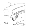
- Fig. 2 is a perspective view in partial cutaway illustrating mating of the exciter ring to the disc brake rotor in accordance with a first of two preferred embodiments of the invention.
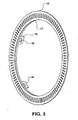
- Fig. 3 is a perspective view of an exciter ring in accordance with the first embodiment of the invention.
- Fig. 4 is a side elevation of the exciter ring of Fig. 3 .
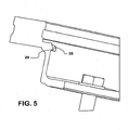
- Fig. 5 is a section view of a rotor constructed in accordance with the first embodiment.
- Fig. 6 is a cutaway view of rotor/exciter ring assembly in accordance with a second embodiment of the invention.
- Fig. 7 is a cutaway view of the rotor of Fig. 6 .
- Fig. 8 is a perspective view of the exciter ring for the second embodiment.
- Fig. 9 is a side elevation of the exciter ring of Fig. 8 .
- Fig. 1 an assembly 10 of a rotor 12 and an exciter ring 14 for a disc brake is shown.
- Exciter ring 14 is situated in a recess 16 in rotor 12, flat along one side of the ring against a shelf 24 (see Fig. 2 ). Shelf 24 is formed in rotor 12 during casting.
- Five tangs 18 are shown extending from an inner circumference 17 (see Fig. 3 ) of exciter ring 14. The number of tangs may be varied.
- the rings are preferably set at an oblique angle of 90 to 110 degrees with respect to the plane of the ring, and engage with rotor 12.
- Rotor 12 is a gray iron casting. Rotor 12 provides a wearable surface 22 which pads of the disc brake close on and wear against.
- Exciter ring 14, in both embodiments, is a stamped piece of mild low carbon steel, snap fit by tangs 18 onto the rotor and retained in position by the tangs.
- Exciter ring 14 is set as a recess 20 in rotor 12 centered within wearable surface 22.
- FIG. 2 details of exciter ring 14 and rotor 12 relating to capture between the elements are illustrated.
- exciter ring 14 is held along one major side to a shelf 24.
- One of tangs 18 is seen extending from the inner circumference 17 of exciter ring 14 into a deeper recess 20 in rotor 12. Tang 18 abuts along one side the inner cylindrical surface 21 of the deeper recess 20. Extending radially inwardly from the cylindrical surface 21 into recess 20 is a bead 26. Tang 18 operates as a catch, its sides defining an aperture 30 parallel to the interior surface forming recess 21.
- Tang 18 is captured on a bead 26 upon aligning the aperture 30 with the bead 26, holding the exciter ring 14 in place on rotor 12. Capture is assisted by the profile of bead 26, which has a bevel 28 facing the direction from which tang 18 is fitted into the recess 20. Beveled faces 57 are also applied to leading edges of the tangs 18. Upon introduction of the ring 14 into recess 16 each tang 18 is rotated into alignment with a bead 26 in the deeper recess 21. As ring 14 is moved axially into rotor 12 tangs 18 encounter the beveled surfaces 28 of the trapezoidally shaped beads 26 and ride up and over the beads before snapping down the far edge of the bead. A trapezoidal shape is not required. Only some sort of allowance between the ring and rotor is required. Beads 26 may be seen to not be a continuous ring, but as isolated raised points. This configuration serves to keep ring 14 from clocking.
- This first embodiment of the invention produces highly secure attachment between tang and rotor, but requires modification of molds in which rotors are cast to produce the beads 26.
- indentations 34 may be machined into the cylindrical interior surface 21 of rotors 12.
- Exciter rings 14 are then modified to attach to the indentations 34, as best seen in Fig. 7 .
- Indentations 34 are circumferentially distributed around the cylindrical surface 21.
- tangs 18 are modified to incorporate radially outwardly oriented projections 19 which are sized to fit into indentations 34. Projections 19 have a base inside tang 18 and extend outwardly toward the main body of exciter ring 18.
- Projections 19 can be seen to be partially punched out of the tangs, leaving an opening into which the projections can be pushed. Since the tangs 18 lead introduction of an exciter ring 14 to a rotor 12, the projections flatten into the openings in the tangs 18 as the ring is pushed into position on rotor 12.
- the projections 19 are, in effect, torsion springs which snap out along the trailing edge into indentations 34.
- the first embodiment of the invention emphasizes a secure attachment of the exciter ring 14 to a rotor 12 to minimize any prospect of clocking of the ring.
- the second embodiment of the invention costs less to produce than the first.
Landscapes
- Engineering & Computer Science (AREA)
- General Engineering & Computer Science (AREA)
- Mechanical Engineering (AREA)
- Transportation (AREA)
- Physics & Mathematics (AREA)
- General Physics & Mathematics (AREA)
- Braking Arrangements (AREA)
- Pharmaceuticals Containing Other Organic And Inorganic Compounds (AREA)
- Standing Axle, Rod, Or Tube Structures Coupled By Welding, Adhesion, Or Deposition (AREA)
- Pens And Brushes (AREA)
Claims (7)
- Ensemble d'un rotor de frein à disque comprenant :un rotor (12) en fonte destiné à tourner autour d'un axe, le rotor en fonte ayant une surface intérieure de forme cylindrique ; etun anneau (14) d'excitation en un matériau résistant à la corrosion et aplati pour définir des surfaces principales opposées et ayant des queues (18) disposées circonférenciellement les unes par rapport aux autres et. s'étendant d'une surface principale en coopération avec la surface intérieure de forme cylindrique du rotor (12) en fontecaractérisé en ce que
la surface intérieure de forme cylindrique est continue et dans lequel il comprend une pluralité d'indentations (34), et la pluralité d'indentations (34) est coplanaire et répartie circonférentiellement autour de la surface intérieure de forme cylindrique ;
et l'anneau d'excitation est inséré suivant une orientation qui met chacune de la pluralité de queues (18) en alignement avec l'une correspondante de la pluralité d'indentations (34) ;
et un élément (19) de retenu fait saillie vers l'extérieur de chaque queue (18) en coopération avec l'indentation voisine et maintient l'anneau (14) d'excitation en place sur le rotor (12) et empêche l'anneau (14) d'excitation de battre. - Ensemble d'un rotor de frein à disque comprenant :un rotor (12) en fonte destiné à tourner autour d'un axe, le rotor en fonte ayant une surface intérieure de forme cylindrique ; etun anneau (14) d'excitation en un matériau résistant à la corrosion et aplati pour définir des surfaces principales opposées et ayant des queues (18) disposées circonférenciellement les unes par rapport aux autres et s'étendant d'une surface principale en coopération avec la surface intérieure de forme cylindrique du rotor (12) en fonte, etcaractérisé en ce que
une pluralité de bourrelets (26) s'écarte de la surface intérieure de forme cylindrique, la pluralité de bourrelets (26) étant coplanaire et répartie circonférentiellement sous forme de points isolés autour de la surface intérieure de forme cylindrique ;
et l'anneau (14) d'excitation est inséré suivant une orientation alignant chacune de la pluralité des queues (18) avec l'un correspondant de la pluralité de bourrelets (26) ;
caractérisé en ce que
une ouverture (30) dans chaque queue (18), dans laquelle un bourrelet (26) est adapté pour retenir l'anneau (14) d'excitation, est en place et maintient l'anneau (14) d'excitation en place sur le rotor (12) et empêche l'anneau (14) d'excitation de battre. - Ensemble d'un rotor de frein à disque suivant la revendication 2 comprenant en outré
le fait que les bourrelets (26) ont une surface (57) biseautée faisant face dans une direction à partir de laquelle les queues (18) sont introduites. - Procédé de fabrication d'un ensemble de rotor de frein à disque, le procédé comprenant les stades dans lesquels :on se procure un rotor (12) ayant une surface intérieure de forme cylindrique ;on estampe un noyau (14) d'excitation en un matériau résistant à la corrosion par rapport au rotor (12) et aplati pour définir des surfaces principales opposées et munies de queues (18) disposées circonférentiellement et partant de l'un des côtés principaux de l'anneau d'excitation ; eton adapte l'anneau (14) d'excitation sur le rotor (12) alors que les queues (18) s'étendent à l'intérieur du rotor (12) défini par la surface intérieure de forme cylindrique et en contact avec la surface intérieure de forme cylindrique pour retenir l'anneau d'excitation sur le rotor (12) ; caractérisé en ce queon inclut une pluralité d'indentations (34) dans la surface intérieure de forme cylindrique qui est continue, la pluralité d'indentations (34) étant coplanaire et répartie circonférentiellement autour de la surface intérieure de forme cylindrique ;on met l'anneau (14) d'excitation en position pour mettre en position les queues (18) en contact avec la surface intérieure de forme cylindrique, chacune de la pluralité de queues (18) étant alignée sur l'une correspondante de la pluralité d'indentations (34) ; eton prévoit un élément (19) de retenu conjugué faisant saillie vers l'extérieur de chaque queue (18) pour coopérer avec son indentation voisine et pour maintenir l'anneau (14) d'excitation en place sur le rotor (12) et pour empêcher l'anneau (14) d'excitation de battre.
- Procédé d'un ensemble de rotor de frein à disque, le procédé comprenant les stades dans lesquels :on se procure un rotor (12) ayant une surface intérieure de forme cylindrique ;on estampe un noyau (14) d'excitation en un matériau résistant à la corrosion par rapport au rotor (12) et aplati pour définir des surfaces principales opposées et munies de queues (18) disposées circonférentiellement et partant de l'un des côtés principaux de l'anneau d'excitation ; eton adapte l'anneau (14) d'excitation sur le rotor (12) alors que les queues (18) s'étendent à l'intérieur du rotor (12) défini par la surface intérieure de forme cylindrique et en contact avec la surface intérieure de forme cylindrique pour retenir l'anneau d'excitation sur le rotor (12)on coule le rotor (12) dans un moule définissant une pluralité de bourrelets (26) sur la surface intérieure de forme cylindrique, la pluralité de bourrelets (26) étant coplanaire et répartie circonférentiellement sous forme de points isolés autour de la surface intérieure de forme cylindrique ;on insère l'anneau (14) d'excitation en le faisant tourner pour mettre chacune de la pluralité de queues (18) en alignement avec l'un différent de la pluralité de bourrelets (26) ;caractérisé en ce que
l'on ménage une ouverture (30) dans chaque queue (18) ; et
on adapte chaque ouverture (30) sur l'un correspondant de la pluralité de bourrelets (26) pour retenir l'anneau (14) d'excitation en place sur le rotor (12) et empêcher l'anneau (14) d'excitation de battre. - Procédé d'un ensemble de rotor de frein à disque suivant la revendication 5, comprenant donc les stades dans lesquels :on conforme le bourrelet (26) pour qu'il ait un biseau (57) disposé de manière à déplacer les queues (18) vers le haut, alors que la queue (18) est déplacée initialement sur le bourrelet (26).
- Procédé de fabrication d'un ensemble de rotor de frein à disque suivant la revendication 4, le procédé comprenant les stades supplémentaires de prévoir des faces (57) biseautées au bord menant des queues (18).
Applications Claiming Priority (1)
| Application Number | Priority Date | Filing Date | Title |
|---|---|---|---|
| US11/220,435 US7487862B2 (en) | 2005-09-07 | 2005-09-07 | Snap in ABS exciter ring |
Publications (3)
| Publication Number | Publication Date |
|---|---|
| EP1762743A2 EP1762743A2 (fr) | 2007-03-14 |
| EP1762743A3 EP1762743A3 (fr) | 2008-02-13 |
| EP1762743B1 true EP1762743B1 (fr) | 2010-04-14 |
Family
ID=37440686
Family Applications (1)
| Application Number | Title | Priority Date | Filing Date |
|---|---|---|---|
| EP06017574A Not-in-force EP1762743B1 (fr) | 2005-09-07 | 2006-08-23 | Roue polaire ABS avec connecteur encliquetable |
Country Status (6)
| Country | Link |
|---|---|
| US (1) | US7487862B2 (fr) |
| EP (1) | EP1762743B1 (fr) |
| AT (1) | ATE464489T1 (fr) |
| CA (1) | CA2557114A1 (fr) |
| DE (1) | DE602006013557D1 (fr) |
| MX (1) | MXPA06009568A (fr) |
Cited By (2)
| Publication number | Priority date | Publication date | Assignee | Title |
|---|---|---|---|---|
| WO2014132202A1 (fr) | 2013-02-26 | 2014-09-04 | Piaggio & C. S.P.A. | Disque de frein à disque et roue phonique |
| EP4129784A1 (fr) | 2021-08-03 | 2023-02-08 | Brembo North America, Inc. | Anneau de capteur antiblocage, bande de frein à disque et ensemble |
Families Citing this family (17)
| Publication number | Priority date | Publication date | Assignee | Title |
|---|---|---|---|---|
| USD605099S1 (en) | 2007-10-04 | 2009-12-01 | Schwabische Huttenwerke Automotive Gmbh & Co. Kg | Outer side portion of a brake rotor |
| US7980367B2 (en) * | 2008-01-30 | 2011-07-19 | Walther Engineering And Manufacturing Company, Inc. | Disc brake assembly with tone ring |
| DE102008017360B3 (de) * | 2008-04-04 | 2009-07-30 | Knorr-Bremse Systeme für Nutzfahrzeuge GmbH | Anordnung einer Bremsscheibe an einer Radnabe |
| US8020676B2 (en) * | 2008-08-08 | 2011-09-20 | International Truck Intellectual Property Company, Llc | Tone ring for an anti-lock brake system |
| EP3022457A4 (fr) | 2013-07-19 | 2017-04-26 | Hendrickson USA, L.L.C. | Rotor de frein à disque perfectionné pour véhicules utilitaires lourds |
| WO2015189785A1 (fr) | 2014-06-11 | 2015-12-17 | Freni Brembo S.P.A. | Frein à disque à bague d'excitation |
| US9594090B2 (en) * | 2015-04-10 | 2017-03-14 | Ford Global Technologies, Llc | Press-fit tone wheel for a speed-sensing apparatus |
| US9759281B1 (en) | 2016-03-09 | 2017-09-12 | Consolidated Metco, Inc. | Tone ring attachment method |
| US9964164B1 (en) * | 2017-02-01 | 2018-05-08 | Consolidated Metco, Inc. | Disc brake tone ring |
| US10495163B2 (en) | 2017-04-26 | 2019-12-03 | Hendrickson Usa, L.L.C. | Tone ring and attachment structure |
| DE102017112075A1 (de) * | 2017-06-01 | 2018-12-06 | Knorr-Bremse Systeme für Nutzfahrzeuge GmbH | An einem drehbaren Bauteil eines Kraftfahrzeuges verdrehsicher gehaltenes Polrad |
| DE102017112077A1 (de) * | 2017-06-01 | 2018-12-06 | Knorr-Bremse Systeme für Nutzfahrzeuge GmbH | Polrad eines Antiblockiersystems |
| US11131355B2 (en) | 2017-10-24 | 2021-09-28 | Hendrickson Usa, L.L.C. | ABS tone ring mounting structure |
| TWI656286B (zh) * | 2017-12-19 | 2019-04-11 | 至興精機股份有限公司 | Floating disc containing forged workpieces |
| US10704602B2 (en) * | 2018-05-21 | 2020-07-07 | Arvinmeritor Technology, Llc | Brake rotor and tone ring assembly |
| US12571441B2 (en) | 2020-05-05 | 2026-03-10 | Consolidated Metco, Inc. | Commercial vehicle brake rotor |
| US20240182010A1 (en) * | 2022-12-01 | 2024-06-06 | Donald Pieronek | Retrofit Anti-lock Braking Tone Ring and Sensing System |
Family Cites Families (14)
| Publication number | Priority date | Publication date | Assignee | Title |
|---|---|---|---|---|
| US4534088A (en) * | 1983-08-29 | 1985-08-13 | James Ricke | Hole plug |
| US4840291A (en) * | 1986-08-18 | 1989-06-20 | Hillwell Manufacturing Inc. | Container dispensing system |
| US4898493A (en) * | 1989-03-16 | 1990-02-06 | Karl Blankenburg | Method and apparatus for assembling parts |
| US5067597A (en) * | 1989-08-25 | 1991-11-26 | Young Warren J | Hub and exciter ring assembly |
| DE4230012C2 (de) | 1992-09-08 | 1999-08-26 | Knorr Bremse Systeme | ABS-überwachtes Fahrzeugrad |
| US5263900A (en) * | 1992-11-12 | 1993-11-23 | The Budd Company | ABS wheel hub assembly and method of making the same |
| DE4402959C2 (de) | 1994-02-01 | 1997-02-20 | Bpw Bergische Achsen Kg | Vorrichtung zur Impulserzeugung an Fahrzeugrädern |
| JPH08146021A (ja) | 1994-11-16 | 1996-06-07 | Nissan Motor Co Ltd | Abs車輪回転センサ用ロータの取付構造およびそのロータの製造方法 |
| WO2003017896A1 (fr) * | 2001-08-08 | 2003-03-06 | Biotap A/S | Raccord permettant d'assembler deux dispositifs et procede d'utilisation associe |
| DE10145947C1 (de) | 2001-09-18 | 2002-11-21 | Wabco Perrot Bremsen Gmbh | Bremse |
| US6568512B1 (en) * | 2002-05-16 | 2003-05-27 | International Truck Intellectual Property Company, Llc | Corrosion resistant cast-in insert exciter ring |
| DE10237504B4 (de) | 2002-08-16 | 2006-11-09 | Knorr-Bremse Systeme für Nutzfahrzeuge GmbH | Vorrichtung zur Impulserzeugung an einem Fahrzeugrad und Verfahren zur Montage der Vorrichtung |
| US6945367B1 (en) * | 2004-05-24 | 2005-09-20 | Robert Bosch Gmbh | Rotor and exciter ring |
| US7219778B2 (en) * | 2004-10-29 | 2007-05-22 | Gunite Corporation | Exciter ring for a brake rotor |
-
2005
- 2005-09-07 US US11/220,435 patent/US7487862B2/en not_active Expired - Fee Related
-
2006
- 2006-08-23 MX MXPA06009568A patent/MXPA06009568A/es active IP Right Grant
- 2006-08-23 DE DE602006013557T patent/DE602006013557D1/de active Active
- 2006-08-23 AT AT06017574T patent/ATE464489T1/de not_active IP Right Cessation
- 2006-08-23 EP EP06017574A patent/EP1762743B1/fr not_active Not-in-force
- 2006-08-24 CA CA002557114A patent/CA2557114A1/fr not_active Abandoned
Cited By (2)
| Publication number | Priority date | Publication date | Assignee | Title |
|---|---|---|---|---|
| WO2014132202A1 (fr) | 2013-02-26 | 2014-09-04 | Piaggio & C. S.P.A. | Disque de frein à disque et roue phonique |
| EP4129784A1 (fr) | 2021-08-03 | 2023-02-08 | Brembo North America, Inc. | Anneau de capteur antiblocage, bande de frein à disque et ensemble |
Also Published As
| Publication number | Publication date |
|---|---|
| DE602006013557D1 (de) | 2010-05-27 |
| EP1762743A3 (fr) | 2008-02-13 |
| CA2557114A1 (fr) | 2007-03-07 |
| US20070051571A1 (en) | 2007-03-08 |
| ATE464489T1 (de) | 2010-04-15 |
| MXPA06009568A (es) | 2007-03-28 |
| EP1762743A2 (fr) | 2007-03-14 |
| US7487862B2 (en) | 2009-02-10 |
Similar Documents
| Publication | Publication Date | Title |
|---|---|---|
| EP1762743B1 (fr) | Roue polaire ABS avec connecteur encliquetable | |
| US11773937B2 (en) | Anti-lock sensor ring, disk brake band and assembly | |
| JP4726375B2 (ja) | ブラシシール | |
| US8020676B2 (en) | Tone ring for an anti-lock brake system | |
| RU2438019C2 (ru) | Узел лопатки турбины | |
| JP6158890B2 (ja) | ブレーキアセンブリ | |
| US5166611A (en) | Tone wheel with coined serrations for engaging an annular support surface and method of assembling same on a wheel bearing seal | |
| JP3511294B2 (ja) | 特に自動車の駆動系統のためのフレキシブルディスク | |
| US8584815B2 (en) | Disc brake assembly | |
| CN102066800B (zh) | 包括轮毂装置和制动盘的系统 | |
| EP3184845B1 (fr) | Rotor de frein à disque ventilé de surface | |
| JP6567708B2 (ja) | ディスクブレーキトーンリング | |
| JP4777457B2 (ja) | 特にホイールハブのための環状シール組立体 | |
| JP2000512749A (ja) | 磁性リング | |
| JPH01126419A (ja) | 軸受組立体 | |
| WO2024141659A1 (fr) | Élément de retenue pour fixer des éléments ou des installations sur un arbre | |
| JPS6157501B2 (fr) | ||
| CN118167747A (zh) | 包括可膨胀转子的制动组件 | |
| JPS6132175Y2 (fr) | ||
| JPH0655808U (ja) | 自動車の車軸用オイルシール |
Legal Events
| Date | Code | Title | Description |
|---|---|---|---|
| PUAI | Public reference made under article 153(3) epc to a published international application that has entered the european phase |
Free format text: ORIGINAL CODE: 0009012 |
|
| AK | Designated contracting states |
Kind code of ref document: A2 Designated state(s): AT BE BG CH CY CZ DE DK EE ES FI FR GB GR HU IE IS IT LI LT LU LV MC NL PL PT RO SE SI SK TR |
|
| AX | Request for extension of the european patent |
Extension state: AL BA HR MK YU |
|
| PUAL | Search report despatched |
Free format text: ORIGINAL CODE: 0009013 |
|
| AK | Designated contracting states |
Kind code of ref document: A3 Designated state(s): AT BE BG CH CY CZ DE DK EE ES FI FR GB GR HU IE IS IT LI LT LU LV MC NL PL PT RO SE SI SK TR |
|
| AX | Request for extension of the european patent |
Extension state: AL BA HR MK YU |
|
| 17P | Request for examination filed |
Effective date: 20080613 |
|
| 17Q | First examination report despatched |
Effective date: 20080714 |
|
| AKX | Designation fees paid |
Designated state(s): AT DE FR GB IT SE |
|
| GRAP | Despatch of communication of intention to grant a patent |
Free format text: ORIGINAL CODE: EPIDOSNIGR1 |
|
| GRAS | Grant fee paid |
Free format text: ORIGINAL CODE: EPIDOSNIGR3 |
|
| GRAA | (expected) grant |
Free format text: ORIGINAL CODE: 0009210 |
|
| AK | Designated contracting states |
Kind code of ref document: B1 Designated state(s): AT DE FR GB IT SE |
|
| REG | Reference to a national code |
Ref country code: GB Ref legal event code: FG4D |
|
| REF | Corresponds to: |
Ref document number: 602006013557 Country of ref document: DE Date of ref document: 20100527 Kind code of ref document: P |
|
| PG25 | Lapsed in a contracting state [announced via postgrant information from national office to epo] |
Ref country code: SE Free format text: LAPSE BECAUSE OF FAILURE TO SUBMIT A TRANSLATION OF THE DESCRIPTION OR TO PAY THE FEE WITHIN THE PRESCRIBED TIME-LIMIT Effective date: 20100414 |
|
| PG25 | Lapsed in a contracting state [announced via postgrant information from national office to epo] |
Ref country code: AT Free format text: LAPSE BECAUSE OF FAILURE TO SUBMIT A TRANSLATION OF THE DESCRIPTION OR TO PAY THE FEE WITHIN THE PRESCRIBED TIME-LIMIT Effective date: 20100414 |
|
| PGFP | Annual fee paid to national office [announced via postgrant information from national office to epo] |
Ref country code: DE Payment date: 20100831 Year of fee payment: 5 |
|
| PLBE | No opposition filed within time limit |
Free format text: ORIGINAL CODE: 0009261 |
|
| STAA | Information on the status of an ep patent application or granted ep patent |
Free format text: STATUS: NO OPPOSITION FILED WITHIN TIME LIMIT |
|
| 26N | No opposition filed |
Effective date: 20110117 |
|
| PG25 | Lapsed in a contracting state [announced via postgrant information from national office to epo] |
Ref country code: IT Free format text: LAPSE BECAUSE OF FAILURE TO SUBMIT A TRANSLATION OF THE DESCRIPTION OR TO PAY THE FEE WITHIN THE PRESCRIBED TIME-LIMIT Effective date: 20100414 |
|
| GBPC | Gb: european patent ceased through non-payment of renewal fee |
Effective date: 20100823 |
|
| REG | Reference to a national code |
Ref country code: FR Ref legal event code: ST Effective date: 20110502 |
|
| PG25 | Lapsed in a contracting state [announced via postgrant information from national office to epo] |
Ref country code: FR Free format text: LAPSE BECAUSE OF NON-PAYMENT OF DUE FEES Effective date: 20100831 |
|
| PG25 | Lapsed in a contracting state [announced via postgrant information from national office to epo] |
Ref country code: GB Free format text: LAPSE BECAUSE OF NON-PAYMENT OF DUE FEES Effective date: 20100823 |
|
| REG | Reference to a national code |
Ref country code: DE Ref legal event code: R119 Ref document number: 602006013557 Country of ref document: DE Effective date: 20120301 |
|
| PG25 | Lapsed in a contracting state [announced via postgrant information from national office to epo] |
Ref country code: DE Free format text: LAPSE BECAUSE OF NON-PAYMENT OF DUE FEES Effective date: 20120301 |