EP1764436A1 - Waschmaschine mit Auswuchtvorrichtung - Google Patents
Waschmaschine mit Auswuchtvorrichtung Download PDFInfo
- Publication number
- EP1764436A1 EP1764436A1 EP06026323A EP06026323A EP1764436A1 EP 1764436 A1 EP1764436 A1 EP 1764436A1 EP 06026323 A EP06026323 A EP 06026323A EP 06026323 A EP06026323 A EP 06026323A EP 1764436 A1 EP1764436 A1 EP 1764436A1
- Authority
- EP
- European Patent Office
- Prior art keywords
- drum
- imbalance
- load
- masses
- processor
- Prior art date
- Legal status (The legal status is an assumption and is not a legal conclusion. Google has not performed a legal analysis and makes no representation as to the accuracy of the status listed.)
- Withdrawn
Links
- 238000012937 correction Methods 0.000 claims abstract description 88
- 238000007792 addition Methods 0.000 claims abstract description 24
- 230000018044 dehydration Effects 0.000 claims abstract description 21
- 238000006297 dehydration reaction Methods 0.000 claims abstract description 21
- 230000004913 activation Effects 0.000 claims abstract description 7
- 238000012544 monitoring process Methods 0.000 claims abstract description 7
- XLYOFNOQVPJJNP-UHFFFAOYSA-N water Substances O XLYOFNOQVPJJNP-UHFFFAOYSA-N 0.000 claims description 36
- 230000001133 acceleration Effects 0.000 claims description 19
- 238000001914 filtration Methods 0.000 claims description 9
- 238000003860 storage Methods 0.000 claims description 8
- 230000003750 conditioning effect Effects 0.000 claims description 2
- 239000013598 vector Substances 0.000 description 53
- 238000000034 method Methods 0.000 description 31
- 230000004044 response Effects 0.000 description 28
- 239000011159 matrix material Substances 0.000 description 22
- 238000005406 washing Methods 0.000 description 22
- 230000003068 static effect Effects 0.000 description 15
- 230000000694 effects Effects 0.000 description 11
- 238000005259 measurement Methods 0.000 description 11
- 238000009987 spinning Methods 0.000 description 11
- 239000000725 suspension Substances 0.000 description 9
- 230000008859 change Effects 0.000 description 8
- 238000005070 sampling Methods 0.000 description 8
- 230000009471 action Effects 0.000 description 7
- 230000008901 benefit Effects 0.000 description 6
- 230000036962 time dependent Effects 0.000 description 6
- 238000013459 approach Methods 0.000 description 5
- 238000000429 assembly Methods 0.000 description 5
- 230000000712 assembly Effects 0.000 description 5
- 238000010586 diagram Methods 0.000 description 5
- 238000012935 Averaging Methods 0.000 description 4
- 230000008878 coupling Effects 0.000 description 4
- 238000010168 coupling process Methods 0.000 description 4
- 238000005859 coupling reaction Methods 0.000 description 4
- 238000001514 detection method Methods 0.000 description 4
- 230000006870 function Effects 0.000 description 4
- 238000011068 loading method Methods 0.000 description 4
- 230000008569 process Effects 0.000 description 4
- 238000010276 construction Methods 0.000 description 3
- 238000006073 displacement reaction Methods 0.000 description 3
- 238000001035 drying Methods 0.000 description 3
- 230000005484 gravity Effects 0.000 description 3
- 239000007788 liquid Substances 0.000 description 3
- 238000004458 analytical method Methods 0.000 description 2
- 238000005452 bending Methods 0.000 description 2
- 238000006243 chemical reaction Methods 0.000 description 2
- 230000006872 improvement Effects 0.000 description 2
- 230000007246 mechanism Effects 0.000 description 2
- 238000003856 thermoforming Methods 0.000 description 2
- 230000001052 transient effect Effects 0.000 description 2
- 238000003809 water extraction Methods 0.000 description 2
- 238000000071 blow moulding Methods 0.000 description 1
- 238000004364 calculation method Methods 0.000 description 1
- 230000000295 complement effect Effects 0.000 description 1
- 238000011217 control strategy Methods 0.000 description 1
- 238000013016 damping Methods 0.000 description 1
- 230000001419 dependent effect Effects 0.000 description 1
- 238000013461 design Methods 0.000 description 1
- 238000009826 distribution Methods 0.000 description 1
- 238000002474 experimental method Methods 0.000 description 1
- 238000001125 extrusion Methods 0.000 description 1
- 239000004744 fabric Substances 0.000 description 1
- 238000011049 filling Methods 0.000 description 1
- 238000005304 joining Methods 0.000 description 1
- 238000010412 laundry washing Methods 0.000 description 1
- 238000004519 manufacturing process Methods 0.000 description 1
- 238000013507 mapping Methods 0.000 description 1
- 239000000463 material Substances 0.000 description 1
- 239000002184 metal Substances 0.000 description 1
- 238000012545 processing Methods 0.000 description 1
- 230000008707 rearrangement Effects 0.000 description 1
- 230000003014 reinforcing effect Effects 0.000 description 1
- 230000003252 repetitive effect Effects 0.000 description 1
- 238000005728 strengthening Methods 0.000 description 1
- 238000012360 testing method Methods 0.000 description 1
- 238000004804 winding Methods 0.000 description 1
Images


Classifications
-
- D—TEXTILES; PAPER
- D06—TREATMENT OF TEXTILES OR THE LIKE; LAUNDERING; FLEXIBLE MATERIALS NOT OTHERWISE PROVIDED FOR
- D06F—LAUNDERING, DRYING, IRONING, PRESSING OR FOLDING TEXTILE ARTICLES
- D06F33/00—Control of operations performed in washing machines or washer-dryers
- D06F33/30—Control of washing machines characterised by the purpose or target of the control
- D06F33/48—Preventing or reducing imbalance or noise
-
- D—TEXTILES; PAPER
- D06—TREATMENT OF TEXTILES OR THE LIKE; LAUNDERING; FLEXIBLE MATERIALS NOT OTHERWISE PROVIDED FOR
- D06F—LAUNDERING, DRYING, IRONING, PRESSING OR FOLDING TEXTILE ARTICLES
- D06F33/00—Control of operations performed in washing machines or washer-dryers
- D06F33/30—Control of washing machines characterised by the purpose or target of the control
- D06F33/32—Control of operational steps, e.g. optimisation or improvement of operational steps depending on the condition of the laundry
- D06F33/40—Control of operational steps, e.g. optimisation or improvement of operational steps depending on the condition of the laundry of centrifugal separation of water from the laundry
-
- D—TEXTILES; PAPER
- D06—TREATMENT OF TEXTILES OR THE LIKE; LAUNDERING; FLEXIBLE MATERIALS NOT OTHERWISE PROVIDED FOR
- D06F—LAUNDERING, DRYING, IRONING, PRESSING OR FOLDING TEXTILE ARTICLES
- D06F34/00—Details of control systems for washing machines, washer-dryers or laundry dryers
- D06F34/14—Arrangements for detecting or measuring specific parameters
- D06F34/16—Imbalance
-
- D—TEXTILES; PAPER
- D06—TREATMENT OF TEXTILES OR THE LIKE; LAUNDERING; FLEXIBLE MATERIALS NOT OTHERWISE PROVIDED FOR
- D06F—LAUNDERING, DRYING, IRONING, PRESSING OR FOLDING TEXTILE ARTICLES
- D06F37/00—Details specific to washing machines covered by groups D06F21/00 - D06F25/00
- D06F37/20—Mountings, e.g. resilient mountings, for the rotary receptacle, motor, tub or casing; Preventing or damping vibrations
- D06F37/22—Mountings, e.g. resilient mountings, for the rotary receptacle, motor, tub or casing; Preventing or damping vibrations in machines with a receptacle rotating or oscillating about a horizontal axis
- D06F37/225—Damping vibrations by displacing, supplying or ejecting a material, e.g. liquid, into or from counterbalancing pockets
-
- D—TEXTILES; PAPER
- D06—TREATMENT OF TEXTILES OR THE LIKE; LAUNDERING; FLEXIBLE MATERIALS NOT OTHERWISE PROVIDED FOR
- D06F—LAUNDERING, DRYING, IRONING, PRESSING OR FOLDING TEXTILE ARTICLES
- D06F37/00—Details specific to washing machines covered by groups D06F21/00 - D06F25/00
- D06F37/30—Driving arrangements
- D06F37/304—Arrangements or adaptations of electric motors
-
- D—TEXTILES; PAPER
- D06—TREATMENT OF TEXTILES OR THE LIKE; LAUNDERING; FLEXIBLE MATERIALS NOT OTHERWISE PROVIDED FOR
- D06F—LAUNDERING, DRYING, IRONING, PRESSING OR FOLDING TEXTILE ARTICLES
- D06F39/00—Details of washing machines not specific to a single type of machines covered by groups D06F9/00 - D06F27/00
- D06F39/12—Casings; Tubs
- D06F39/125—Supporting arrangements for the casing, e.g. rollers or legs
-
- D—TEXTILES; PAPER
- D06—TREATMENT OF TEXTILES OR THE LIKE; LAUNDERING; FLEXIBLE MATERIALS NOT OTHERWISE PROVIDED FOR
- D06F—LAUNDERING, DRYING, IRONING, PRESSING OR FOLDING TEXTILE ARTICLES
- D06F2103/00—Parameters monitored or detected for the control of domestic laundry washing machines, washer-dryers or laundry dryers
- D06F2103/26—Imbalance; Noise level
-
- D—TEXTILES; PAPER
- D06—TREATMENT OF TEXTILES OR THE LIKE; LAUNDERING; FLEXIBLE MATERIALS NOT OTHERWISE PROVIDED FOR
- D06F—LAUNDERING, DRYING, IRONING, PRESSING OR FOLDING TEXTILE ARTICLES
- D06F2105/00—Systems or parameters controlled or affected by the control systems of washing machines, washer-dryers or laundry dryers
- D06F2105/54—Changing between normal operation mode and special operation modes, e.g. service mode, component cleaning mode or stand-by mode
-
- D—TEXTILES; PAPER
- D06—TREATMENT OF TEXTILES OR THE LIKE; LAUNDERING; FLEXIBLE MATERIALS NOT OTHERWISE PROVIDED FOR
- D06F—LAUNDERING, DRYING, IRONING, PRESSING OR FOLDING TEXTILE ARTICLES
- D06F37/00—Details specific to washing machines covered by groups D06F21/00 - D06F25/00
- D06F37/20—Mountings, e.g. resilient mountings, for the rotary receptacle, motor, tub or casing; Preventing or damping vibrations
- D06F37/24—Mountings, e.g. resilient mountings, for the rotary receptacle, motor, tub or casing; Preventing or damping vibrations in machines with a receptacle rotating or oscillating about a vertical axis
- D06F37/245—Damping vibrations by displacing, supplying or ejecting a material, e.g. liquid, into or from counterbalancing pockets
-
- Y—GENERAL TAGGING OF NEW TECHNOLOGICAL DEVELOPMENTS; GENERAL TAGGING OF CROSS-SECTIONAL TECHNOLOGIES SPANNING OVER SEVERAL SECTIONS OF THE IPC; TECHNICAL SUBJECTS COVERED BY FORMER USPC CROSS-REFERENCE ART COLLECTIONS [XRACs] AND DIGESTS
- Y02—TECHNOLOGIES OR APPLICATIONS FOR MITIGATION OR ADAPTATION AGAINST CLIMATE CHANGE
- Y02B—CLIMATE CHANGE MITIGATION TECHNOLOGIES RELATED TO BUILDINGS, e.g. HOUSING, HOUSE APPLIANCES OR RELATED END-USER APPLICATIONS
- Y02B40/00—Technologies aiming at improving the efficiency of home appliances, e.g. induction cooking or efficient technologies for refrigerators, freezers or dish washers
Definitions
- This invention relates to a system for balancing the load in a laundry appliance, particularly but not solely, a system for balancing the load in a horizontal axis washing machine.
- the ideal approach is to eliminate the problem at its source, for which there are various solutions.
- the first possibility is to ensure that the wash load is evenly distributed prior to spinning. This is an effective solution but it is extremely difficult to achieve in practice. Therefore while steps can be taken to reduce the degree of imbalance that must be catered for, it is not possible to eliminate it sufficiently to ignore it there after.
- Another approach is to determine the size and nature of the imbalance, and add an imbalance that exactly counteracts the first.
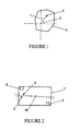
- Static imbalance is where axis of rotation does not pass through the Centre of Gravity (CoG) of the object. This means that a force, F, must be applied to the object (acting through the CoG) to keep accelerating the object towards the axis of rotation. This force must come from the surrounding structure and of course its direction rotates with the object, as illustrated in Figure 1.
- F Force
- the present invention consists in a laundry appliance comprising:
- the present invention consists in a laundry appliance having a perforated drum for dehydrating a clothes load, driving means adapted to rotate said drum at speed thereby dehydrating the load and a system for compensating for imbalances of said drum and any load carried therein during dehydration of the load, said system comprising:
- the present invention consists in a laundry appliance having a perforated drum for dehydrating a clothes load, driving means adapted to rotate said drum at speed thereby dehydrating the load and a system for compensating for imbalances of said drum and any load carried therein during dehydration of the load, said system comprising:
- the present invention consists in a laundry appliance having a perforated drum for dehydrating a clothes load, driving means adapted to rotate said drum at speed thereby dehydrating the load and a system for compensating for imbalances of said drum and any load carried therein during dehydration of the load, said system comprising:
- the present invention provides a novel method of balancing the load in a laundry appliance, particularly suited to washing machines. Such a system dispenses with the need for suspension, and this significantly simplifies the machine design.
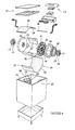
- FIGS 3 and 4 show a washing machine of the horizontal axis type, having a perforated drum 11 supported with its axis substantially horizontal in side-to-side orientation within a cabinet 12.
- the cabinet 12 includes surfaces which confine wash or rinse liquid leaving the drum within a water tight enclosure. Some parts of the cabinet structure 12 may be formed together with the liquid confining surfaces by for example twin-sheet thermoforming. In particular the back and side walls ofthe machine may be formed in this way.
- the laundry handling system including the drum and many other components is preferably contained in a top loading configuration.
- the horizontal axis spin drum 11 is contained within a substantially rectangular cabinet 12 with access being provided via a hinged lid 14 on the top of the machine.
- Other horizontal axis configurations may be adopted.
- the drum 11 is rotatably supported by bearings 15 at either end which in turn are each supported by a drum support 16.
- the bearings are axially located, externally, on a shaft means 19 protruding from the hub area 20 of the drum ends 21,22.
- Other axial configurations are equally possible, for example internally located in a well in the outer face of the hub area of the drum to be located on a shaft protruding from the drum support.
- the drum supports 16 are shown each as a base supported unit and have integrated form, which again is ideally suited to manufacture by twin sheet thermoforming, blow moulding or the like.
- Each drum support preferably includes a strengthening rib area 23 and a drum accommodating well area 25 as depicted to accommodate the respective drum end 21, 22 of the drum 1.
- the drum supports 16 engage with sub-structure by interlocking within complementary surfaces provided in side walls 27,28. Other less preferable constructions are possible, such as frameworks formed from individual members or mechanical suspension systems.
- the drum supports 16 each include a bearing support well at the centre of said well area 25.
- a bearing mount 29 is located within the bearing support well, and in turn the bearing 15 fits within a boss in the bearing mount 29.
- the drum 11 comprises a perforated metal hoop 30, a pair of ends 21, 22 enclosing the ends of the hoop 30 to form a substantially cylindrical chamber and a pair of vanes 31 extending between the drum ends 21, 22.
- the drum is driven only from one end 21 and consequently one purpose of the vanes 31 is to transmit rotational torque to the nondriven drum end 22.
- the vanes also provide longitudinal rigidity to the drum assembly 11.
- the vanes 30 are wide and shallow, although they have sufficient depth and internal reinforcing to achieve any required resistance to buckling due to unbalanced dynamic loads.
- the vanes 30 have a distinct form, including a leading and trailing edge to assist in tumbling the washing load.
- the vanes 30 are oriented oppositely in a rotational direction, so that under rotation in either direction one vane is going forwards and the other backwards. This vane configuration provides further benefits in providing a user friendly opening into the washing chamber as is described below.
- the drum 11 is supported between a pair of drum supports 16 one at either end thereof.
- Access to the interior of the drum 11 is provided through a slide away hatch section 33 in the cylindrical wall 30 of the drum.
- the hatch section is connected through a latching mechanism 34, 35, 36, 37, 38 such that it is connected in a continuous loop during operation.
- the cabinet 12 of the washing machine is formed to provide access to the drum 11 in a substantially top loading fashion, rather than the traditional front loading fashion more common to horizontal axis machines.
- the washing machine includes an electric motor (rotor 39 and stator 40 visible in Figure 4) to effect rotation of the drum during all phases of operation (wash, rinse and spin dry).
- the motor is a direct drive inside-out electronically commutated brushless dc motor having a permanent magnet rotor 39 coupled to one end 21 of the drum 11 and stator 40 coupled to the drum support 16.
- a suitable form of motor is described in EP0361775 .
- a user interface 24 is provided, allowing user control over the functions and operation of the machine.
- the control electronics are integrally contained within the interface module, and provide electronic control over the operation of the machine.
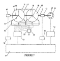
- a dynamically controlled balancing system uses electrical signals generated by the deformation of load cells in the bearing mounts 29 at each end of the shaft 19 to assess the required weight distribution correction that is required to dynamically rebalance the drum 11.
- Each bearing mount 29 is formed with a pair of bending bridges 40,41 and mounted on each bending bridge is a load cell 42 as shown in Figure 5.
- the outputs of the load cells 42 are fed to the control processor of the laundry machine to effect the balancing task, which is achieved by the addition of water to one or more of the six balancing chambers 43,46,47,80,81,82 located in the drum, as shown in Figure 6. There are three such chambers at each end spaced 120° apart and positioned on the extremity of the drum end 21,22.
- the output from the load cells 42 is first passed through filtering 50 before connection to the inputs of a microprocessor 51, which may be task specific or the main control processor for the laundry machine.
- the various algorithms (detailed later) programmed into the microprocessor 51 will dictate spin commands (eg: speed up/slow down) to the motor controller 52 and balancing corrections (eg: open/close valve 54) to the valve driver 53.
- the motor controller 52 in turn, will vary its energisation of the motor windings to achieve the spin command.
- the valve driver 53 will open or close the appropriate balancing valve 54, which allows water to flow through the injector 44 into the relevant slot 45 whereupon it is channelled to the appropriate chamber.
- the valve driver 53 also allows switching between coarse and fine control modes by switching the water flow through the high 55 and low 56 flow rate valves respectively.
- Pieces of information are typically obtained by measuring either acceleration, velocity, force, or displacement at two independent locations on the vibrating system.
- the reason that only two sensor locations are required and not four is that because the relevant signals are sinusoidal in time and therefore contain two pieces of information.
- One is the magnitude of the signal, and the other is the "phase" angle with respect to some reference point on the spinning system.
- the technique for acquiring data on the imbalance is difficult to implement in practice. This is because some types of signal are more difficult to measure than others, and even if good signals are obtained, the response matrix can become a unpredictable and difficult thing to know (or learn) depending where the signals are measured.
- the imbalance is characterised using force or stress measurement. Of the available alternatives force is easy to measure and the signal level is quite adequate at low speeds.
- the desirable signals for the purpose of balancing are a radial component of force at each bearing assembly supporting the drum, and thus two load cells of some sort are required.
- a pair of sensors 42 are located at either end of the shaft 19 as shown in Figure 4.
- a strain sensor suited to this application is the piezo disc. This type of sensor produces a large signal output and so is not significantly affected by RFI. However a piezo strain sensor can only measure fluctuations in load due to charge leakage across the disc.
- the piezo disc will have a particular response in relation to applied force. Since force is proportional to frequency squared and the response magnitude is proportional to force frequency, the relationship between sensor output and rpm of the drum is cubic.
- the bearing mount looks like two concentric cylindrical rings 46, 47, as illustrated in Figure 5.
- the load bridges 40, 41 described previously are connected at the top and bottom of the inner ring 47, respectively, and to opposite parts of the upper periphery of the outer ring 46.
- a piezo disc 42 is adhered to the loading bridge onto the side facing the outer ring.
- the load from the drum is taken through a bearing 15 mounted in the internal ring 47, through the load bridges 48 and load cell 42 into the outer ring 46, and out into the external structure. It will be appreciated that in this fashion the load bridges will flex according to any vertical forces from the spinning of the drum, thus deforming the piezo disc and providing a signal representative of the imbalance force.
- a dynamic control method is used. This is not in any way to be confused with static and dynamic imbalance as explained earlier, it simply refers to the nature of the control methodology.
- the alternative control methodology is 'static'.
- a static control method does not make use of or retain data on the time dependent behaviour of its target system. As a result the method is executed as a 'single shot' attempt to restore equilibrium, and sufficient time must be allowed to lapse after each execution so that the system has returned to a steady state condition prior to the next execution.
- a dynamic control method can anticipate the time dependent behaviour of the system and by storing recent past actions it is able to continuously correct the system, even while the system is in transient response.
- the main advantage of the preferred dynamic control is that the control loop is able to adjust for discrepancies as and when they appear rather than having to wait for the next execution time to come round. For systems with slow time response this is a considerable advantage.
- the controller must be programmed with an estimate of the time dependent response of the target system. However, provided it has no significant quirks, this only needs to be roughly approximated and the approach will still work well. Also, because the dynamic controller runs on a fast decision loop, any noise on the input parameters will result in many small corrections being made that are completely unnecessary. For this reason a minimum threshold correction level must be established where there is any cost or difficulty associated with effecting a correction.
- the present controller must be programmed with an approximation ofthe time dependent behaviour of the machine. More precisely it must know how much to weight its past actions (as a function of how long ago they were made) when deciding on what corrections, if any, are to be implemented.
- the sum of the appropriately weighted past history of water addition can be considered to be 'Effect in Waiting'; i.e. the controller is still anticipating that the effect of a certain quantity is still to come through on the signals, and thus must subtract this 'Effect in Waiting' from the presently calculated water requirements when deciding which valves should be on and which should be off at present.
- the balance controller must not address two chambers at once at one end unless it is clear that neither of them could be due to noise, i.e. both of them require a similar amount of water.
- the ends of the machine are not truly independent systems but are weakly coupled ( as will be discussed later) then large out of balance forces at one end cause 'ghost images' at the other, thus the balance controller must not address two ends at the same time unless it is clear that neither of them could be ghost images, i.e. both ends require a similar amount of water.
- the easiest way to address both of these problems is identify the maximum water requirement out of the six chambers and to then set a dynamic 'noise' threshold equal to half of this value of water (as shown in Figure 10).
- a water valve (e.g. 5) is then only turned on if the result 72 of its present requirements 70, minus its present effect in waiting 71, minus the noise value, is greater than the increment value mentioned above. It is here that we perform our magnitude calibration by adjusting this increment value.
- a small amount of hysteresis is necessary to prevent repetitive short valve actuations. This is simply achieved by using the above criterion for deciding when to turn a valve on, but using a different criterion when deciding when to turn it off again.
- the off criterion is more simple: a water valve is only turned off once its present requirements is less than its present effect in waiting. In other words once the valve is on it is not turned off until its chamber requirements are addressed.
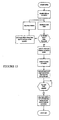
- the task of spinning while balancing actively can be subdivided into three sub-tasks or algorithms: Imbalance Detection Algorithm (IDA) Balance Correction Algorithm (BCA) Spin Algorithm (SA)
- IDA Imbalance Detection Algorithm
- BCA Balance Correction Algorithm
- SA Spin Algorithm
- the Imbalance Detection Algorithm (IDA) (shown in Figure 11) is concerned solely with the acquisition of imbalance related data, and is embedded in the motor control routine. It is active whenever the motor is turning, and makes its results available for the Balance Correction Algorithm (BCA) to see.
- IDA Imbalance Detection Algorithm
- the Spin Algorithm (shown in Figure 13) is concerned solely with executing the spin profile asked of it. It ramps the speed of the machine according to the profile requested and the vibration level determined by IDA.
- BCA (shown in Figure 12) is concerned solely with correcting whatever imbalance IDA has determined is there. It is an advanced control algorithm that takes into account the time dependent behaviour of both the machine and IDA. BCA is active whenever the rotation speed of the machine is greater than approximately 150 rpm.
- the discrete Fourier analysis may be made considerably more simple if the sampling is performed using a fixed number of samples per revolution rather than a fixed frequency.
- This requires a rotary encoder, which in this application is already provided in the form of a DC Brush-less motor. It is therefore necessary to use a number of points per revolution that divides exactly into the number of commutations per revolution executed by the motor.
- This also enables the sine values that will be required to be pre-programmed as a table (termed the 'sine table'), from which the cosine values may be obtained by offsetting forwards by a quarter of the number of samples per period.
- the forgetting factor used was 0.3 since 0.3 of the old average is forgotten and replaced it with 0.3 of the new measurement.
- This form of averaging suits microprocessor based application since it is inexpensive with respect to both memory space and processor time.
- the balancing can only be executed over many iterations (due to water extraction from the load) it is not necessary to be able to obtain a perfect balance in one 'hit'. From this point of view it is then acceptable to make a few 'approximations', the biggest of which is to treat the machine as two independent single degree of freedom (SDOF) systems associated with each signal source.
- SDOF single degree of freedom
- the way to implement this is very simple.
- the Fourier technique uses sine and cosine wave forms to extract the orthogonal x and y projections. This follows quite naturally from the fact that a cosine wave is a sine wave that is has been shifted to the left by 90 degrees. Therefore to split the signal vectors into projections that are 120 degrees apart simply requires to replace the cosine wave form with a sine wave form that has been shifted to the left by 120 degrees, i.e. one third of a rotation.
- the phase calibrated signals now represent the projection of the imbalance onto the first two chambers.
- To obtain the projection of the imbalance onto the third chamber to we may use the vector identity that the sum of three vectors of equal magnitude and all spaced 120 degrees apart must be equal to zero. Hence the sum of all three projections must be zero, i.e. the projection onto the third chamber is the negative of the sum ofthe projections onto the first two chambers.
- the three values obtained are made to represent the projection of the restoring water balance required onto each balancing chamber.
- the overall control over the spin process is assigned to the spin algorithm SA. It begins with the bowl speed at zero, and disables the BCA. Its first task is to better distribute the wash load to allow spinning to begin. If at a very low spin speed the vibration is below the initial threshold, it is allowed to spin to the minimum BCA speed at which point BCA is enabled. If the vibration is not below the threshold, redistribution is retried a number of times before stopping and displaying an error message. Once BCA has attained the target level of spin speed the spin is allowed to continue for the desired period after which the bowl is stopped, valves are closed and BCA is disabled.
- the balance correction algorithm shown in Figure 12 begins with calibration of the phase information from the IDA.
- the step of vector rotation is optional depending on the method used (alternative is to apply in offset to the sine table). Following this the vectors are normalised and the level of vibration is calculated. If the enable flag is true and the level of vibration is below a predefined critical limit the decision making process begins. Firstly the vibration level is compared to a number of threshold values to assess whether to enable increase of the bowl speed. Then depending on the level of vibration fine or coarse (low or high flow rate to valves) correction is enabled. The effect in waiting ofpast actions is then updated, and together with the current vector information and the status of each valve a decision is made whether to open or close each valve.
- the hold bowl speed flat is not enabled i.e. acceleration is allowed, and the speed is not currently at the desired target level, the bowl speed is allowed to increase to the target level. At this point it loops to the start and begins another iteration, effectively continuously correcting and accelerating until it reaches the target speed.
- the washing machine is assumed to be supported on a rigid surface such as a concrete floor. Where this is not the case, for example, wooden floors, and the entire washing machine is permitted substantial displacement during the spin cycle, then those techniques previously described will not be entirely successful. Therefore, in a further improvement the present invention also provides a method and apparatus for correcting for spin imbalances when the washing machine is supported on a non-rigid support surface.
- the equivalent spring system which represents the spin drum 100, the machine frame 102 and the reference surface is shown in Figure 14.
- the first spring 106 between the spring drum 100 and the machine frame 102 effectively represents the elasticity of the load bridge which connects the bearing mount to the drum support or frame of the washing machine.
- This bridge also forms the basis of the load cell which measures the forces between the drum and the frame of the washing machine.
- the second spring component 108 in this case represents the elasticity of the support surface, for example, flexible wooden floorboards.
- the second spring 108 is complex and includes a damping component 110.
- a accelerometer 112 is connected either to a non-rotating part of the bearing itself or on an adjacent section of the load cell bridge.
- F 1 is the force vector measured at one end 1 of the machine
- F O/B1 and F O/B2 are the F O/B vectors at ends 1 and 2 respectively
- R 11 and R 12 are the individual response factors that F O/B1 and F O/B2 have at end 1. (Note that R 11 and R 12 are also vectors; each consisting of magnitude, and phase lag of the response)
- F 2 is now the force vector as measured at end 2 and R 21 and R 22 are the individual response factors that F O/B1 and F O/B2 have at end 2.
- F O/B is the column vector (of vectors) F O / B ⁇ 1 F O / B ⁇ 2
- R is the response matrix (of vectors) R 11 R 12 R 21 R 22
- the first technique is very robust, but requires the addition of acceleration sensors to measure absolute vertical acceleration of the drum.
- the second technique is very clever, but has several difficulties associated with it which are outlined further on.
- F would be available from IDA as previously described
- the output of the accelerometer would need to be put through a similar filtering process to the IDA, in order to provide a useful signal.
- the drum mass m 1 is estimated based on the known weight of the drum, the amount of water added to the load and known characteristics of the load based on the "type" of load.
- the "type" of load may be determined using any one of a number of well known fabric sensing techniques such as that disclosed in our US patent 4857814 .
- dF and dF O/B are still 2*1 column vectors, and R is the 2*2 response matrix.
- dF represents the change in the force vectors as a result of adding F O/B vectors dF O/B .
- inv R * dF inv R * R * d ⁇ F O / B
Landscapes
- Engineering & Computer Science (AREA)
- Textile Engineering (AREA)
- Control Of Washing Machine And Dryer (AREA)
- Centrifugal Separators (AREA)
- Treatment Of Fiber Materials (AREA)
- Main Body Construction Of Washing Machines And Laundry Dryers (AREA)
- Accessory Of Washing/Drying Machine, Commercial Washing/Drying Machine, Other Washing/Drying Machine (AREA)
Applications Claiming Priority (2)
| Application Number | Priority Date | Filing Date | Title |
|---|---|---|---|
| NZ33357398 | 1998-12-23 | ||
| EP99962598A EP1153163B1 (de) | 1998-12-23 | 1999-12-21 | Waschmaschine mit auswuchtvorrichtung |
Related Parent Applications (1)
| Application Number | Title | Priority Date | Filing Date |
|---|---|---|---|
| EP99962598A Division EP1153163B1 (de) | 1998-12-23 | 1999-12-21 | Waschmaschine mit auswuchtvorrichtung |
Publications (1)
| Publication Number | Publication Date |
|---|---|
| EP1764436A1 true EP1764436A1 (de) | 2007-03-21 |
Family
ID=19927089
Family Applications (2)
| Application Number | Title | Priority Date | Filing Date |
|---|---|---|---|
| EP06026323A Withdrawn EP1764436A1 (de) | 1998-12-23 | 1999-12-21 | Waschmaschine mit Auswuchtvorrichtung |
| EP99962598A Expired - Lifetime EP1153163B1 (de) | 1998-12-23 | 1999-12-21 | Waschmaschine mit auswuchtvorrichtung |
Family Applications After (1)
| Application Number | Title | Priority Date | Filing Date |
|---|---|---|---|
| EP99962598A Expired - Lifetime EP1153163B1 (de) | 1998-12-23 | 1999-12-21 | Waschmaschine mit auswuchtvorrichtung |
Country Status (14)
| Country | Link |
|---|---|
| US (1) | US6477867B1 (de) |
| EP (2) | EP1764436A1 (de) |
| JP (2) | JP2002533192A (de) |
| KR (1) | KR100475890B1 (de) |
| CN (1) | CN1318673C (de) |
| AT (1) | ATE375413T1 (de) |
| AU (1) | AU755599B2 (de) |
| BR (1) | BR9916837A (de) |
| CA (1) | CA2353814C (de) |
| DE (1) | DE69937310T2 (de) |
| MY (1) | MY122478A (de) |
| TR (1) | TR200101866T2 (de) |
| WO (1) | WO2000039382A1 (de) |
| ZA (1) | ZA200104539B (de) |
Families Citing this family (48)
| Publication number | Priority date | Publication date | Assignee | Title |
|---|---|---|---|---|
| US6874006B1 (en) * | 1999-10-29 | 2005-03-29 | Pentomics, Inc. | Apparatus and method for rectangular-to-polar conversion |
| US6530100B2 (en) * | 2001-06-20 | 2003-03-11 | Maytag Corporation | Appliance spin control and method adaptable to floor structure |
| US6532422B1 (en) * | 2001-06-29 | 2003-03-11 | Honeywell International, Inc. | Simultaneous injection method and system for a self-balancing rotatable apparatus |
| US6622105B2 (en) * | 2001-09-10 | 2003-09-16 | Honeywell International Inc. | Dynamic correlation extension for a self-balancing rotatable apparatus |
| US6795792B2 (en) * | 2001-11-15 | 2004-09-21 | Honeywell International Inc. | Continuous flow method and system for placement of balancing fluid on a rotating device requiring dynamic balancing |
| US6775870B2 (en) * | 2001-11-15 | 2004-08-17 | Honeywell International Inc. | Data manipulation method and system for a self-balancing rotatable apparatus |
| KR100464054B1 (ko) | 2002-12-27 | 2005-01-03 | 엘지전자 주식회사 | 일체형 캐비넷/터브를 구비한 드럼 세탁기 |
| EP2298979B1 (de) | 2002-12-27 | 2014-04-09 | LG Electronics Inc. | Trommelwaschmaschine |
| KR100480133B1 (ko) * | 2003-01-16 | 2005-04-07 | 엘지전자 주식회사 | 드럼 세탁기 및 그 운전제어방법 |
| US7627960B2 (en) * | 2003-06-30 | 2009-12-08 | General Electric Company | Clothes dryer drum projections |
| KR20050037692A (ko) * | 2003-10-20 | 2005-04-25 | 삼성전자주식회사 | 세탁기 |
| KR100634802B1 (ko) | 2004-07-20 | 2006-10-16 | 엘지전자 주식회사 | 드럼 세탁기 |
| ES2277487B1 (es) * | 2004-11-08 | 2008-06-16 | Fagor, S. Coop. | Dispositivo y metodo para el equilibrado de una lavadora. |
| EP2287379B1 (de) * | 2005-02-25 | 2012-01-25 | Askoll Holding S.r.l. | Elektrische Synchronmotoreinheit mit einer Unwuchtszustandserkennungsvorrichtung |
| US7841220B2 (en) | 2005-09-30 | 2010-11-30 | Lg Electronics Inc. | Drum-type washing machine |
| KR100651853B1 (ko) | 2005-09-30 | 2006-12-01 | 엘지전자 주식회사 | 인서트사출형 베어링하우징조립체 및 이를 구비한캐비넷/터브 일체형 드럼세탁기 |
| DE102005062470A1 (de) * | 2005-12-27 | 2007-07-12 | BSH Bosch und Siemens Hausgeräte GmbH | Vorrichtung und Verfahren zum Dämpfen der Unwucht eines rotierenden Teils und Geschirrspülmaschine mit einer derartigen Vorrichtung |
| US7536882B2 (en) | 2006-03-29 | 2009-05-26 | Lg Electronics Inc. | Drum type washing machine |
| US7581272B2 (en) * | 2006-05-19 | 2009-09-01 | Whirlpool Corporation | Dynamic load detection for a clothes washer |
| US7739765B2 (en) * | 2006-11-09 | 2010-06-22 | Whirlpool Corporation | Tangling detection for an automatic washer |
| NZ552422A (en) * | 2006-12-21 | 2009-09-25 | Fisher & Paykel Appliances Ltd | Laundry appliance including control means which energises a motor to evenly distribute a load in response to signals from load sensors |
| WO2009028963A2 (en) * | 2007-08-30 | 2009-03-05 | Fisher & Paykel Appliances Limited | Variable pressure water delivery system |
| EP2169102B1 (de) * | 2007-09-04 | 2014-12-31 | Panasonic Corporation | Waschmaschine sowie verfahren und programm zur steuerung der trommeldrehzahl |
| JP4983544B2 (ja) * | 2007-10-30 | 2012-07-25 | パナソニック株式会社 | 洗濯機、ドラム回転速度制御方法およびプログラム |
| JP5515203B2 (ja) * | 2007-09-04 | 2014-06-11 | パナソニック株式会社 | 洗濯機、ドラム回転速度制御方法およびプログラム |
| ES2333760B1 (es) * | 2007-09-17 | 2011-01-31 | Bsh Electrodomesticos España, S.A. | Lavadora con un deposito de lavado y un peso equilibrador fijado al mismo y procedimiento para la fijacion del peso equilibrador al deposito de lavado. |
| JP4577373B2 (ja) * | 2008-02-18 | 2010-11-10 | パナソニック株式会社 | ドラム式洗濯機 |
| US8695381B2 (en) * | 2008-03-28 | 2014-04-15 | Electrolux Home Products, Inc. | Laundering device vibration control |
| US20090249560A1 (en) * | 2008-04-04 | 2009-10-08 | Ken Gaulter | Laundry water extractor speed limit control and method |
| JP4835656B2 (ja) * | 2008-07-10 | 2011-12-14 | パナソニック株式会社 | ドラム式洗濯乾燥機 |
| JP4737242B2 (ja) * | 2008-07-10 | 2011-07-27 | パナソニック株式会社 | ドラム式洗濯乾燥機 |
| KR101520665B1 (ko) * | 2008-07-14 | 2015-05-15 | 엘지전자 주식회사 | 의류처리장치의 운전 제어방법 |
| JP5446489B2 (ja) * | 2008-09-02 | 2014-03-19 | パナソニック株式会社 | 洗濯機 |
| EP2206823B1 (de) | 2008-12-17 | 2014-10-29 | Fisher & Paykel Appliances Limited | Waschmaschine mit einem Gleichgewicht Verbesserungssystem |
| US8930031B2 (en) | 2008-12-17 | 2015-01-06 | Fisher & Paykel Appliances Limited | Laundry machine |
| DE102008055091A1 (de) * | 2008-12-22 | 2010-06-24 | BSH Bosch und Siemens Hausgeräte GmbH | Verfahren zum Steuern eines Wäscheverteilbetriebs eines Haushaltsgeräts zur Pflege von Wäschestücken |
| DE102010001845A1 (de) * | 2010-02-11 | 2011-08-11 | BSH Bosch und Siemens Hausgeräte GmbH, 81739 | Einrichtung zur Überwachung einer im Betrieb schwingenden Vorrichtung eines Haushaltsgeräts, Haushaltsgerät zur Pflege von Wäschestücken sowie Verfahren zum Betreiben eines Haushaltsgeräts |
| DE102010002048A1 (de) * | 2010-02-17 | 2011-08-18 | BSH Bosch und Siemens Hausgeräte GmbH, 81739 | Verfahren zur Einstellung einer Schleuderdrehzahl einer Trommel eines Hausgeräts zur Pflege von Wäschestücken |
| EP3049182A1 (de) * | 2013-09-25 | 2016-08-03 | Bühler AG | Vorrichtung zum behandeln und/oder verarbeiten von schüttgut |
| DE102015100747A1 (de) * | 2015-01-20 | 2016-07-21 | Miele & Cie. Kg | Verfahren zum Betreiben einer Waschmaschine und Waschmaschine |
| CN106811916B (zh) * | 2015-12-02 | 2020-10-09 | 青岛海尔滚筒洗衣机有限公司 | 一种洗衣机的排水方法 |
| CN110672347A (zh) * | 2019-10-16 | 2020-01-10 | 宁夏科先安全检验检测科技有限公司 | 一种对大型起重机进行载荷试验试重的替代方法 |
| EP3862479A1 (de) * | 2020-02-10 | 2021-08-11 | The Procter & Gamble Company | Aufhängungslose wäschevorrichtungen und verfahren zum auswuchten einer wäschevorrichtung |
| TWI717286B (zh) * | 2020-06-02 | 2021-01-21 | 台灣松下電器股份有限公司 | 自動修正洗衣槽偏載的方法及執行該方法的洗衣機 |
| CN113981654B (zh) * | 2020-07-27 | 2024-03-26 | 天津海尔洗涤电器有限公司 | 洗衣机控制方法、装置、洗衣机和存储介质 |
| DE102023204231A1 (de) * | 2023-05-08 | 2024-11-14 | BSH Hausgeräte GmbH | Erkennen einer unwucht einer in einer wäschebehandlungsmaschine um eine drehachse rotierenden trommel |
| DE102023204232A1 (de) * | 2023-05-08 | 2024-11-14 | BSH Hausgeräte GmbH | Bestimmen von verschiebungen an zumindest einem aufpunkt eines schwingend aufgehängten gegenstandes |
| CN120313311A (zh) * | 2025-06-17 | 2025-07-15 | 山东莱玉化工有限公司 | 一种用于硫酸镁干燥的圆筒干燥机 |
Citations (8)
| Publication number | Priority date | Publication date | Assignee | Title |
|---|---|---|---|---|
| US2534269A (en) * | 1948-05-26 | 1950-12-19 | Kahn | Automatic balancing system for cleaning machine cylinders |
| US2610523A (en) * | 1950-12-16 | 1952-09-16 | Leo M Kahn | Automatic balancing system for rotatable article handling machines |
| GB711531A (en) * | 1949-04-20 | 1954-07-07 | Leo Marcus Kahn | Balancing arrangement, particularly for hydro extractors |
| US3235082A (en) * | 1962-04-23 | 1966-02-15 | Whirlpool Co | Laundry machine and method |
| US5280660A (en) * | 1992-10-05 | 1994-01-25 | Pellerin Milnor Corporation | Centrifugal extracting machine having balancing system |
| US5582040A (en) * | 1995-08-09 | 1996-12-10 | Khan; Aman U. | Water balancing apparatus for horizontal axis and vertical axis laundry appliances |
| EP0856604A2 (de) * | 1997-01-31 | 1998-08-05 | FAGOR, S.Coop | Verfahren zum eines Waschmaschine Auswuchten |
| WO1999053130A2 (en) * | 1998-04-14 | 1999-10-21 | Simsek Tugla | Smart balancing system |
Family Cites Families (25)
| Publication number | Priority date | Publication date | Assignee | Title |
|---|---|---|---|---|
| US2534267A (en) | 1945-10-03 | 1950-12-19 | Leo M Kahn | Washing machine cylinder balancing apparatus |
| US2647386A (en) * | 1948-04-03 | 1953-08-04 | Easy Washing Machine Corp | Washing machine |
| US3117926A (en) * | 1958-11-28 | 1964-01-14 | Pellerin Corp Milnor | Automatic imbalance control system for a clothes washing machine |
| US3214946A (en) * | 1958-11-28 | 1965-11-02 | Pellerin Corp Milnor | Drain baffle for self-balancing washing machines |
| US3119773A (en) * | 1960-10-10 | 1964-01-28 | Whirlpool Co | Pivoting deflector water balance system for centrifugal extractor apparatus |
| US3983035A (en) * | 1971-06-24 | 1976-09-28 | U.S. Philips Corporation | Balancing device for a rotatable drum which may be eccentrically loaded |
| NL7112526A (de) * | 1971-09-11 | 1973-03-13 | ||
| GB1598399A (en) | 1977-06-02 | 1981-09-16 | Hitachi Ltd | Drum type automatic electric washing machine |
| CH622346A5 (de) * | 1977-09-29 | 1981-03-31 | Kistler Instrumente Ag | |
| US4295387A (en) * | 1979-07-12 | 1981-10-20 | Zhivotov Jury G | Apparatus for balancing bodies of revolution |
| NZ213490A (en) | 1985-09-16 | 1990-03-27 | Fisher & Paykel | Cyclic motor reversal by forced commutation |
| EP0305522A4 (en) * | 1987-03-19 | 1990-09-26 | Lipetsky Stankostroitelny Zavod | Device for automatic balancing of abrasive disks |
| SE461279B (sv) * | 1988-05-30 | 1990-01-29 | Electrolux Ab | Metod foer balansering av en kring en vaesentligen horisontell axel roterande behaallare |
| JPH0243985U (de) * | 1988-09-14 | 1990-03-27 | ||
| JPH0431901A (ja) * | 1990-05-29 | 1992-02-04 | Toshiba Corp | むだ時間を含む系の制御装置 |
| JP3205000B2 (ja) * | 1991-03-26 | 2001-09-04 | 株式会社日立製作所 | ドラム式洗濯乾燥機 |
| JP2697970B2 (ja) * | 1991-06-19 | 1998-01-19 | 新日本製鐵株式会社 | 制御装置 |
| US5345792A (en) * | 1992-12-28 | 1994-09-13 | Whirlpool Corporation | Balancer for an automatic washer |
| JPH06246092A (ja) * | 1993-02-24 | 1994-09-06 | Mitsubishi Heavy Ind Ltd | ドラム式洗濯機 |
| US5561993A (en) * | 1995-06-14 | 1996-10-08 | Honeywell Inc. | Self balancing rotatable apparatus |
| JP3332769B2 (ja) * | 1996-02-27 | 2002-10-07 | 三洋電機株式会社 | 遠心脱液装置 |
| FR2754866B1 (fr) * | 1996-10-21 | 1999-01-29 | Abb Solyvent Ventec | Dispositif d'equilibrage dynamique et ponderal pour machines a rotors, en particulier pour ventilateurs industriels |
| JPH10146491A (ja) * | 1996-11-20 | 1998-06-02 | Sanyo Electric Co Ltd | ドラム式洗濯機 |
| US5893280A (en) * | 1996-12-18 | 1999-04-13 | Sanyo Electric Co., Ltd. | Spin extractor |
| US5930855A (en) * | 1997-12-23 | 1999-08-03 | Maytag Corporation | Accelerometer for optimizing speed of clothes washer |
-
1999
- 1999-12-20 US US09/467,660 patent/US6477867B1/en not_active Expired - Fee Related
- 1999-12-21 AU AU19005/00A patent/AU755599B2/en not_active Ceased
- 1999-12-21 CA CA002353814A patent/CA2353814C/en not_active Expired - Fee Related
- 1999-12-21 AT AT99962598T patent/ATE375413T1/de not_active IP Right Cessation
- 1999-12-21 WO PCT/NZ1999/000223 patent/WO2000039382A1/en not_active Ceased
- 1999-12-21 CN CNB99814908XA patent/CN1318673C/zh not_active Expired - Fee Related
- 1999-12-21 EP EP06026323A patent/EP1764436A1/de not_active Withdrawn
- 1999-12-21 BR BR9916837-5A patent/BR9916837A/pt not_active Application Discontinuation
- 1999-12-21 JP JP2000591263A patent/JP2002533192A/ja not_active Abandoned
- 1999-12-21 DE DE69937310T patent/DE69937310T2/de not_active Expired - Lifetime
- 1999-12-21 KR KR10-2001-7007943A patent/KR100475890B1/ko not_active Expired - Fee Related
- 1999-12-21 TR TR2001/01866T patent/TR200101866T2/xx unknown
- 1999-12-21 EP EP99962598A patent/EP1153163B1/de not_active Expired - Lifetime
- 1999-12-22 MY MYPI99005664A patent/MY122478A/en unknown
-
2001
- 2001-06-01 ZA ZA200104539A patent/ZA200104539B/en unknown
-
2006
- 2006-09-06 JP JP2006241556A patent/JP2006320762A/ja not_active Abandoned
Patent Citations (8)
| Publication number | Priority date | Publication date | Assignee | Title |
|---|---|---|---|---|
| US2534269A (en) * | 1948-05-26 | 1950-12-19 | Kahn | Automatic balancing system for cleaning machine cylinders |
| GB711531A (en) * | 1949-04-20 | 1954-07-07 | Leo Marcus Kahn | Balancing arrangement, particularly for hydro extractors |
| US2610523A (en) * | 1950-12-16 | 1952-09-16 | Leo M Kahn | Automatic balancing system for rotatable article handling machines |
| US3235082A (en) * | 1962-04-23 | 1966-02-15 | Whirlpool Co | Laundry machine and method |
| US5280660A (en) * | 1992-10-05 | 1994-01-25 | Pellerin Milnor Corporation | Centrifugal extracting machine having balancing system |
| US5582040A (en) * | 1995-08-09 | 1996-12-10 | Khan; Aman U. | Water balancing apparatus for horizontal axis and vertical axis laundry appliances |
| EP0856604A2 (de) * | 1997-01-31 | 1998-08-05 | FAGOR, S.Coop | Verfahren zum eines Waschmaschine Auswuchten |
| WO1999053130A2 (en) * | 1998-04-14 | 1999-10-21 | Simsek Tugla | Smart balancing system |
Also Published As
| Publication number | Publication date |
|---|---|
| JP2002533192A (ja) | 2002-10-08 |
| CA2353814A1 (en) | 2000-07-06 |
| JP2006320762A (ja) | 2006-11-30 |
| DE69937310T2 (de) | 2008-07-10 |
| EP1153163B1 (de) | 2007-10-10 |
| EP1153163A1 (de) | 2001-11-14 |
| ZA200104539B (en) | 2003-03-06 |
| CA2353814C (en) | 2007-04-17 |
| CN1318673C (zh) | 2007-05-30 |
| BR9916837A (pt) | 2001-09-25 |
| KR20010108039A (ko) | 2001-12-07 |
| ATE375413T1 (de) | 2007-10-15 |
| TR200101866T2 (tr) | 2001-12-21 |
| WO2000039382A1 (en) | 2000-07-06 |
| EP1153163A4 (de) | 2003-02-12 |
| US6477867B1 (en) | 2002-11-12 |
| AU755599B2 (en) | 2002-12-19 |
| CN1342231A (zh) | 2002-03-27 |
| KR100475890B1 (ko) | 2005-03-10 |
| AU1900500A (en) | 2000-07-31 |
| DE69937310D1 (de) | 2007-11-22 |
| MY122478A (en) | 2006-04-29 |
Similar Documents
| Publication | Publication Date | Title |
|---|---|---|
| EP1153163B1 (de) | Waschmaschine mit auswuchtvorrichtung | |
| AU2007334750B2 (en) | Improved laundry appliance | |
| US8930031B2 (en) | Laundry machine | |
| CN1243146C (zh) | 用于检测洗衣机洗衣桶失衡的方法及装置 | |
| US6826932B2 (en) | Drum-type washing machine | |
| EP1625250A1 (de) | Verfahren und system zur ermittlung der unwucht einer waschmaschinenladung | |
| EP2206823B1 (de) | Waschmaschine mit einem Gleichgewicht Verbesserungssystem | |
| CN113930939B (zh) | 衣物处理设备的负载偏心检测方法、装置和衣物处理设备 | |
| MXPA01006275A (es) | Aparato de lavanderia con sistema de compensacion de carga | |
| US11674251B2 (en) | Control method of laundry treating apparatus | |
| US20250003130A1 (en) | Out of balance method and apparatus |
Legal Events
| Date | Code | Title | Description |
|---|---|---|---|
| PUAI | Public reference made under article 153(3) epc to a published international application that has entered the european phase |
Free format text: ORIGINAL CODE: 0009012 |
|
| AC | Divisional application: reference to earlier application |
Ref document number: 1153163 Country of ref document: EP Kind code of ref document: P |
|
| AK | Designated contracting states |
Kind code of ref document: A1 Designated state(s): AT BE CH CY DE DK ES FI FR GB GR IE IT LI LU MC NL PT SE |
|
| 17P | Request for examination filed |
Effective date: 20070921 |
|
| 17Q | First examination report despatched |
Effective date: 20071025 |
|
| AKX | Designation fees paid |
Designated state(s): AT BE CH CY DE DK ES FI FR GB GR IE IT LI LU MC NL PT SE |
|
| STAA | Information on the status of an ep patent application or granted ep patent |
Free format text: STATUS: THE APPLICATION IS DEEMED TO BE WITHDRAWN |
|
| 18D | Application deemed to be withdrawn |
Effective date: 20110701 |