EP1765046B1 - Elektrode für Plasmabrenner mit einer verbesserten Einsatzanlage - Google Patents
Elektrode für Plasmabrenner mit einer verbesserten Einsatzanlage Download PDFInfo
- Publication number
- EP1765046B1 EP1765046B1 EP06254615A EP06254615A EP1765046B1 EP 1765046 B1 EP1765046 B1 EP 1765046B1 EP 06254615 A EP06254615 A EP 06254615A EP 06254615 A EP06254615 A EP 06254615A EP 1765046 B1 EP1765046 B1 EP 1765046B1
- Authority
- EP
- European Patent Office
- Prior art keywords
- bore
- insert
- electrode
- dimension
- electrode body
- Prior art date
- Legal status (The legal status is an assumption and is not a legal conclusion. Google has not performed a legal analysis and makes no representation as to the accuracy of the status listed.)
- Active
Links
Images


Classifications
-
- H—ELECTRICITY
- H05—ELECTRIC TECHNIQUES NOT OTHERWISE PROVIDED FOR
- H05H—PLASMA TECHNIQUE; PRODUCTION OF ACCELERATED ELECTRICALLY-CHARGED PARTICLES OR OF NEUTRONS; PRODUCTION OR ACCELERATION OF NEUTRAL MOLECULAR OR ATOMIC BEAMS
- H05H1/00—Generating plasma; Handling plasma
- H05H1/24—Generating plasma
- H05H1/26—Plasma torches
- H05H1/32—Plasma torches using an arc
- H05H1/34—Details, e.g. electrodes, nozzles
- H05H1/3442—Cathodes with inserted tip
-
- H—ELECTRICITY
- H05—ELECTRIC TECHNIQUES NOT OTHERWISE PROVIDED FOR
- H05H—PLASMA TECHNIQUE; PRODUCTION OF ACCELERATED ELECTRICALLY-CHARGED PARTICLES OR OF NEUTRONS; PRODUCTION OR ACCELERATION OF NEUTRAL MOLECULAR OR ATOMIC BEAMS
- H05H1/00—Generating plasma; Handling plasma
- H05H1/24—Generating plasma
- H05H1/26—Plasma torches
- H05H1/32—Plasma torches using an arc
- H05H1/34—Details, e.g. electrodes, nozzles
Definitions
- the invention generally relates to the field of plasma arc torch systems and processes. More specifically, the invention relates to improved insert configurations in electrodes for use in a plasma arc torch, and methods of manufacturing such electrodes.
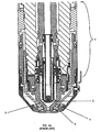
- a plasma arc torch generally includes a torch body 1, an electrode 2 mounted within the body, an insert 3 disposed within a bore of the electrode 2, a nozzle 4 with a central exit orifice, a shield 5, electrical connections (not shown), passages for cooling and arc control fluids, a swirl ring to control the fluid flow patterns, and a power supply (not shown).
- the torch produces a plasma arc, which is a constricted ionized jet of a plasma gas with high temperature and high momentum.
- a gas can be non-reactive, e.g. nitrogen or argon, or reactive, e.g. oxygen or air.
- a pilot arc is first generated between the electrode (cathode) and the nozzle (anode).
- the pilot arc ionizes gas that passes through the nozzle exit orifice. After the ionized gas reduces the electrical resistance between the electrode and the workpiece, the arc then transfers from the nozzle to the workpiece.
- the torch is operated in this transferred plasma arc mode, which is characterized by the conductive flow of ionized gas from the electrode to the workpiece, for the cutting, welding, or marking the workpiece.
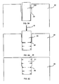
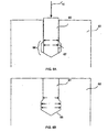
- FIGS. 1B-1D illustrate a known method for inserting and securing an insert into the bore of an electrode.
- FIG. 1B illustrates an insert 10 being pressed 15 into a bore in the end of an electrode body 12.
- FIG. 1C illustrates the secured insert 11 pressed 15 flush with the end surface 19 of the electrode body 12, and presents a diagrammatic representation of the resultant lateral forces securing the insert 11 in the electrode body 12. These resultant forces are thought to be greater near the exposed end of the insert due to surface friction from the expanding insert.
- Electrode bodies of the through-hole type 19 are also known to have linear-tapered walls, i.e., straight walls at an angle with a central longitudinal axis, with linear-tapered inserts shaped to match.
- the insert has an exterior, or exposed, end face, which defines an emissive surface area.
- the exterior surface of the insert is generally planar, and is manufactured to be coplanar with the end face of the electrode.
- the end face of the electrode is typically planar, although it can have exterior curved surfaces, e.g., edges. It is known to make the insert of hafnium or zirconium. They generally have a cylindrical shape. Insert materials (e.g., hafnium) can be expensive.
- US 5,767,478 describes an electrode for supporting an arc in a plasma arc torch.
- the electrode includes a metallic holder having a front end, and a cavity in said front end, the cavity having an enlarged outer end portion.
- An insert assembly is mounted in the cavity and includes an emissive insert composed of a metallic material having a relatively low work function, and a sleeve which surrounds at least a portion of said emissive insert so as to separate said portion of said emissive insert from contact with said holder.
- the sleeve is composed of a metal which is selected from the group consisting of silver, gold, platinum, rhodium, iridium, palladium, nickel, and alloys thereof.
- the metallic holder includes an overlay portion at said front end, said overlay portion directly contacting said emissive insert so that none of said sleeve is exposed at said front end.
- torch conditions such as temperature gradients and dynamics work to reduce the retention force holding the insert in place and either allow the insert to move in the bore or to fall completely out of the bore, thereby reducing the service life of the electrode or causing it to completely fail.
- the movement of the insert also indicates that the insert to electrode interface has degraded, which reduces the thermal and electrical conductivity of the interface and thereby the service life of the electrode as well.
- insert materials e.g., hafnium
- insert materials are poor thermal conductors for the removal of heat produced by the plasma arc, which can produce temperatures in excess of 10,000 degrees C. Insufficient removal of heat resulting from these high temperatures can result in a decrease in the service life of the electrode.
- a first object of the invention is to provide an electrode with improved retention of an insert, increasing the thermal conductivity of the interface between insert and electrode, and the efficiency and service life of the electrode. It is another object of the invention to provide an electrode with an insert configuration that improves the cooling, and therefore the service life, of the insert. It is yet another object of the invention to provide an electrode with an insert configuration that minimizes the amount of insert material required, thereby reducing the cost of the electrode while at the same time not lessening the efficiency and service life of the electrode. Yet another object of the invention is to provide an electrode with a longer service life.
- the present invention achieves these objectives by using electrode bore and/or insert configurations to establish retention forces located near an interior (e.g. a contact end or a central portion) of the insert or an interior (e.g., a closed end or a central portion) of the bore to secure the insert in the electrode.
- the present invention also allows the size of the insert to be minimized, thereby reducing insert raw material costs and improving electrode cooling.
- One aspect of the invention features an electrode for a plasma arc torch, the electrode including an electrode body formed of a high thermal conductivity material.
- the electrode body includes a first end and a second end defining a longitudinal axis.
- a bore is defined by and disposed in the first end of the electrode body.
- the bore includes a closed end and an open end.
- the bore defines at least a first and a second dimension each transverse to the longitudinal axis, wherein the second dimension is closer to the closed end of the bore than the first dimension.
- the electrode also includes an insert formed of a high thermionic emissivity material disposed in the bore.
- the insert includes an exterior end disposed near the open end of the bore and a contact end disposed near the closed end of the bore.
- the insert defines at least a first and a second dimension each transverse to the longitudinal axis, wherein the second dimension is closer to the closed end of the bore than the first dimension.
- the second dimension of the bore is greater than the first dimension of the bore, or the second dimension of the insert is greater than the first dimension of the insert.
- the electrode further comprises a sleeve disposed between the insert and the bore.
- the sleeve can be formed of a high emissivity material, e.g., hafnium or zirconium, or of a high thermal conductivity material, e.g., copper, a copper alloy, or silver.
- the sleeve is silver.
- the sleeve and the insert can be of different materials.
- the insert can be hafnium and the sleeve can be silver, or the insert can be silver and the sleeve can be hafnium.
- the second dimension can correspond to an annular notch.
- the bore can include two substantially cylindrical portions, wherein a portion defining the closed end has a diameter smaller than the diameter of the portion defining the open end of the bore.
- This discontinuity in diameters can define a step surface, e.g. a frustoconical surface step, which can be located anywhere along the length of the bore.
- a surface projection may be located between the two cylindrical portions, and can be located anywhere along the length of the bore.
- the surface projection can be one or more barbs, which may be at the same or different longitudinal depths, or an annular projection.
- the bore can alternatively include a substantially cylindrical portion defining a closed end and a frustoconical portion defining the open end.
- the bore may have the opposite configuration, i.e., a frustoconical portion defining a closed end and a cylindrical portion defining an open end.
- the bore includes two portions, wherein the portion defining the closed end has a diameter greater than a portion defining an open end of the bore.
- the insert is a substantially cylindrical insert with a diameter slightly less than the diameter of the open end portion of the bore.
- the diameter of the insert can be smaller than both diameters of the bore to provide a gap between the bore and the insert, such that the insert can easily fit in the bore when the insert is initially pressed into the bore.
- the gap between the insert and the electrode may be greater for the open-end cylindrical portion than the gap for the closed-end cylindrical portion.
- the diameter of the insert is formed to be the same as or virtually indistinguishable from the diameter of the closed-end cylindrical portion of the bore, and accordingly a gap between the insert and the bore around this portion can be small or nonexistent.
- the end surface of the bore may have any suitable shape and configuration.
- the end surface may be configured to mate with a contact end of the insert.
- the closed end surface of the bore can be planar surfaces.
- the contact end of the insert can be configured to mate with said planar surface.
- the closed end surface of the bore can include a tapered depression, e.g., formed by a drill point.
- the contact end of the insert can be configured to mate with said tapered depression.
- the insert can include a substantially cylindrical contact end and an elongated frustoconical exposed end.
- the insert can alternatively include two substantially cylindrical portions and a frustoconical portion located between the two other portions, wherein the contact end portion of the insert has a larger diameter than the exterior end portion of the insert.
- the insert can alternatively include an elongated frustoconical body, wherein a contact end has a larger diameter than an exterior end.
- the insert can alternatively include two substantially cylindrical portions with an annular notch located between the two portions. The notch can be formed around the insert to align with a step in the bore of the electrode body.
- the high thermionic emissivity material of the insert can be hafnium or zirconium, or tungsten, or thorium or lanthanum or strontium or alloys thereof.
- the high thermal conductivity material of the electrode body can be copper or a copper alloy.
- an electrode for a plasma arc torch including an electrode body formed of a high thermal conductivity material.
- the electrode body includes a first end and a second end defining a longitudinal axis.
- a bore is defined by and disposed in the first end of the electrode body.
- the bore includes a first portion, a second portion, and a third portion, wherein the first portion includes an outer open end of the bore and the third portion includes an inner open end of the bore.
- the second portion of the bore defines at least a first and a second dimension each transverse to the longitudinal axis, wherein the second dimension is closer to the third portion of the bore than the first dimension.
- the electrode also includes an insert formed of a high thermionic emissivity material disposed in the bore.
- the insert includes a first portion, a second portion, and a third portion.
- the first portion includes an exterior end disposed near the outer open end of the bore and the third portion includes an end disposed near the inner open end of the bore.
- the insert defines at least a first and a second dimension each transverse to the longitudinal axis, wherein the second dimension is closer to the third portion of the insert than the first dimension.
- the second dimension of the bore is greater than the first dimension of the bore, or the second dimension of the insert is greater than the first dimension of the insert.
- the electrode further comprises a sleeve disposed between the insert and the bore.
- the sleeve can be formed of a high emissivity material, e,g., hafnium or zirconium, or of a high thermal conductivity material, e.g., copper, a copper alloy, or silver.
- the sleeve is silver.
- the sleeve and the insert can be of different materials.
- the insert can be hafnium and the sleeve can be silver, or the insert can be silver and the sleeve can be hafnium.
- the second dimension can correspond to an annular notch.
- the bore can include two substantially cylindrical portions, wherein a portion defining the inner open end has a diameter smaller than the diameter of the portion defining the outer open end of the bore.
- This discontinuity in diameters can define a step surface, e.g. a frustoconical surface step, which can be located anywhere along the length of the bore.
- a surface projection may be located between the two cylindrical portions, and can be located anywhere along the length of the bore.
- the surface projection can be one or more barbs, which may be at the same or different longitudinal depths, or an annular projection.
- the bore can alternatively include a substantially cylindrical portion defining an inner open end and a frustoconical portion defining the outer open end.
- the bore may have the opposite configuration, i.e., a frustoconical portion defining an inner open end and a cylindrical portion defining an outer open end.
- the bore includes two portions, wherein the portion defining the inner open end has a diameter greater than a portion defining an outer open end of the bore.
- the insert is a substantially cylindrical insert with a diameter slightly less than the diameter of the outer open end portion of the bore.
- the diameter of the insert can be smaller than both diameters of the bore to provide a gap such that the insert can easily fit in the bore when the insert is initially pressed into the bore.
- the gap between the insert and the electrode may be greater for the outer open-end cylindrical portion than the gap for the inner open-end cylindrical portion.
- the diameter of the insert is formed to be the same as or virtually indistinguishable from the diameter of the inner open-end cylindrical portion of the bore, and accordingly a gap between the insert and the bore around this portion can be small or nonexistent,
- the insert can include a substantially cylindrical contact end and an elongated frustoconical exposed end.
- the insert can alternatively include two substantially cylindrical portions and a frustoconical portion located between the two other portions, wherein the contact end portion of the insert has a larger diameter than the exterior end portion of the insert.
- the insert can alternatively include an elongated frustoconical body, wherein a contact end has a larger diameter than an exterior end.
- the insert can alternatively include two substantially cylindrical portions with an annular notch located between the two portions. The notch can be formed around the insert to align with a step in the bore of the electrode body.
- the high thermionic emissivity material of the insert can be hafnium or zirconium, or tungsten, or thorium or lanthanum or strontium or alloys thereof.
- the high thermal conductivity material of the electrode body can be copper or a copper alloy.
- the electrode includes an electrode body formed of a high thermal conductivity material.
- the electrode body includes a first end and a second end defining a longitudinal axis.
- a bore is defined by and disposed in the first end of the electrode body.
- the bore includes a first end and a second end.
- the first end of the bore includes an open end of the bore.
- the electrode also includes an insert formed of a high thermionic emissivity material disposed in the bore.
- the insert has a longitudinal length and includes a first end portion, a second end portion, a first portion between the first and the second end portions, and a second portion between the first and the second end portions.
- the first end portion includes an exterior end surface disposed near the open end of the bore, and a longitudinal length of the first end portion being no more than about 10% of the longitudinal length of the insert.
- the second end portion includes a longitudinal length of the second end portion being no more than about 20% of the longitudinal length of the insert.
- the first portion defines a first dimension transverse to the longitudinal axis, and includes a first exterior surface.
- the second portion defines a second dimension transverse to the longitudinal axis and includes a second exterior surface, wherein the first dimension is greater than the second dimension.
- a first angle of a tangent to the first exterior surface with respect to the longitudinal axis and a second angle of a tangent to the second exterior surface with respect to the longitudinal axis differ by at least 3 degrees.
- the longitudinal length of the first end portion is no more than about 2% of the longitudinal length of the insert and/or the longitudinal length of the second end portion is no more than about 10% of the longitudinal length of the insert.
- the high thermionic emissivity material of the insert can be hafnium or zirconium, or tungsten, or thorium or lanthanum or strontium or alloys thereof.
- the high thermal conductivity material of the electrode body can be copper or a copper alloy.
- a central portion of the bore can include at least two substantially cylindrical portions.
- a central body portion of the insert can include at least two substantially cylindrical portions. At least one of a central portion of the bore and a central body portion of the insert can be substantially cylindrical.
- the bore can comprise an annular extension.
- the electrode body can include a cross-drilled hole, which can cross paths with a cylindrical bore.
- the cross-drilled hole is formed by drilling a hole from outside of the electrode into at least a portion of the bore. The drilling operation can be terminated after the bore is reached, i.e., without extending the hole to the far side of the electrode.
- Multiple cross-drilled holes can also be used in accordance with principles of the present invention, and these multiple holes can be at different points at different points along the longitudinal axis of the electrode, i.e., at different elevations.
- the insert can comprise a flared head.
- the insert can be a cylindrical insert with a flared head. Inserts can be sized to allow the insert to fit into the bore leaving enough insert material extending out of the bore to overfill the hole when pressed.
- the bore can include an annular extension around the open end of the bore. The annular extension can be uniformly symmetric about a center axis of the electrode body, but other configurations can also be used, e.g., a non-uniform extension, or series of extensions surrounding the open end of the bore.
- the electrode includes an electrode body formed of a high thermal conductivity material.
- the electrode body includes a first end and a second end defining a longitudinal axis.
- a bore is defined by and disposed in the first end of the electrode body.
- the bore includes an open end and a closed end.
- the electrode also includes an insert formed of a high thermionic emissivity material disposed in the bore.
- the insert comprises a first exterior surface exerting a first force against a first surface of the bore, and a second exterior surface exerting a second force against a second surface of the bore.
- the second force is greater than the first force, and the second surface of the bore is longitudinally closer to the closed end of the bore than the fust surface of the bore.
- the high thermionic emissivity material of the insert can be hafnium or zirconium, or tungsten, or thorium or lanthanum or strontium or alloys thereof. In some embodiments, the high thermionic emissivity material of the insert can be hafnium or zirconium.
- the high thermal conductivity material of the electrode body can be copper or a copper alloy.
- the electrode can further comprise a sleeve disposed between the insert and the electrode body.
- the sleeve can be formed of a high emissivity material, e.g., hafnium or zirconium, or of a high thermal conductivity material, e.g., copper, a copper alloy, or silver.
- the sleeve is silver.
- the sleeve and the insert can be of different materials.
- the insert can be hafnium and the sleeve can be silver, or the insert can be silver and the sleeve can be hafnium.
- the insert includes two substantially cylindrical portions and a frustoconical portion between the two other portions, wherein a contact end portion of the insert has a larger diameter than an exterior end portion of the insert.
- the sleeve can include a contact end configured to mate with the frustoconical portion such that as the sleeve is pressed into the insert, the surface of the insert contacts the contact end.
- the end surface of the bore can be a planar surface, but can have other configurations as well, e.g., a tapered depression, which mates with a contact end of an insert.
- a central portion of the bore can include at least two substantially cylindrical portions.
- a central body portion of the insert can include at least two substantially cylindrical portions. At least one of a central portion of the bore and a central body portion of the insert can be substantially cylindrical.
- the bore can comprise an annular extension.
- the electrode body can include a cross-drilled hole, which can cross paths with a cylindrical bore, In some embodiments, the cross-drilled hole is formed by drilling a hole from outside of the electrode into at least a portion of the bore. The drilling operation can be terminated after the bore is reached, i.e., without extending the hole to the far side of the electrode.
- Multiple cross-drilled holes can also be used in accordance with principles of the present invention, and these multiple holes can be at different points at different points along the longitudinal axis of the electrode, i.e., at different elevations.
- the insert can comprise a flared head.
- the insert can be a cylindrical insert with a flared head. Inserts can be sized to allow the insert to fit into the bore leaving enough insert material extending out of the bore to overfill the hole when pressed.
- the bore can include an annular extension around the open end of the bore. The annular extension can be uniformly symmetric about a center axis of the electrode body, but other configurations can also be used, e.g., a non-uniform extension, or series of extensions surrounding the open end of the bore.
- the electrode includes an electrode body formed of a high thermal conductivity material.
- the electrode body includes a first end and a second end defining a longitudinal axis.
- a bore is defined by and disposed in the first end of the electrode body.
- the bore includes a first portion, a second portion, and a third portion.
- the first portion defines an outer open end of the bore.
- the third portion defines an inner open end of the bore.
- the electrode also includes an insert formed of a high thermionic emissivity material disposed in the bore.
- the insert comprises a first exterior surface exerting a first force against a first surface of the second portion of the bore, and a second exterior surface exerting a second force against a second surface of the second portion of the bore.
- the second force is greater than the first force, and the second surface of the bore is longitudinally closer to the third portion of the bore than the first surface of the bore.
- the high thermionic emissivity material of the insert can be hafnium or zirconium, or tungsten, or thorium or lanthanum or strontium or alloys thereof. In some embodiments, the high thermionic emissivity material of the insert can be hafnium or zirconium.
- the high thermal conductivity material of the electrode body can be copper or a copper alloy.
- the electrode can further comprise a sleeve disposed between the insert and the electrode body.
- the sleeve can be formed of a high emissivity material, e.g., hafnium or zirconium, or of a high thermal conductivity material, e.g., copper, a copper alloy, or silver.
- the sleeve is silver.
- the sleeve and the insert can be of different materials.
- the insert can be hafnium and the sleeve can be silver, or the insert can be silver and the sleeve can be hafnium.
- the insert includes two substantially cylindrical portions and a frustoconical portion between the two other portions, wherein a contact end portion of the insert has a larger diameter than an exterior end portion of the insert.
- the sleeve can include a contact end configured to mate with the frustoconical portion such that as the sleeve is pressed into the insert, the surface of the insert contacts the contact end.
- a central portion of the bore can include at least two substantially cylindrical portions.
- a central body portion of the insert can Include at least two substantially cylindrical portions. At least one of a central portion of the bore and a central body portion of the insert can be substantially cylindrical.
- the bore can comprise an annular extension.
- the electrode body can include a cross-drilled hole, which can cross paths with a cylindrical bore.
- the cross-drilled hole is formed by drilling a hole from outside of the electrode into at least a portion of the bore. The drilling operation can be terminated after the bore is reached, i.e., without extending the hole to the far side of the electrode.
- Multiple cross-drilled holes can also be used in accordance with principles of the present invention, and these multiple holes can be at different points at different points along the longitudinal axis of the electrode, i.e., at different elevations.
- the insert can comprise a flared head.
- the insert can be a cylindrical insert with a flared head. Inserts can be sized to allow the insert to fit into the bore leaving enough insert material extending out of the bore to overfill the hole when pressed.
- the bore can include an annular extension around the open end of the bore. The annular extension can be uniformly symmetric about a center axis of the electrode body, but other configurations can also be used, e.g., a non-uniform extension, or series of extensions surrounding the open end of the bore.
- the electrode includes an electrode body formed of a high thermal conductivity material.
- the electrode body includes a first end and a second end defining a longitudinal axis.
- a bore is defined by and disposed in the first end of the electrode body.
- the bore includes an open end and a closed end.
- a projection is disposed on a surface of the bore.
- the surface of the bore is located away from the open end.
- the electrode also includes an insert formed of a high thermionic emissivity material disposed in the bore. A contact surface of the insert surrounds at least a portion of the projection to secure the insert in the bore.
- the projection can be disposed at or near the closed end of the bore, wherein the projection extends partially towards the open end.
- the projection can comprise barbs, grooves, or notches.
- the projection may be integrally formed with the electrode body, or integrally formed with the insert, (e.g. a preformed indentation formed at the bottom of the insert) or may be not integrally formed with the electrode body or the insert.
- the projection can be substantially symmetrical about the longitudinal axis.
- the contact surface can be a contact end of the insert.
- the bore can include a cylindrical portion.
- the insert may be a cylindrical insert with a diameter slightly less than the diameter of the bore.
- a contact end of the insert may comprise a bore, which can be configured to mate with the projection of the electrode bore, such that before the insert can be completely pressed flush with the bore of the electrode body, a surface of the projection can contact the insert.
- the projection can be centered and symmetric about a center axis of the electrode body, but other configurations can also be used, e.g., a tapered wall aligned along a diameter of the bore, or one or more tapered projections emanating from the walls of the bore.
- the projection is not integrally formed with the electrode body or the insert.
- the electrode comprises an insert object, e.g., a spherical object, square shavings placed in the bore, and/or one or more other shapes/objects.
- the insert object e.g., ball
- the insert object can be placed into the bore of the electrode body prior to the insertion of the insert.
- the insert object e.g. ball
- the insert object can be formed of a material, e.g., steel, which is harder than the material of the insert.
- the high thermionic emissivity material of the insert can be hafnium or zirconium, or tungsten, or thorium or lanthanum or strontium or alloys thereof.
- the high thermal conductivity material of the electrode body can be copper or a copper alloy.
- Another aspect of the invention features a method for fabricating an electrode having an emissive insert for use in plasma arc torches.
- the method includes the step of forming an electrode body of a high thermal conductivity material, wherein the electrode body includes a first end and a second end defining a longitudinal axis.
- a bore is formed in the first end, wherein the bore includes a first portion and a second portion.
- An insert formed, of a high thermionic emissivity material is positioned in the bore, the insert including a contact end and an exterior end.
- the contact end of the insert is aligned with the second portion of the bore, and the exterior end is aligned with the first portion of the bore, such that a first gap is established between a first exterior surface of the insert and the first portion, and a second gap is established between a second exterior surface of the insert and the second portion of the bore.
- the first gap is substantially greater than the second gap.
- a force is applied at the exterior end of the insert to secure the insert in the bore.
- the bore can further comprise a third portion defining a second open end of the bore, wherein the second portion of the bore is located between the first and third portions of the bore.
- the second portion of the bore can define a closed end of the bore.
- the first gap can be nearer the open end of the bore than the second gap.
- the first gap can be nearer the closed end/second portion of the bore than the second gap.
- the applied force can be a longitudinal force applied at the exterior end of the insert that reduces the gap.
- the applied force can be a compressive force that compresses the open end of the bore about the insert.
- the method can further comprise the step of positioning a sleeve formed of a second material in the bore before the force can be applied, wherein the first gap can be disposed between a surface of the sleeve and the first exterior surface of the insert.
- the high thermionic emissivity material of the insert can be hafnium or zirconium, or tungsten, or thorium or lanthanum or strontium or alloys thereof.
- the high thermal conductivity material of the electrode body can be copper or a copper alloy.
- a plasma arc torch including a torch body, a nozzle within the torch body, a shield disposed adjacent the nozzle, and an electrode mounted relative to the nozzle in the torch body to define a plasma chamber.
- the shield protects the nozzle from workpiece splatter.
- the electrode comprises an electrode body formed of a high thermal conductivity material.
- the electrode body includes a first end and a second end defining a longitudinal axis.
- a bore is defined by and disposed in the first end of the electrode body.
- the bore includes a closed end and an open end.
- the bore defines at least a first and a second dimension each transverse to the longitudinal axis, wherein the second dimension is closer to the closed end of the bore than the first dimension.
- the electrode also includes an insert formed of a high thermionic emissivity material disposed in the bore.
- the insert includes an exterior end disposed near the open end of the bore and a contact end disposed near the closed end of the bore.
- the insert defines at least a first and a second dimension each transverse to the longitudinal axis, wherein the second dimension is closer to the closed end of the bore than the first dimension.
- the second dimension of the bore is greater than the first dimension of the bore, or the second dimension of the insert is greater than the first dimension of the insert.
- the high thermionic emissivity material of the insert can be hafnium or zirconium, or tungsten, or thorium or lanthanum or strontium or alloys thereof.
- the high thermal conductivity material of the electrode body can be copper or a copper alloy.
- FIG. 1A is a partial cross-sectional view of a known plasma arc torch
- FIG. 1B is a partial cross-sectional view of a plasma arc torch electrode illustrating a known method for inserting an insert into an electrode bore;
- FIG. 1C is a partial cross-sectional view of a plasma arc torch electrode illustrating a known method for securing an insert into an electrode bore;
- FIG. 1D is a partial cross-sectional view of a plasma arc torch electrode illustrating a known method for securing an insert into an electrode bore with a through-hole configuration
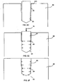
- FIGS. 2A-2C are partial cross-sectional views of a plasma arc torch electrode configuration illustrating intermediate steps of a method for securing an insert into an electrode bore incorporating principles of the present invention
- FIGS. 2D-2F are partial cross-sectional views of a plasma arc torch electrode configuration illustrating intermediate steps of a method for securing an insert into an electrode bore incorporating principles of the present invention
- FIGS. 3A-3C are partial cross-sectional views of different plasma arc torch electrode bore configurations
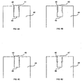
- FIGS. 4A-4D are partial cross-sectional views of plasma arc torch electrode and insert configurations
- FIGS. 5A-5F are partial cross-sectional views of plasma arc torch insert configurations
- FIG. 6A is a partial cross-sectional view of a plasma arc torch electrode configuration illustrating a method for securing an insert into an electrode bore;
- FIG. 6B is a partial cross-sectional view of a plasma arc torch electrode configuration comprising an insert secured in the electrode bore;
- FIG. 6C is a partial cross-sectional view of a plasma arc torch electrode configuration comprising an insert secured in the electrode bore with a through-hole configuration;
- FIG. 7 is another partial cross-sectional view of a plasma arc torch electrode and insert configuration comprising a projection in the bore of the electrode;
- FIG. 8 is a partial cross-sectional view of a plasma arc torch electrode and insert configuration comprising an insert sleeve
- FIG. 9 is a partial cross-sectional view of plasma arc torch electrode and insert configuration comprising an insert ball
- FIG. 10 is a partial cross-sectional view of plasma arc torch electrode and insert configuration comprising a cross-drilled hole
- FIGS. 11A-11B are partial cross-sectional view of a plasma arc torch electrode and insert configurations
- FIG. 12A is a partial cross-sectional view of a plasma arc torch electrode configuration illustrating a method for securing an insert into an electrode bore;
- FIG. 12B is a partial cross-sectional view of a plasma arc torch electrode configuration having an insert secured in an electrode bore according to the method of FIG. 12A ;
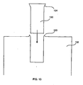
- FIG. 13 is a partial cross-sectional view of a plasma arc torch electrode configuration comprising an annular lip and an insert configuration comprising a flared head configuration;
- FIGS. 14A-14B are partial cross-sectional views illustrating a method of forming an electrode incorporating principles of the present invention.
- FIGS. 15A-15B are partial cross-sectional views illustrating central portions of inserts disposed in electrodes.
- FIGS. 2A-2B illustrate an exemplary method for securing an insert into an electrode bore and the resulting electrode configuration incorporating principles of the present invention.
- the electrode body 22 comprises a bore in which an insert is to be secured.
- the bore can include two substantially cylindrical portions, wherein a portion defining the closed end has a diameter smaller than the portion defining the open end of the bore. This discontinuity in diameters can define a step surface 26, which can be located anywhere along the length of the bore.
- a substantially cylindrical insert 20 with a diameter slightly less than the diameter of the closed end portion of the bore is illustrated.
- FIG, 2A illustrates an initial configuration of the electrode after a substantially cylindrical insert 200 has been placed in the bore of electrode body 22.
- the diameter of the insert can be smaller than both diameters of the bore to provide a gap such that the insert 200 can easily fit in the bore.
- the gap between the insert 200 and the electrode 22 is greater for the open-end cylindrical portion than the gap for the closed-end cylindrical portion.
- a gap between the insert and the bore around this portion can be small or nonexistent.
- FIG. 2B illustrates an intermediate configuration of the electrode after the insert 20 has been pressed 15 into the closed end portion of the bore and presents a diagrammatic representation of the initial resultant lateral forces present between the sidewalls of the insert 20 and the electrode body 22.
- FIG. 2C illustrates a final configuration of the secured insert 21 and presents a diagrammatic representation of the resultant lateral retention forces between the sidewalls of the insert 21 and the electrode body 22.
- the initial clearance between the open end portion of the bore and the insert results in the formation of a radial bulge deeper in the bore than in the prior art case illustrated in FIG. 1C , because of the absence of surface friction at said open end.
- the retention forces are greatest near the step surface 26, which are advantageously located away from the exposed portion 24 of the insert 21 to which the plasma arc attaches during torch operation. Thus, this portion of greatest retention strength is kept cooler and is less prone to erosion.
- FIGS. 2D-2F illustrate another embodiment of the invention, somewhat similar to those illustrated in FIGS. 2A-2C , except that the closed end surface 23 of the bore can include a tapered depression, e.g., formed by a drill point, with which the contact end of the insert 27 can be configured to mate.
- the end surface 23 of the bore can have other configurations as well, which mate with a contact end of an insert in accordance with principles of the present invention. Similar principles can also be used with a through-hole configuration, in which case an inner open end would replace the closed end surface 23 in the representation in FIGS. 2D-2F .
- FIGS. 3A-3C are partial cross-sectional illustrations of embodiments of a plasma arc torch electrode bore configuration. More specifically, FIG. 3A illustrates an electrode body 32 comprising a bore with two substantially cylindrical portions, wherein the portion defining the closed end has a smaller diameter than the portion defining the open end of the electrode body 32. A frustoconical surface step 36 is illustrated between the two cylindrical portions and can be located anywhere along the length of the bore. FIG. 3B illustrates an electrode body 33 comprising a bore with two substantially cylindrical portions, wherein the portion defining the closed end has a smaller diameter than the portion defining the open end of the electrode body 33. A surface projection 37 can be located between the two cylindrical portions, and can be located anywhere along the length of the bore.
- FIG. 3C illustrates an electrode body 34 comprising a bore with a substantially cylindrical portion 36 defining a closed end and a frustoconical portion 38 defining the open end.
- a bore with the opposite configuration, i.e., a frustoconical portion defining a closed end and a cylindrical portion defining an open end, can be provided as another embodiment or configuration.
- the electrode embodiments illustrated in FIGS. 3A-3C can each have a gap, as illustrated in Fig. 2A , with respect to an insert when the insert is initially pressed into the bore.
- a radial bulge can be formed away from the open end of the bore, resulting in the retention forces being greatest around this bulge and the insert being secured in the electrode body.
- the end surfaces 39 of the bore can be planar surfaces, but they can have other configurations as well, e.g., a tapered depression, which can mate with a contact end of an insert. Similar principles can also be used in a through-hole configuration, in which case an inner open end would be replace the closed end surface 39 in the representation in FIGS. 3A-3C .
- FIGS. 4A-4D are partial cross-sectional illustrations of intermediate plasma arc torch electrode and insert configurations.
- FIG. 4A illustrates an electrode body 42 comprising a substantially cylindrical bore.
- the insert can include a substantially cylindrical contact end 49 and an elongated frustoconical exposed end 41.
- FIG. 4B illustrates an electrode body 44 comprising a substantially cylindrical bore.
- the insert 43 can include two substantially cylindrical portions and a frustoconical portion located between the two other portions, wherein the contact end portion of the insert 43 has a larger diameter than the exterior end portion of the insert 43.
- FIG. 4C illustrates another embodiment including an electrode body 46 comprising a substantially cylindrical bore.
- the insert can include an elongated frustoconical body, wherein a contact end 49 has a larger diameter than an exterior end 45.
- FIG. 4D illustrates an electrode body 48 comprising a bore, which can include two substantially cylindrical portions similar to electrode 22 of FIG. 2A .
- the insert 47 can include two substantially cylindrical portions with an annular notch located between the two portions. The notch can be formed around the insert to align with a step in the bore of the electrode body 48.
- the electrode and insert embodiments illustrated in FIGS. 4A-4D each have a gap 40 when the insert is initially pressed into the bore. Thus, a radial bulge can form away from an open end of the bore, causing the retention force to be greatest around this bulge, thereby securing the insert in the electrode body.
- the end surfaces 49 of the bore can be planar surfaces, but they can have other configurations as well, e.g., a tapered depression, which mate with a contact end of an insert. Similar principles can also be used in a through-hole configuration, in which case an inner open end would replace the closed end surface 49 in the representation in FIGS. 4A-4D .
- the electrodes 42, 44, 46, and 48 comprise cylindrical bores, but they can have other configurations as well, e.g., the electrode configurations 22, 32, 33, and 34, in accordance with principles of the present invention,
- the bore and insert diameters, lengths, and tapers illustrated in FIGS. 3A-3C and 4A-4D can all be modified, e.g., the tapers could be straight, convex or concave, and they can have multiple steps or tapers in combination, all in accordance with principles of the present invention.
- FIGS. 5A-5F are partial cross-sectional illustrations of embodiments of a plasma arc torch insert configuration in accordance with embodiments of the invention.
- FIG. 5A illustrates an insert with a notched head and an elongated taper lead out.
- FIG. 5B illustrates an insert with a notched or grooved 51 head.
- FIG. 5C illustrates an insert with a notched or grooved 51 head and a spherical end surface.
- FIG. 5D illustrates an insert with a notched head and with a smaller diameter lower cylindrical portion.
- FIG. 5E illustrates an insert with multiple notches or grooves.
- FIG. 5F illustrates an insert with an external projection 52 that can mate with a surface of an electrode bore, e.g., step surface 26.
- FIGS. 5A-5E illustrate annular notches or grooves on an insert, they can also have notches or grooves that are not annular, e.g., one or more barbs, which can be located at different longitudinal positions.
- the surface roughness of the insert and/or the bore can also be configured to provide a roughness to enhance insert retention. For example, small grooves in the surfaces of the bore and/or insert, or even threadlike patterns, can be used to enhance surface retention.
- all insert contact surface geometries e.g., planar, spherical, conical end surfaces, can be used with any of the insert configurations illustrated in FIGS. 5A-5F , or their respective through-hole configurations, in accordance with principles of the present invention.
- FIGS. 6A-6B illustrate another embodiment of a method and apparatus for securing an insert into an electrode bore, and the resulting electrode configuration.
- the electrode body 62 comprises a bore in which an insert is to be secured.
- the bore can include two portions, wherein the portion defining a closed end 66 has a diameter greater than a portion defining an open end of the bore.
- a substantially cylindrical insert 60 with a diameter slightly less than the diameter of the open end portion of the bore is illustrated.
- FIG. 6A illustrates an intermediate configuration of the electrode after the insert 60 has been pressed 15 into the closed end portion of the bore and presents a diagrammatic representation of the initial resultant lateral forces present in the insert 60.
- FIG. 6B illustrates a final configuration of a secured insert 61 and presents a diagrammatic representation of the resultant lateral retention forces between the sidewalls of the insert 61 and the electrode body 62.
- the end surface of the bore can be a tapered depression, but other configurations can also be used, e.g., a planar surface, which can mate with a contact end of an insert FIG.
- FIGS. 6A-6B illustrates another configuration of a secured insert 63 in an electrode with a through-hole configuration, inserted and secured in a similar fashion as illustrated in FIGS. 6A-6B .
- the absence of a side surface in the central portion 64 allows the insert to expand at this depth, resulting in increased retention forces at this portion of the electrode body 68.
- FIG. 7 is a partial cross-sectional view of another embodiment of an intermediate plasma arc torch electrode and insert configuration.
- the electrode body 72 comprises a bore in which an insert is to be secured.
- the bore can include a cylindrical portion and a projection 73, e.g., disposed on the closed end surface of the bore.
- a cylindrical insert 71 with a diameter slightly less than the diameter of the bore is provided.
- a contact end of the insert 71 comprises a bore 74.
- the bore 74 of the insert 71 can be configured to mate with a projection 73 of the electrode bore such that before the insert 71 can be completely pressed flush with the bore of the electrode body 72, a surface 75 of the projection can contact the insert 71.
- the imperfect matching of the insert 71 and the electrode body 72 configurations can force the insert 71 to expand outwardly into the electrode body 72, resulting in increased retention forces at this portion of the electrode body 72.
- the location of these forces at this position in the electrode are advantageously located away from the exposed portion of the insert 71 to which the plasma arc attaches during torch operation.
- this portion of the insert experiences increased retention strength, is kept cooler, and is less prone to erosion.
- the projection in this embodiment can be centered and symmetric about a center axis of the electrode body, but other configurations can also be used, e.g., a tapered wall aligned along a diameter of the bore, or one or more tapered projections emanating from the walls of the bore, in accordance with principles of the present invention.
- FIG. 8 is a partial cross-sectional view of an intermediate plasma arc torch electrode and insert configuration.
- the electrode body 82 comprises a cylindrical bore in which an insert is to be secured.
- the insert 81 can include two substantially cylindrical portions and a frustoconical portion 83 illustrated between the two other portions, similar to insert 43, wherein a contact end portion of the insert 81 has a larger diameter than an exterior end portion of the insert 81.
- a sleeve 84 is provided and can be configured for insertion between the insert 81 and the bore of the electrode body 82.
- the sleeve 84 can include a contact end 85 configured to mate with the frustoconical portion 83 such that as the sleeve 84 is pressed into the insert 81, the surface 83 of the insert 81 contacts the contact end 85.
- the imperfect matching of the insert 81 and the sleeve 84 configurations force the sleeve 84 to expand outwardly into the electrode body 82, resulting in an increase in the retention forces at this portion of the electrode body 82 and, in effect, "crimping" or securing the insert 81 into the bore of the electrode body 82.
- the sleeve can be formed of a high emissivity material, e,g., hafnium or zirconium, or of a high thermal conductivity material, e.g., copper, a copper alloy, or silver,
- the sleeve and the insert can be of different materials.
- the insert can be hafnium and the sleeve can be silver, or the insert can be silver and the sleeve can be hafnium.
- the end surface of the bore can be a planar surface, but can have other configurations as well, e.g., a tapered depression, which mate with a contact end of an insert. Similar principles can also be used with a through-hole electrode configuration, in which case the closed end surface represented in FIG. 8 would be replaced with an inner open end.
- the insert can be supported by an anvil or mandrel at the inner open end of the electrode body.
- FIG. 9 is a partial cross-sectional view of an embodiment of an intermediate plasma arc torch electrode and insert configuration comprising an insert object, e.g., a spherical object.
- the electrode body 92 comprises a cylindrical bore.
- a substantially cylindrical insert 91 with a diameter slightly less than the diameter of the bore is provided.
- a ball 95 can be placed into the bore of the electrode body 92 prior to the insertion of the insert 91.
- the ball 95 can be formed of a material, e.g., steel, which is harder than the material of the insert.
- the hard surface of the ball 95 can cause a contact end of the insert 91 to expand outwardly, thereby securing the insert in the bore of the electrode body 92.
- the ball 95 thus can perform a function similar to the projection 73 illustrated in FIG. 7 .
- a preformed indentation can be formed at the bottom of the insert, square shavings can be placed in the bore, and/or one or more other shapes/objects in place of the ball 95.
- FIG. 10 is a partial cross-sectional view of plasma arc torch electrode and insert configuration comprising a cross-drilled hole.
- the electrode body 102 can include a cross-drilled hole 105, which can cross paths with a cylindrical bore.
- the cross-drilled hole is formed by drilling a hole from outside of the electrode into at least a portion of the bore. The drilling operation can be terminated after the bore is reached, i.e., without extending the hole to the far side of the electrode. Of course, other configurations can be used.
- a substantially cylindrical insert 101 with a diameter slightly less than the diameter of the bore is provided.
- the cross-drilled hole 105 can provide two areas of unrestricted expansions for the insert 101, such that upon insertion of the insert 101 into the bore, the insert 101 can expand 106 into the cross-drilled hole 105. Said expansion thus can secure the insert 101 in the bore of the electrode body 102.
- Multiple cross-drilled holes can also be used in accordance with principles of the present invention, and these multiple holes can be at different points at different points along the longitudinal axis of the electrode, i.e., at different elevations.
- FIGS. 11A-11B are partial cross-sectional views of other embodiments of intermediate plasma arc torch electrode and insert configurations.
- the electrode body 112 comprises a cylindrical bore in which an insert is to be secured.
- a substantially cylindrical insert 111 with a diameter slightly less than the diameter of the bore is provided.
- the contact end of the insert 111 can include a countersunk surface 115.
- FIG. 11A illustrates an intermediate configuration of the electrode as the insert 111 is being pressed into the bore.
- FIG. 11B illustrates a second intermediate configuration of the electrode as the insert 111 is pressed against the end surface of the bore and presents a diagrammatic representation of the initial resultant lateral forces present between the sidewalls of the insert 111 and the electrode body 112.
- the contact end of the insert expands radially outwardly into the bore, securing the insert.
- the retention forces can be increased near the end surface of the bore, which is advantageously located away from the exposed portion of the insert 111 to which the plasma arc attaches during torch operation.
- this portion of increased retention strength is kept cooler and is less prone to erosion.
- FIGS. 12A-12B illustrate a method for securing an insert into an electrode bore, and the resulting electrode configuration.
- the electrode body 122 comprises a cylindrical bore in which an insert is to be secured.
- An elongated tapered insert 120 is provided, wherein a contact end 128 can have a larger diameter than the exterior end 129.
- FIG. 12A illustrates an intermediate configuration of the electrode after the insert 120 has been pressed into the closed end portion of the bore. It also presents a diagrammatic representation of lateral forces 120 applied on and around an end portion of the electrode body to secure the insert. These forces can be applied to an external surface of the electrode body.
- the resulting forces 120 are directed radially inwards and can force the electrode body 122 to at least partially conform to the insert 121.
- FIG. 12B illustrates a final configuration of the secured insert 121 in the electrode body 123. In this manner, the hoop strength at the compressed end of the electrode body 123 secures the insert 121.
- FIG. 13 is a partial cross-sectional view of an intermediate plasma arc torch electrode and insert configuration.
- the electrode body 132 comprises a cylindrical bore.
- the bore can include an annular extension 133 around the open end of the bore.
- a cylindrical insert 130 with a flared head 131 is provided. Inserts can be sized to allow the insert to fit into the bore leaving enough insert material extending out of the bore to overfill the hole when pressed.
- the flared head 131 of the insert 130 can be a different configuration for providing additional insert material.
- the flared head 131 can also ensure that after the insert 130 has been press fit into the bore of the electrode body 132 no air gap exists around the exposed end of the insert 130 between the insert and the side walls of the bore, which can degrade the thermal cooling of the electrode insert.
- the annular extension 133 in this embodiment can be uniformly symmetric about a center axis of the electrode body, but other configurations can also be used, e.g., a non-uniform extension, or series of extensions surrounding the open end of the bore, in accordance with principles of the present invention. While the electrode illustrated in FIG. 13 is one particular embodiment, the extension 133 can be used with other electrode embodiments, e.g., electrodes 22, 29, 32, 33, 34, 42, 44, 46, 48, 62, 68, 72, 92, and 112 of FIGS. 2A , 2D , 3A-3C , 4A-4D , 6A , 6C , 7 , 9 , and 11A , in accordance with principles of the present invention. The extension 133 can be used with inserts that do or do not include a flared head 131.
- FIGS. 14A-14B are partial cross-sectional views illustrating a method of forming an electrode incorporating principles of the present invention.
- a first portion 141 of the electrode body can be provided with a closed-ended cylindrical bore having a first diameter D1.
- a second portion 142 of the electrode body can be provided with an open-ended cylindrical bore having a second diameter D2 greater than the first diameter.
- FIG. 14A illustrates a method of solid state welding, e.g., friction welding 140 the second portion 142 to the first portion 141.
- the diameter D1 of the first portion 141 is greater than the diameter D2 of the second portion 142.
- FIG. 14B illustrates a final configuration of the electrode body of FIG.
- the first and second portions can be formed of a high thermal conductivity material, such as copper, copper alloy, or silver.
- the second portion can be formed from the same or different material from that of the first portion.
- the electrode illustrated in FIG. 14B is one particular embodiment, the same method can be used to form other electrode embodiments, e,g., electrodes 29, 32, 33, 34, 62, and 72 of FIGS. 2D , 3A-3C , 6A , and 7 , in accordance with principles of the present invention. Similar principles as those illustrated in FIGS. 12A-12B , 13 , and 14A-14B can also be used in respective or combined through-hole configurations, in which case an open end surface would be replace the closed end surface of the electrode body illustrated.
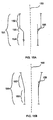
- FIGS. 15A-15B are partial cross-sectional views illustrating central portions of inserts disposed in electrodes.
- FIG. 15A illustrates a final configuration of a central portion of an insert 151 secured in an electrode body (not shown).
- the central portion of the insert 151 can have a longitudinal length of no less than about 70% of the longitudinal length of the insert.
- the central portion of the insert 151 can include a first portion 152, a second portion 153, and a third portion 154.
- the first portion 152, second portion 153, and third portion 154 can each define an angle relative to the longitudinal axis 150 of the insert and a tangent to their respective exterior surfaces. For example, as illustrated in FIG.
- the angle 155 defined between the longitudinal axis 150 and a tangent to an exterior surface of the second portion 153 is greater than 0 degrees.
- the angle defined between the longitudinal axis 150 and a tangent to an exterior surface of either the first portion 152 or the third portion 154 is zero, because the first portion 152 and the third portion 154 are cylindrical.
- FIG. 15B illustrates a different final configuration of a central portion of an insert 156 secured in an electrode body (not shown).
- the central portion of the insert 156 can include a first portion 157, and a second portion 158.
- the first portion 157, and second portion 158 can each define an angle relative to the longitudinal axis 150 of the insert and a tangent to their respective exterior surfaces.
- the angle 159 defined between the longitudinal axis 150 and a tangent to an exterior surface of the first portion 157 is greater than 0 degrees.
- the angle defined between the longitudinal axis 150 and a tangent to an exterior surface of the second portion 158 is zero, because the second portion 158 is cylindrical.
- the angles defined by the tangents to the exterior surfaces of the insert and the longitudinal axis of the insert differ by at least 1 degree. In another embodiment, the angles defined by the tangents to the exterior surfaces of the insert and the longitudinal axis of the insert differ by at least 3 degrees. While the secured central portions of inserts 151 and 156 illustrated in FIGS. 15A and 15B are two particular embodiments, the same minimum angle differentiation between different central portions of an insert can be used with other insert embodiments, e.g., inserts 21, 28, 41, 43, 45, 47, 61, 62, 63, 71, 81, 91, 101, 111, 121, and 130, of FIGS.
- one or more exterior surfaces of the insert can be disposed at a constant or continuously varying tangential angle relative to the longitudinal axis.
- the exterior surfaces can also be non-uniform, e.g., about a perimeter of a cross section of the insert.
- next parts tested used the same 0.052" counter-bore, but the deeper hole (e.g., the inner hole that extended to ⁇ 0.100" in overall depth) was increased to a 0.0465" diameter.
- One set of parts that was tested had the 0.052" diameter counter-bore drilled to a depth of 0.030", with the smaller diameter hole drilled to a depth of 0.090".
- the next set of parts tested were drilled to 0.050" (larger diameter) and 0.095" (smaller diameter).
- the same 120437 insert described above was used, producing the following results based on three samples each. 0.030" depth Average 20 second starts: 181.7 Standard deviation: 12.2 0.050" depth Average 20 second starts: 240.3 Standard deviation: 37.1
- the used parts indicated in Table 1 were run for 50, twenty second starts. These parts were not modified in accordance with principles of the invention. In every case tested, the used parts required a lower force to remove the insert. The used stock parts produced the highest standard deviation and the lowest push out force, sometimes requiring only 6 pounds of force to dislodge the emissive insert. As indicated in Table 2, the two best stepped hole designs required a minimum of 45 and 54 pounds to remove the insert. These results for the used parts were also more consistent, as indicated by the reduced standard deviation of the sample results.
- Embodiments of the invention also include a method for forming an electrode body of a high thermal conductivity material. Steps of the method, as partially described above in FIGS. 2A-2F and 6A-6C , include forming the electrode body to include a first end and a second end defining a longitudinal axis. A bore is formed in the first end, such that the bore includes a first portion and a second portion. An insert formed of a high thermionic emissivity material is positioned in the bore, wherein the insert includes a contact end and an exterior end.
- the contact end of the insert is aligned with the second portion of the bore, and the exterior end is aligned with the first portion of the bore, such that a first gap is established between a first exterior surface of the insert and the first portion, and a second gap is established between a second exterior surface of the insert and the second portion of the bore.
- the first gap is substantially greater than the second gap.
- a force is applied at the exterior end of the insert to secure the insert in the bore.
- Embodiments of the invention also include a method for optimizing the combination of insert emissive area and insert volume, thereby reducing the cost o the insert material while maintaining a high quality emissive area.
- each electrode body embodiment described or illustrated herein can be formed from a high thermal conductivity material, e.g., copper, a copper alloy, or silver. It is also to be understood that each electrode body embodiment also represents the situation in which the bore illustrated is formed in a sleeve, either before or after the sleeve can be inserted into a larger bore in the electrode body.
- the sleeve can be formed from a high thermal conductivity material, e.g., copper, a copper alloy, or silver, or from a high thermionic emissivity material, e.g., hafnium or any material the insert can be formed of.
- the insert in each embodiment described or illustrated herein can be formed from a high thermionic emissivity material, e.g., hafnium, zirconium, tungsten, thorium, lanthanum, strontium, or alloys thereof.
- a high thermionic emissivity material e.g., hafnium, zirconium, tungsten, thorium, lanthanum, strontium, or alloys thereof.
- the invention provides an electrode with improved retention of an insert, thereby increasing the thermal conductivity of the interface between insert and electrode, and the efficiency and service life of the electrode.
- the invention also provides an electrode with an insert configuration that improves the cooling, and therefore the service life, of the insert.
- the invention also provides an electrode with an insert configuration that minimizes the amount of insert material required, thereby reducing the cost of the electrode while at the same time not lessening the efficiency and service life of the electrode.
- the invention also provides an electrode with a longer service life.
Landscapes
- Physics & Mathematics (AREA)
- Engineering & Computer Science (AREA)
- Plasma & Fusion (AREA)
- Spectroscopy & Molecular Physics (AREA)
- Plasma Technology (AREA)
- Arc Welding In General (AREA)
Claims (39)
- Elektrode für einen Plasmalichtbogenbrenner, wobei die Elektrode aufweist:einen Elektrodenkörper (68), der aus einem Werkstoff mit einer hohen Wärmeleitfähigkeit gebildet ist, wobei der Elektrodenkörper ein erstes Ende und ein zweites Ende und eine Längsachse hat;eine Bohrung, die von dem Elektrodenkörper begrenzt und in dem ersten Ende des Elektrodenkörpers angeordnet ist, wobei die Bohrung einen ersten Abschnitt, einen zweiten Abschnitt (64) und einen dritten Abschnitt hat, wobei der erste Abschnitt ein äußeres offenes Ende der Bohrung enthält, der dritte Abschnitt ein inneres offenes Ende der Bohrung enthält, der zweite Abschnitt der Bohrung mindestens ein erstes und ein zweites Maß hat, die jeweils quer zu der Längsachse sind, wobei das zweite Maß näher an dem dritten Abschnitt der Bohrung als das erste Maß ist; undeinen Einsatz (63), der aus einem Werkstoff mit einem hohen thermionischen Emissionsvermögen gebildet und in der Bohrung angeordnet ist, wobei der Einsatz einen ersten Teil, einen zweiten Teil und einen dritten Teil aufweist, wobei der erste Teil ein äußeres Ende hat, das in der Nähe des äußeren offenen Endes der Bohrung angeordnet ist, der dritte Teil ein Ende hat, das in der Nähe des inneren offenen Endes der Bohrung angeordnet ist, wobei der Einsatz mindestens ein erstes und ein zweites Maß hat, die jeweils quer zu der Längsachse sind, wobei das zweite Maß näher an dem dritten Teil des Einsatzes als das erste Maß ist;wobei die Elektrode eines oder beides davon erfüllt, dass:(a) das zweite Maß der Bohrung größer als das erste Maß der Bohrung ist, und(b) das zweite Maß des Einsatzes größer als das erste Maß des Einsatzes ist.
- Elektrode für einen Plasmalichtbogenbrenner, wobei die Elektrode aufweist:einen Elektrodenkörper (42, 44, 46, 48, 62, 82, 102, 122, 123), der aus einem Werkstoff mit einer hohen Wärmeleitfähigkeit gebildet ist, wobei der Elektrodenkörper ein erstes Ende und ein zweites Ende und eine Längsachse hat;eine Bohrung, die von dem Elektrodenkörper begrenzt und in dem ersten Ende des Elektrodenkörpers angeordnet ist, wobei die Bohrung ein geschlossenes Ende und ein offenes Ende hat, wobei die Bohrung mindestens ein erstes und ein zweites Maß hat, die jeweils quer zu der Längsachse sind, wobei das zweite Maß (66, 105) näher an dem geschlossenen Ende der Bohrung als das erste Maß ist; undeinen Einsatz (43, 47, 60, 61, 81, 101, 121), der aus einem Werkstoff mit einem hohen thermionischen Emissionsvermögen gebildet und in der Bohrung angeordnet ist, wobei der Einsatz ein äußeres Ende (41, 45), das in der Nähe des offenen Endes der Bohrung angeordnet ist, und ein Kontaktende (49, 128), das in der Nähe des geschlossenen Endes der Bohrung angeordnet ist, hat, wobei der Einsatz mindestens ein erstes und ein zweites Maß hat, die jeweils quer zu der Längsachse sind, wobei das zweite Maß näher an dem geschlossenen Ende der Bohrung als das erste Maß ist;dadurch gekennzeichnet, dass die Elektrode eines oder beides davon erfüllt, dass(a) das zweite Maß (66, 105) der Bohrung größer als das erste Maß der Bohrung ist, und(b) das zweite Maß (49, 128) des Einsatzes größer als das erste Maß (41, 45) des Einsatzes ist.
- Elektrode nach Anspruch 1 oder Anspruch 2, wobei die Elektrode ferner eine Hülse (84) aufweist, die zwischen dem Einsatz und der Bohrung angeordnet ist.
- Elektrode nach irgend einem der Ansprüche 1 bis 3, wobei das zweite Maß einer ringförmigen Kerbe (51) entspricht.
- Elektrode für einen Plasmalichtbogenbrenner, wobei die Elektrode aufweist:einen Elektrodenkörper (22, 29, 32, 33, 34, 42, 44, 46, 48, 62, 68, 82, 102, 112), der aus einem Werkstoff mit einer hohen Wärmeleitfähigkeit gebildet ist, wobei der Elektrodenkörper ein erstes Ende und ein zweites Ende und eine Längsachse hat;eine Bohrung, die von dem Elektrodenkörper begrenzt und in dem ersten Ende des Elektrodenkörpers angeordnet ist, wobei die Bohrung ein erstes und ein zweites Ende hat, wobei das erste Ende der Bohrung ein offenes Ende der Bohrung hat; undeinen Einsatz (21, 28, 43, 47, 61, 64, 81, 101, 121, 151, 156), der aus einem Werkstoff mit einem hohen thermionischen Emissionsvermögen gebildet und in der Bohrung angeordnet ist, wobei der Einsatz eine längsgerichtete Länge hat,dadurch gekennzeichnet, dass der Einsatz aufweisteinen ersten Endteil, der eine äußere Endfläche hat, die in der Nähe des offenen Endes der Bohrung angeordnet ist, wobei eine längsgerichtete Länge des ersten Endteils nicht mehr als ungefähr 10% der längsgerichteten Länge des Einsatzes beträgt;einen zweiten Endteil, wobei eine längsgerichtete Länge des zweiten Endteils nicht mehr als ungefähr 20% der längsgerichteten Länge des Einsatzes beträgt;einen ersten Teil (152, 153, 157) zwischen dem ersten und dem zweiten Endteil, wobei der erste Teil ein erstes Maß hat, das quer zu der Längsachse ist, wobei der erste Teil eine erste äußere Fläche hat;einen zweiten Teil (153, 154, 158) zwischen dem ersten und dem zweiten Endteil, wobei der zweite Teil ein zweites Maß hat, das quer zu der Längsachse ist und eine zweite äußere Fläche hat, wobei das erste Maß größer als das zweite Maß ist; undwobei ein erster Winkel einer Tangente an der ersten äußeren Fläche, bezogen auf die Längsachse, und ein zweiter Winkel einer Tangente an der zweiten äußeren Fläche, bezogen auf die Längsachse, sich um mindestens 3 Grad unterscheiden.
- Elektrode nach Anspruch 5, wobei die längsgerichtete Länge des ersten Endteils nicht mehr als ungefähr 2% der längsgerichteten Länge des Einsatzes beträgt.
- Elektrode nach Anspruch 5 oder Anspruch 6, wobei die längsgerichtete Länge des zweiten Endteils nicht mehr als ungefähr 10% der längsgerichteten Länge des Einsatzes beträgt.
- Elektrode nach irgend einem der Ansprüche 5 bis 7, wobei der ein hohes thermionisches Emissionsvermögen aufweisende Werkstoff des Einsatzes Hafnium oder Zirkonium oder Wolfram oder Thorium oder Lanthan oder Strontium oder eine Legierung daraus ist.
- Elektrode nach irgend einem der Ansprüche 5 bis 8, wobei der eine hohe Wärmeleitfähigkeit aufweisende Werkstoff des Elektrodenkörpers Kupfer oder eine Kupferlegierung ist.
- Elektrode für einen Plasmalichtbogenbrenner, wobei die Elektrode aufweist:einen Elektrodenkörper (22, 29, 32, 33, 34, 42, 44, 46, 48, 62, 82), der aus einem Werkstoff mit einer hohen Wärmeleitfähigkeit gebildet ist, wobei der Elektrodenkörper ein erstes Ende und ein zweites Ende und eine Längsachse hat;eine Bohrung, die von dem Elektrodenkörper begrenzt und in dem ersten Ende des Elektrodenkörpers angeordnet ist, wobei die Bohrung ein offenes Ende und ein geschlossenes Ende (23) hat; undeinen Einsatz (21, 28, 43, 47, 66, 81), der aus einem Werkstoff mit einem hohen thermionischen Emissionsvermögen gebildet und in der Bohrung angeordnet ist,dadurch gekennzeichnet, dass der Einsatz aufweist:eine erste äußere Fläche, die eine erste Kraft auf eine erste Fläche der Bohrung ausübt; undeine zweite äußere Fläche, die eine zweite Kraft auf eine zweite Fläche der Bohrung ausübt, wobei die zweite Kraft größer als die erste Kraft ist und wobei die zweite Fläche der Bohrung in Längsrichtung näher an dem geschlossenen Ende der Bohrung als die erste Fläche der Bohrung ist.
- Elektrode nach Anspruch 10, wobei der ein hohes thermionisches Emissionsvermögen aufweisende Werkstoff des Einsatzes Hafnium oder Zirkonium ist.
- Elektrode nach Anspruch 10 oder Anspruch 11, wobei der eine hohe Wärmeleitfähigkeit aufweisende Werkstoff des Elektrodenkörpers Kupfer oder eine Kupferlegierung ist.
- Elektrode nach irgend einem der Ansprüche 10 bis 12, wobei die Elektrode ferner eine Hülse (84) aufweist, die zwischen dem Einsatz und dem Elektrodenkörper angeordnet ist.
- Elektrode nach Anspruch 13, wobei die Hülse aus Silber ist.
- Elektrode für einen Plasmalichtbogenbrenner, wobei die Elektrode aufweist:einen Elektrodenkörper (68), der aus einem Werkstoff mit einer hohen Wärmeleitfähigkeit gebildet ist, wobei der Elektrodenkörper ein erstes Ende und ein zweites Ende und eine Längsachse hat;eine Bohrung, die von dem Elektrodenkörper begrenzt und in dem ersten Ende des Elektrodenkörpers angeordnet ist, wobei die Bohrung einen ersten Abschnitt, einen zweiten Abschnitt (64) und einen dritten Abschnitt aufweist, wobei der erste Abschnitt ein äußeres offenes Ende der Bohrung hat, der dritte Abschnitt ein inneres offenes Ende der Bohrung hat; undeinen Einsatz (63), der aus einem Werkstoff mit einem hohen thermionischen Emissionsvermögen gebildet und in der Bohrung angeordnet ist,wobei der Einsatz aufweist:eine erste äußere Fläche, die eine erste Kraft auf eine erste Fläche des zweiten Abschnittes der Bohrung ausübt; undeine zweite äußere Fläche, die eine zweite Kraft auf eine zweite Fläche des zweiten Abschnittes der Bohrung ausübt, wobei die zweite Kraft größer als die erste Kraft ist, wobei die zweite Fläche der Bohrung in Längsrichtung näher an dem dritten Abschnitt der Bohrung als die erste Fläche der Bohrung ist.
- Elektrode nach Anspruch 15, wobei der ein hohes thermionisches Emissionsvermögen aufweisende Werkstoff des Einsatzes Hafnium oder Zirkonium ist.
- Elektrode nach Anspruch 15 oder Anspruch 16, wobei der eine hohe Wärmeleitfähigkeit aufweisende Werkstoff des Elektrodenkörpers Kupfer oder eine Kupferlegierung ist.
- Elektrode nach irgend einem der Ansprüche 15 bis 17, wobei die Elektrode ferner eine Hülse (84) aufweist, die zwischen dem Einsatz und dem Elektrodenkörper angeordnet ist.
- Elektrode nach Anspruch 18, wobei die Hülse aus Silber ist.
- Elektrode nach irgend einem der Ansprüche 5 bis 19, wobei ein mittlerer Abschnitt der Bohrung mindestens zwei im Wesentlichen zylindrische Abschnitte aufweist.
- Elektrode nach irgend einem der Ansprüche 5 bis 20, wobei ein mittlerer Körperteil des Einsatzes mindestens zwei im Wesentlichen zylindrische Teile aufweist.
- Elektrode nach irgend einem der Ansprüche 5 bis 21, wobei mindestens der mittlere Abschnitt der Bohrung oder der mittlere Körperteil des Einsatzes im Wesentlichen zylindrisch ist.
- Elektrode nach irgend einem der Ansprüche 5 bis 22, wobei die Bohrung eine ringförmige Verlängerung (133) aufweist.
- Elektrode nach irgend einem der Ansprüche 5 bis 23, wobei der Einsatz einen konisch erweiterten Kopf (131) aufweist.
- Elektrode für einen Plasmalichtbogenbrenner, wobei die Elektrode aufweist:einen Elektrodenkörper (72, 92), der aus einem Werkstoff mit einer hohen Wärmeleitfähigkeit gebildet ist, wobei der Elektrodenkörper ein erstes Ende und ein zweites Ende und eine Längsachse aufweist;eine Bohrung, die von dem Elektrodenkörper begrenzt und in dem ersten Ende des Elektrodenkörpers angeordnet ist, wobei die Bohrung ein offenes Ende und ein geschlossenes Ende hat; undeinen Einsatz (71, 91), der aus einem Werkstoff mit einem hohen thermionischen Emissionsvermögen gebildet und in der Bohrung angeordnet ist;dadurch gekennzeichnet, dass die Elektrode einen Vorsprung (73, 95) aufweist, der an einer Fläche der Bohrung angeordnet ist, wobei die Fläche der Bohrung fern von dem offenen Ende angeordnet ist; wobei eine Kontaktfläche (74) des Einsatzes mindestens einen Teil des Vorsprungs umgibt, um den Einsatz in der Bohrung festzuhalten.
- Elektrode nach Anspruch 25, wobei der Vorsprung an dem oder in der Nähe des geschlossenen Endes der Bohrung angeordnet ist, wobei sich der Vorsprung teilweise in Richtung auf das offene Ende erstreckt.
- Elektrode nach Anspruch 25 oder Anspruch 26, wobei der Vorsprung Stacheln, Rillen oder Kerben aufweist.
- Elektrode nach irgend einem der Ansprüche 25 bis 27, wobei der Vorsprung nicht einstückig mit dem Elektrodenkörper oder dem Einsatz ausgebildet ist.
- Elektrode nach irgend einem der Ansprüche 25 bis 28, wobei der Vorsprung im Wesentlichen symmetrisch um die Längsachse ist.
- Elektrode nach irgend einem der Ansprüche 25 bis 29, wobei die Kontaktfläche ein Kontaktende des Einsatzes ist.
- Verfahren zum Herstellen einer Elektrode mit einem emittierenden Einsatz zur Verwendung in Plasmalichtbogenbrennern, wobei das Verfahren die folgenden Schritte aufweist:Bilden eines Elektrodenkörpers (22, 29, 32, 33, 34, 42, 44, 46, 48) aus einem Werkstoff mit einer hohen Wärmeleitfähigkeit, wobei der Elektrodenkörper ein erstes Ende und ein zweites Ende und eine Längsachse hat;Bilden einer Bohrung in dem ersten Ende, wobei die Bohrung einen ersten Abschnitt und einen zweiten Abschnitt hat;Anordnen eines Einsatzes (20, 27, 200, 270, 43, 47, 151, 156), der aus einem Werkstoff mit einem hohen thermionischen Emissionsvermögen gebildet ist, in der Bohrung, wobei der Einsatz ein Kontaktende und ein äußeres Ende hat;dadurch gekennzeichnet, dass das Verfahren umfasst:Ausrichten des Kontaktendes des Einsatzes zu dem zweiten Abschnitt der Bohrung und des äußeren Endes zu dem ersten Abschnitt der Bohrung derart, dass ein erster Spalt (40) zwischen einer ersten äußeren Fläche des Einsatzes und dem ersten Abschnitt gebildet wird, und ein zweiter Spalt zwischen einer zweiten äußeren Fläche des Einsatzes und dem zweiten Abschnitt der Bohrung gebildet wird, derart, dass der erste Spalt wesentlich größer als der zweite Spalt ist; undAufbringen einer Kraft an dem äußeren Ende des Einsatzes, um den Einsatz in der Bohrung festzuhalten.
- Verfahren nach Anspruch 31, wobei die Bohrung ferner einen dritten Abschnitt aufweist, der ein zweites offenes Ende der Bohrung hat, wobei der zweite Abschnitt der Bohrung zwischen dem ersten und dem dritten Abschnitt der Bohrung angeordnet ist.
- Verfahren nach Anspruch 31, wobei der zweite Abschnitt der Bohrung ein geschlossenes Ende der Bohrung hat.
- Verfahren nach irgend einem der Ansprüche 31 bis 33, wobei der erste Spalt näher an dem offenen Ende der Bohrung als der zweite Spalt ist.
- Verfahren nach irgend einem der Ansprüche 31 bis 33, wobei der erste Spalt näher an dem geschlossenen Ende /zweiten Abschnitt der Bohrung als der zweite Spalt ist.
- Verfahren nach irgend einem der Ansprüche 31 bis 35, wobei die aufgebrachte Kraft eine Längskraft ist, die auf das äußere Ende des Einsatzes aufgebracht wird und den Spalt verringert.
- Verfahren nach irgend einem der Ansprüche 31 bis 35, wobei die aufgebrachte Kraft eine Druckkraft ist, die das offene Ende der Bohrung um den Einsatz herum zusammendrückt.
- Verfahren nach irgend einem der Ansprüche 31 bis 37, ferner mit dem Schritt des Anordnens einer aus einem zweiten Werkstoff gebildeten Hülse (84) in der Bohrung, bevor die Kraft aufgebracht wird, und wobei der erste Spalt zwischen einer Fläche der Hülse und der ersten äußeren Fläche des Einsatzes angeordnet ist.
- Plasmalichtbogenbrenner mit:einem Brennergehäuse (1);einer Düse (4) in dem Brennergehäuse;einem Schirm (5), der angrenzend an die Düse angeordnet ist, wobei der Schild die Düse vor Werkstücksprztzern schützt;einer Elektrode (2), die bezüglich der Düse in dem Brennergehäuse angebracht ist, um eine Plasmakammer zu bilden, wobei die Elektrode in Einklang mit Anspruch 2 ist.
Applications Claiming Priority (2)
| Application Number | Priority Date | Filing Date | Title |
|---|---|---|---|
| US71458105P | 2005-09-07 | 2005-09-07 | |
| US11/468,393 US8101882B2 (en) | 2005-09-07 | 2006-08-30 | Plasma torch electrode with improved insert configurations |
Publications (3)
| Publication Number | Publication Date |
|---|---|
| EP1765046A1 EP1765046A1 (de) | 2007-03-21 |
| EP1765046B1 true EP1765046B1 (de) | 2010-08-25 |
| EP1765046B2 EP1765046B2 (de) | 2015-09-02 |
Family
ID=37398690
Family Applications (1)
| Application Number | Title | Priority Date | Filing Date |
|---|---|---|---|
| EP06254615.5A Active EP1765046B2 (de) | 2005-09-07 | 2006-09-05 | Elektrode für Plasmabrenner mit einer verbesserten Einsatzanlage |
Country Status (8)
| Country | Link |
|---|---|
| US (1) | US8101882B2 (de) |
| EP (1) | EP1765046B2 (de) |
| KR (1) | KR20080041731A (de) |
| AT (1) | ATE479318T1 (de) |
| BR (1) | BRPI0615685A2 (de) |
| CA (1) | CA2621918A1 (de) |
| DE (1) | DE602006016385D1 (de) |
| WO (1) | WO2007030420A1 (de) |
Cited By (2)
| Publication number | Priority date | Publication date | Assignee | Title |
|---|---|---|---|---|
| EP2642831A1 (de) | 2012-03-22 | 2013-09-25 | Hollberg, Manfred | Plasma-Elektrode für einen Plasma-Lichtbogenbrenner und Verfahren zur Herstellung |
| EP2642832A1 (de) | 2012-03-23 | 2013-09-25 | Manfred Hollberg | Plasma-Elektrode für einen Plasmalichtbogenbrenner mit auswechselbarer Elektrodenspitze |
Families Citing this family (33)
| Publication number | Priority date | Publication date | Assignee | Title |
|---|---|---|---|---|
| DE102008062731C5 (de) | 2008-12-18 | 2012-06-14 | Kjellberg Finsterwalde Plasma Und Maschinen Gmbh | Elektrode für einen Plasmabrenner |
| TWI409119B (zh) * | 2009-07-30 | 2013-09-21 | Nippon Steel & Sumikin Welding | 嵌入式晶片、電漿火炬及電漿加工裝置 |
| US8395070B2 (en) | 2010-04-01 | 2013-03-12 | American Torch Tip | Electrical contact point device for use in a plasma arc cutting torch |
| US8680426B2 (en) | 2011-02-28 | 2014-03-25 | Thermal Dynamics Corporation | High current electrode for a plasma arc torch |
| USD692402S1 (en) * | 2012-03-08 | 2013-10-29 | Hypertherm, Inc. | Plasma torch electrode |
| US8525069B1 (en) * | 2012-05-18 | 2013-09-03 | Hypertherm, Inc. | Method and apparatus for improved cutting life of a plasma arc torch |
| ES2707292T3 (es) * | 2012-05-24 | 2019-04-03 | Kjellberg Stiftung | Electrodo para soplete de corte por chorro de plasma, así como su uso |
| US9949356B2 (en) * | 2012-07-11 | 2018-04-17 | Lincoln Global, Inc. | Electrode for a plasma arc cutting torch |
| EP2804450B1 (de) * | 2013-05-16 | 2022-05-04 | Kjellberg-Stiftung | Mehrteiliges Isolierteil für einen Lichtbogenplasmabrenner, Brenner und zugehörige Anordnungen mit demselben und zugehörigen Verfahren |
| ITBO20130302A1 (it) * | 2013-06-14 | 2014-12-15 | Tec Mo S R L | Metodo per la realizzazione di un elettrodo per torcia al plasma ed elettrodo cosi' ottenuto |
| US9338872B2 (en) | 2013-07-31 | 2016-05-10 | Lincoln Global, Inc. | Apparatus and method of aligning and securing components of a liquid cooled plasma arc torch |
| US9386679B2 (en) | 2013-07-31 | 2016-07-05 | Lincoln Global, Inc. | Apparatus and method of aligning and securing components of a liquid cooled plasma arc torch using a multi-thread connection |
| US9313871B2 (en) | 2013-07-31 | 2016-04-12 | Lincoln Global, Inc. | Apparatus and method of aligning and securing components of a liquid cooled plasma arc torch and improved torch design |
| US9878386B2 (en) * | 2013-10-31 | 2018-01-30 | Foundation Of Soongsil University-Industry Cooperation | Eccentric electrode for electric discharge machining, method of manufacturing the same, and micro electric discharge machining apparatus including the same |
| US9560733B2 (en) | 2014-02-24 | 2017-01-31 | Lincoln Global, Inc. | Nozzle throat for thermal processing and torch equipment |
| US9398679B2 (en) | 2014-05-19 | 2016-07-19 | Lincoln Global, Inc. | Air cooled plasma torch and components thereof |
| US9572242B2 (en) | 2014-05-19 | 2017-02-14 | Lincoln Global, Inc. | Air cooled plasma torch and components thereof |
| US9572243B2 (en) | 2014-05-19 | 2017-02-14 | Lincoln Global, Inc. | Air cooled plasma torch and components thereof |
| US9681528B2 (en) | 2014-08-21 | 2017-06-13 | Lincoln Global, Inc. | Rotatable plasma cutting torch assembly with short connections |
| US9730307B2 (en) * | 2014-08-21 | 2017-08-08 | Lincoln Global, Inc. | Multi-component electrode for a plasma cutting torch and torch including the same |
| US9736917B2 (en) | 2014-08-21 | 2017-08-15 | Lincoln Global, Inc. | Rotatable plasma cutting torch assembly with short connections |
| US9686848B2 (en) | 2014-09-25 | 2017-06-20 | Lincoln Global, Inc. | Plasma cutting torch, nozzle and shield cap |
| US9457419B2 (en) | 2014-09-25 | 2016-10-04 | Lincoln Global, Inc. | Plasma cutting torch, nozzle and shield cap |
| DE102015101532A1 (de) * | 2015-02-03 | 2016-08-04 | Kjellberg Stiftung | Düse für Plasmalichtbogenbrenner |
| US10863610B2 (en) | 2015-08-28 | 2020-12-08 | Lincoln Global, Inc. | Plasma torch and components thereof |
| DE102016010341B4 (de) | 2015-08-28 | 2024-08-01 | Lincoln Global, Inc. | Plasmabrenner und komponenten des plasmabrenners |
| US10639748B2 (en) | 2017-02-24 | 2020-05-05 | Lincoln Global, Inc. | Brazed electrode for plasma cutting torch |
| US10616988B2 (en) | 2017-06-20 | 2020-04-07 | The Esab Group Inc. | Electromechanical linearly actuated electrode |
| US10589373B2 (en) | 2017-07-10 | 2020-03-17 | Lincoln Global, Inc. | Vented plasma cutting electrode and torch using the same |
| USD861758S1 (en) | 2017-07-10 | 2019-10-01 | Lincoln Global, Inc. | Vented plasma cutting electrode |
| CA3121550A1 (en) * | 2018-11-30 | 2020-06-04 | Oerlikon Metco (Us) Inc. | Electrode for a plasma gun |
| US11678428B2 (en) | 2019-08-02 | 2023-06-13 | The Esab Group, Inc. | Method of assembling an electrode |
| TR202106962A2 (tr) * | 2021-04-21 | 2021-06-21 | Yildirim Ahmet | Plazma kesme torçlari i̇çi̇n yayici kesi̇ci̇ ucun (eki̇n) elektrot gövdesi̇ne bağlandiği yüzeyleri̇ni̇n yüzey arttirimiyla yapilmiş elektrot |
Family Cites Families (19)
| Publication number | Priority date | Publication date | Assignee | Title |
|---|---|---|---|---|
| US3408518A (en) * | 1966-10-03 | 1968-10-29 | Strupczewski Andrzej | Composite cathode for use in an arc plasma torch |
| US5396043A (en) * | 1988-06-07 | 1995-03-07 | Hypertherm, Inc. | Plasma arc cutting process and apparatus using an oxygen-rich gas shield |
| US4864097A (en) * | 1988-09-23 | 1989-09-05 | Emerson Electric Co. | Plasma arc torch with confined and controlled plasma jet column |
| FR2650470B1 (de) * | 1989-07-28 | 1992-09-04 | Soudure Autogene Francaise | |
| US5097111A (en) * | 1990-01-17 | 1992-03-17 | Esab Welding Products, Inc. | Electrode for plasma arc torch and method of fabricating same |
| US5023425A (en) † | 1990-01-17 | 1991-06-11 | Esab Welding Products, Inc. | Electrode for plasma arc torch and method of fabricating same |
| US5105061A (en) * | 1991-02-15 | 1992-04-14 | The Lincoln Electric Company | Vented electrode for a plasma torch |
| US5756959A (en) * | 1996-10-28 | 1998-05-26 | Hypertherm, Inc. | Coolant tube for use in a liquid-cooled electrode disposed in a plasma arc torch |
| US5676864A (en) * | 1997-01-02 | 1997-10-14 | American Torch Tip Company | Electrode for plasma arc torch |
| US5767478A (en) * | 1997-01-02 | 1998-06-16 | American Torch Tip Company | Electrode for plasma arc torch |
| AU9477598A (en) * | 1997-09-10 | 1999-03-29 | Esab Group, Inc., The | Electrode with emissive element having conductive portions |
| US6130399A (en) * | 1998-07-20 | 2000-10-10 | Hypertherm, Inc. | Electrode for a plasma arc torch having an improved insert configuration |
| US6020572A (en) * | 1998-08-12 | 2000-02-01 | The Esab Group, Inc. | Electrode for plasma arc torch and method of making same |
| US6177647B1 (en) * | 1999-04-29 | 2001-01-23 | Tatras, Inc. | Electrode for plasma arc torch and method of fabrication |
| US6424082B1 (en) * | 2000-08-03 | 2002-07-23 | Hypertherm, Inc. | Apparatus and method of improved consumable alignment in material processing apparatus |
| EP1202614B1 (de) | 2000-10-24 | 2012-02-29 | The Esab Group, Inc. | Elektrode mit hartgelötetem Abscheider |
| US6329627B1 (en) * | 2000-10-26 | 2001-12-11 | American Torch Tip Company | Electrode for plasma arc torch and method of making the same |
| WO2002074023A2 (en) * | 2001-03-09 | 2002-09-19 | Hypertherm, Inc. | Composite electrode for a plasma arc torch |
| DE10210421B4 (de) * | 2002-03-06 | 2007-11-22 | Fraunhofer-Gesellschaft zur Förderung der angewandten Forschung e.V. | Elektrodenelement für Plasmabrenner sowie Verfahren zur Herstellung |
-
2006
- 2006-08-30 US US11/468,393 patent/US8101882B2/en active Active
- 2006-09-05 EP EP06254615.5A patent/EP1765046B2/de active Active
- 2006-09-05 DE DE602006016385T patent/DE602006016385D1/de active Active
- 2006-09-05 AT AT06254615T patent/ATE479318T1/de not_active IP Right Cessation
- 2006-09-05 CA CA002621918A patent/CA2621918A1/en not_active Abandoned
- 2006-09-05 WO PCT/US2006/034444 patent/WO2007030420A1/en not_active Ceased
- 2006-09-05 BR BRPI0615685-1A patent/BRPI0615685A2/pt not_active Application Discontinuation
- 2006-09-05 KR KR1020087007777A patent/KR20080041731A/ko not_active Withdrawn
Cited By (4)
| Publication number | Priority date | Publication date | Assignee | Title |
|---|---|---|---|---|
| EP2642831A1 (de) | 2012-03-22 | 2013-09-25 | Hollberg, Manfred | Plasma-Elektrode für einen Plasma-Lichtbogenbrenner und Verfahren zur Herstellung |
| EP2642832A1 (de) | 2012-03-23 | 2013-09-25 | Manfred Hollberg | Plasma-Elektrode für einen Plasmalichtbogenbrenner mit auswechselbarer Elektrodenspitze |
| WO2013139484A1 (de) | 2012-03-23 | 2013-09-26 | Manfred Hollberg | Plasmaelektrode für einen plasma-lichtbogenbrenner mit auswechselbarer elektrodenspitze |
| US9736916B2 (en) | 2012-03-23 | 2017-08-15 | Manfred Hollberg | Plasma electrode for a plasma arc torch with replaceable electrode tip |
Also Published As
| Publication number | Publication date |
|---|---|
| EP1765046B2 (de) | 2015-09-02 |
| BRPI0615685A2 (pt) | 2011-05-24 |
| EP1765046A1 (de) | 2007-03-21 |
| DE602006016385D1 (de) | 2010-10-07 |
| US20080272094A9 (en) | 2008-11-06 |
| ATE479318T1 (de) | 2010-09-15 |
| WO2007030420A1 (en) | 2007-03-15 |
| US8101882B2 (en) | 2012-01-24 |
| US20070125755A1 (en) | 2007-06-07 |
| CA2621918A1 (en) | 2007-03-15 |
| KR20080041731A (ko) | 2008-05-13 |
Similar Documents
| Publication | Publication Date | Title |
|---|---|---|
| EP1765046B1 (de) | Elektrode für Plasmabrenner mit einer verbesserten Einsatzanlage | |
| US6114650A (en) | Electrode for plasma arc torch and method of making same | |
| AU2007217815B2 (en) | Electrode for a contact start plasma arc torch and contact start plasma arc torch employing such electrodes | |
| RU2659803C2 (ru) | Способ и устройство повышения эксплуатационного ресурса плазменно-дуговой горелки | |
| EP1099360B1 (de) | Elektrode für einen lichtbogen-plasmabrenner mit einem einsatz mit verbesserter konfiguration | |
| US5601734A (en) | Electrode for a plasma arc torch | |
| EP2801244B2 (de) | Bestandteil für einen kontaktstart-lichtbogenplasmabrenner | |
| US6686559B1 (en) | Electrode for plasma arc torch and method of making the same | |
| US6329627B1 (en) | Electrode for plasma arc torch and method of making the same | |
| KR100490611B1 (ko) | 플라즈마 아크 토치용 전극 | |
| KR100499656B1 (ko) | 전극 형성 방법 | |
| US6657153B2 (en) | Electrode diffusion bonding | |
| RU2239532C1 (ru) | Электрод для плазменной обработки | |
| KR200201855Y1 (ko) | 금속절단용 플라즈마 아크토치전극의 구조 |
Legal Events
| Date | Code | Title | Description |
|---|---|---|---|
| PUAI | Public reference made under article 153(3) epc to a published international application that has entered the european phase |
Free format text: ORIGINAL CODE: 0009012 |
|
| 17P | Request for examination filed |
Effective date: 20060922 |
|
| AK | Designated contracting states |
Kind code of ref document: A1 Designated state(s): AT BE BG CH CY CZ DE DK EE ES FI FR GB GR HU IE IS IT LI LT LU LV MC NL PL PT RO SE SI SK TR |
|
| AX | Request for extension of the european patent |
Extension state: AL BA HR MK YU |
|
| AKX | Designation fees paid |
Designated state(s): AT BE BG CH CY CZ DE DK EE ES FI FR GB GR HU IE IS IT LI LT LU LV MC NL PL PT RO SE SI SK TR |
|
| 17Q | First examination report despatched |
Effective date: 20080221 |
|
| GRAP | Despatch of communication of intention to grant a patent |
Free format text: ORIGINAL CODE: EPIDOSNIGR1 |
|
| GRAS | Grant fee paid |
Free format text: ORIGINAL CODE: EPIDOSNIGR3 |
|
| GRAA | (expected) grant |
Free format text: ORIGINAL CODE: 0009210 |
|
| AK | Designated contracting states |
Kind code of ref document: B1 Designated state(s): AT BE BG CH CY CZ DE DK EE ES FI FR GB GR HU IE IS IT LI LT LU LV MC NL PL PT RO SE SI SK TR |
|
| REG | Reference to a national code |
Ref country code: GB Ref legal event code: FG4D |
|
| REG | Reference to a national code |
Ref country code: CH Ref legal event code: NV Representative=s name: KIRKER & CIE S.A. Ref country code: CH Ref legal event code: EP |
|
| REG | Reference to a national code |
Ref country code: IE Ref legal event code: FG4D |
|
| REF | Corresponds to: |
Ref document number: 602006016385 Country of ref document: DE Date of ref document: 20101007 Kind code of ref document: P |
|
| REG | Reference to a national code |
Ref country code: NL Ref legal event code: VDEP Effective date: 20100825 |
|
| LTIE | Lt: invalidation of european patent or patent extension |
Effective date: 20100825 |
|
| PG25 | Lapsed in a contracting state [announced via postgrant information from national office to epo] |
Ref country code: AT Free format text: LAPSE BECAUSE OF FAILURE TO SUBMIT A TRANSLATION OF THE DESCRIPTION OR TO PAY THE FEE WITHIN THE PRESCRIBED TIME-LIMIT Effective date: 20100825 Ref country code: LT Free format text: LAPSE BECAUSE OF FAILURE TO SUBMIT A TRANSLATION OF THE DESCRIPTION OR TO PAY THE FEE WITHIN THE PRESCRIBED TIME-LIMIT Effective date: 20100825 Ref country code: FI Free format text: LAPSE BECAUSE OF FAILURE TO SUBMIT A TRANSLATION OF THE DESCRIPTION OR TO PAY THE FEE WITHIN THE PRESCRIBED TIME-LIMIT Effective date: 20100825 |
|
| PLBI | Opposition filed |
Free format text: ORIGINAL CODE: 0009260 |
|
| PG25 | Lapsed in a contracting state [announced via postgrant information from national office to epo] |
Ref country code: BG Free format text: LAPSE BECAUSE OF FAILURE TO SUBMIT A TRANSLATION OF THE DESCRIPTION OR TO PAY THE FEE WITHIN THE PRESCRIBED TIME-LIMIT Effective date: 20101125 Ref country code: SI Free format text: LAPSE BECAUSE OF FAILURE TO SUBMIT A TRANSLATION OF THE DESCRIPTION OR TO PAY THE FEE WITHIN THE PRESCRIBED TIME-LIMIT Effective date: 20100825 Ref country code: PT Free format text: LAPSE BECAUSE OF FAILURE TO SUBMIT A TRANSLATION OF THE DESCRIPTION OR TO PAY THE FEE WITHIN THE PRESCRIBED TIME-LIMIT Effective date: 20101227 Ref country code: PL Free format text: LAPSE BECAUSE OF FAILURE TO SUBMIT A TRANSLATION OF THE DESCRIPTION OR TO PAY THE FEE WITHIN THE PRESCRIBED TIME-LIMIT Effective date: 20100825 Ref country code: IS Free format text: LAPSE BECAUSE OF FAILURE TO SUBMIT A TRANSLATION OF THE DESCRIPTION OR TO PAY THE FEE WITHIN THE PRESCRIBED TIME-LIMIT Effective date: 20101225 Ref country code: CY Free format text: LAPSE BECAUSE OF FAILURE TO SUBMIT A TRANSLATION OF THE DESCRIPTION OR TO PAY THE FEE WITHIN THE PRESCRIBED TIME-LIMIT Effective date: 20100825 |
|
| 26 | Opposition filed |
Opponent name: L'AIR LIQUIDE, SOCIETE ANONYME POUR L Effective date: 20110209 |
|
| PG25 | Lapsed in a contracting state [announced via postgrant information from national office to epo] |
Ref country code: GR Free format text: LAPSE BECAUSE OF FAILURE TO SUBMIT A TRANSLATION OF THE DESCRIPTION OR TO PAY THE FEE WITHIN THE PRESCRIBED TIME-LIMIT Effective date: 20101126 Ref country code: NL Free format text: LAPSE BECAUSE OF FAILURE TO SUBMIT A TRANSLATION OF THE DESCRIPTION OR TO PAY THE FEE WITHIN THE PRESCRIBED TIME-LIMIT Effective date: 20100825 Ref country code: LV Free format text: LAPSE BECAUSE OF FAILURE TO SUBMIT A TRANSLATION OF THE DESCRIPTION OR TO PAY THE FEE WITHIN THE PRESCRIBED TIME-LIMIT Effective date: 20100825 Ref country code: BE Free format text: LAPSE BECAUSE OF FAILURE TO SUBMIT A TRANSLATION OF THE DESCRIPTION OR TO PAY THE FEE WITHIN THE PRESCRIBED TIME-LIMIT Effective date: 20100825 Ref country code: SE Free format text: LAPSE BECAUSE OF FAILURE TO SUBMIT A TRANSLATION OF THE DESCRIPTION OR TO PAY THE FEE WITHIN THE PRESCRIBED TIME-LIMIT Effective date: 20100825 |
|
| REG | Reference to a national code |
Ref country code: DE Ref legal event code: R026 Ref document number: 602006016385 Country of ref document: DE Effective date: 20110209 |
|
| PG25 | Lapsed in a contracting state [announced via postgrant information from national office to epo] |
Ref country code: DK Free format text: LAPSE BECAUSE OF FAILURE TO SUBMIT A TRANSLATION OF THE DESCRIPTION OR TO PAY THE FEE WITHIN THE PRESCRIBED TIME-LIMIT Effective date: 20100825 Ref country code: MC Free format text: LAPSE BECAUSE OF NON-PAYMENT OF DUE FEES Effective date: 20100930 |
|
| PG25 | Lapsed in a contracting state [announced via postgrant information from national office to epo] |
Ref country code: RO Free format text: LAPSE BECAUSE OF FAILURE TO SUBMIT A TRANSLATION OF THE DESCRIPTION OR TO PAY THE FEE WITHIN THE PRESCRIBED TIME-LIMIT Effective date: 20100825 Ref country code: SK Free format text: LAPSE BECAUSE OF FAILURE TO SUBMIT A TRANSLATION OF THE DESCRIPTION OR TO PAY THE FEE WITHIN THE PRESCRIBED TIME-LIMIT Effective date: 20100825 Ref country code: EE Free format text: LAPSE BECAUSE OF FAILURE TO SUBMIT A TRANSLATION OF THE DESCRIPTION OR TO PAY THE FEE WITHIN THE PRESCRIBED TIME-LIMIT Effective date: 20100825 |
|
| PLAX | Notice of opposition and request to file observation + time limit sent |
Free format text: ORIGINAL CODE: EPIDOSNOBS2 |
|
| PG25 | Lapsed in a contracting state [announced via postgrant information from national office to epo] |
Ref country code: ES Free format text: LAPSE BECAUSE OF FAILURE TO SUBMIT A TRANSLATION OF THE DESCRIPTION OR TO PAY THE FEE WITHIN THE PRESCRIBED TIME-LIMIT Effective date: 20101206 |
|
| GBPC | Gb: european patent ceased through non-payment of renewal fee |
Effective date: 20101125 |
|
| PG25 | Lapsed in a contracting state [announced via postgrant information from national office to epo] |
Ref country code: IE Free format text: LAPSE BECAUSE OF NON-PAYMENT OF DUE FEES Effective date: 20100905 |
|
| PLAF | Information modified related to communication of a notice of opposition and request to file observations + time limit |
Free format text: ORIGINAL CODE: EPIDOSCOBS2 |
|
| PG25 | Lapsed in a contracting state [announced via postgrant information from national office to epo] |
Ref country code: GB Free format text: LAPSE BECAUSE OF NON-PAYMENT OF DUE FEES Effective date: 20101125 |
|
| REG | Reference to a national code |
Ref country code: FR Ref legal event code: ST Effective date: 20111125 |
|
| RAP2 | Party data changed (patent owner data changed or rights of a patent transferred) |
Owner name: HYPERTHERM, INC. |
|
| PLBB | Reply of patent proprietor to notice(s) of opposition received |
Free format text: ORIGINAL CODE: EPIDOSNOBS3 |
|
| PG25 | Lapsed in a contracting state [announced via postgrant information from national office to epo] |
Ref country code: FR Free format text: LAPSE BECAUSE OF NON-PAYMENT OF DUE FEES Effective date: 20101025 |
|
| PG25 | Lapsed in a contracting state [announced via postgrant information from national office to epo] |
Ref country code: LU Free format text: LAPSE BECAUSE OF NON-PAYMENT OF DUE FEES Effective date: 20100905 Ref country code: HU Free format text: LAPSE BECAUSE OF FAILURE TO SUBMIT A TRANSLATION OF THE DESCRIPTION OR TO PAY THE FEE WITHIN THE PRESCRIBED TIME-LIMIT Effective date: 20110226 |
|
| PG25 | Lapsed in a contracting state [announced via postgrant information from national office to epo] |
Ref country code: TR Free format text: LAPSE BECAUSE OF FAILURE TO SUBMIT A TRANSLATION OF THE DESCRIPTION OR TO PAY THE FEE WITHIN THE PRESCRIBED TIME-LIMIT Effective date: 20100825 |
|
| APBM | Appeal reference recorded |
Free format text: ORIGINAL CODE: EPIDOSNREFNO |
|
| APBP | Date of receipt of notice of appeal recorded |
Free format text: ORIGINAL CODE: EPIDOSNNOA2O |
|
| APAH | Appeal reference modified |
Free format text: ORIGINAL CODE: EPIDOSCREFNO |
|
| REG | Reference to a national code |
Ref country code: DE Ref legal event code: R082 Ref document number: 602006016385 Country of ref document: DE Representative=s name: FRIESE GOEDEN PATENTANWAELTE PARTGMBB, DE Ref country code: DE Ref legal event code: R082 Ref document number: 602006016385 Country of ref document: DE Representative=s name: ANDRAE WESTENDORP PATENTANWAELTE PARTNERSCHAFT, DE |
|
| APBU | Appeal procedure closed |
Free format text: ORIGINAL CODE: EPIDOSNNOA9O |
|
| PUAH | Patent maintained in amended form |
Free format text: ORIGINAL CODE: 0009272 |
|
| STAA | Information on the status of an ep patent application or granted ep patent |
Free format text: STATUS: PATENT MAINTAINED AS AMENDED |
|
| 27A | Patent maintained in amended form |
Effective date: 20150902 |
|
| AK | Designated contracting states |
Kind code of ref document: B2 Designated state(s): AT BE BG CH CY CZ DE DK EE ES FI FR GB GR HU IE IS IT LI LT LU LV MC NL PL PT RO SE SI SK TR |
|
| REG | Reference to a national code |
Ref country code: DE Ref legal event code: R102 Ref document number: 602006016385 Country of ref document: DE |
|
| REG | Reference to a national code |
Ref country code: CH Ref legal event code: AELC |
|
| PGFP | Annual fee paid to national office [announced via postgrant information from national office to epo] |
Ref country code: CH Payment date: 20150825 Year of fee payment: 10 |
|
| REG | Reference to a national code |
Ref country code: CH Ref legal event code: PL |
|
| REG | Reference to a national code |
Ref country code: DE Ref legal event code: R082 Ref document number: 602006016385 Country of ref document: DE Representative=s name: FRIESE GOEDEN PATENTANWAELTE PARTGMBB, DE |
|
| PG25 | Lapsed in a contracting state [announced via postgrant information from national office to epo] |
Ref country code: LI Free format text: LAPSE BECAUSE OF NON-PAYMENT OF DUE FEES Effective date: 20160930 Ref country code: CH Free format text: LAPSE BECAUSE OF NON-PAYMENT OF DUE FEES Effective date: 20160930 |
|
| PGFP | Annual fee paid to national office [announced via postgrant information from national office to epo] |
Ref country code: DE Payment date: 20240918 Year of fee payment: 19 |
|
| PGFP | Annual fee paid to national office [announced via postgrant information from national office to epo] |
Ref country code: CZ Payment date: 20240826 Year of fee payment: 19 |
|
| PGFP | Annual fee paid to national office [announced via postgrant information from national office to epo] |
Ref country code: IT Payment date: 20240924 Year of fee payment: 19 |