EP1766497B1 - Systeme et procede d'acheminement de donnees et d'energie vers des dispositifs externes - Google Patents
Systeme et procede d'acheminement de donnees et d'energie vers des dispositifs externes Download PDFInfo
- Publication number
- EP1766497B1 EP1766497B1 EP05760528.9A EP05760528A EP1766497B1 EP 1766497 B1 EP1766497 B1 EP 1766497B1 EP 05760528 A EP05760528 A EP 05760528A EP 1766497 B1 EP1766497 B1 EP 1766497B1
- Authority
- EP
- European Patent Office
- Prior art keywords
- power
- booster
- rail
- nominal voltage
- power rail
- Prior art date
- Legal status (The legal status is an assumption and is not a legal conclusion. Google has not performed a legal analysis and makes no representation as to the accuracy of the status listed.)
- Expired - Lifetime
Links
Images


Classifications
-
- G—PHYSICS
- G06—COMPUTING OR CALCULATING; COUNTING
- G06F—ELECTRIC DIGITAL DATA PROCESSING
- G06F1/00—Details not covered by groups G06F3/00 - G06F13/00 and G06F21/00
- G06F1/26—Power supply means, e.g. regulation thereof
- G06F1/266—Arrangements to supply power to external peripherals either directly from the computer or under computer control, e.g. supply of power through the communication port, computer controlled power-strips
Definitions
- the present invention is related to data transmission, and more particularly to a system and method for routing power to external devices.
- USB Universal Serial Bus
- each USB interface includes two data lines, plus power and ground.
- the maximum power available under USB for a downstream device is 500mA@5V (2.5W). Any device demanding higher power must use an external power source, such as a power brick, eliminating some of the simplicity and advantage of a single cable connection for both power and data.
- USB+ was developed as a way of providing additional power to external devices without the use of an external power brick.
- a USB+ connector defines four additional power pins, providing an additional ground conductor and up to 6A of+5V, +12V and +24V power. In contrast to the 2.5W available from standard USB, a single USB+ connector can, therefore, provide up to 144W of power.
- USB ports are standard on any new motherboard today. However, USB+ ports typically are added as either an add-on card to the PC (e.g., a PCI card) or as a standalone USB+ HUB with its own power supply.
- the external power supply provides the power distributed to the attached devices via the USB+ connector.
- the power typically comes from the internal power supply of the PC.
- the +5V or +12V comes directly from the internal power supply and the +24V is boosted from the +12V.
- a PC can be reconfigured by adding either external or internal devices, activating or deactivating high-powered functions.
- US5852544 A discloses a computer assembly containing an internal power supply that powers both peripherals located within the housing of a computer and peripherals located external to the housing of the computer.
- Coupled may be used to indicate that two or more elements are in direct physical or electrical contact with each other.
- coupled may also mean that two or more elements are not in direct contact with each other, but yet still co-operate or interact with each other.
- FIG. 1 A system that routes power dynamically from power rails of a power supply 16 internal to a computer 10 to an external device is shown in Fig. 1 .
- a computer 10 includes a housing 12.
- a processor 14, power supply 16 and communications interface 20 are encased within housing 12.
- processor 14 includes communications interface 20.
- Processor 14 communicates with external devices through communications interface 20 and connector 18.
- Connector 18 also includes power conductors 22 and 24 used to supply power to the external devices.
- conductors 22 and 24 supply power at a first and a second nominal voltage, respectively.
- the nominal voltages typically are chosen from +5V, +12V and +24V power levels.
- computer 10 provides the first and second nominal voltages via booster 26 and power router 28.
- Power router 28 is connected to power supply 16 and to booster 26 and routes power to conductors 22 and 24.
- Fig.2 One such approach is shown in Fig.2 .
- router 28 includes a switch 30 used to select between a power rail of power supply 16 and the output of booster 26.
- conductor 22 is connected to the +5V rail of power supply 16, while conductor 24 is connected to switch 30.
- Booster 26 is connected to the +5V rail of power supply 16 and outputs +12V power. Switch 30, then, is used to select between the +12V power rail of power supply 16 and the +12V output of booster 26.
- processor 14 senses power demand on each of the +5V and +12V power rails of power supply 16 and sets switch 30 to draw power from the rail with the lowest load.
- circuitry other than processor 14 senses power demand on each of the +5V and +12V power rails of power supply 16 and sets switch 30 to draw power from the rail with the lowest load. Such an embodiment is shown in Figs. 5 and 6 and will be discussed below.
- switch 30 is replaced with a jumper.
- the routing logic can be as simple as a jumper as long as the user has prior information of the expected power demand.
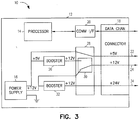
- One comparative embodiment of a manual jumper routing which is not describing the claimed invention is a configuration where the +12V output is either directly connected to the +12V input or it is generated via power booster circuitry 26 from the +5V output. This reduces demand on the +12V input and leaves more reserves on the +12V input. In one such embodiment, this extra reserve of the +12V input is boosted to +24V and supplies a +24V output (as shown in Fig. 3 ).
- connector 18 includes a third power conductor 34 connected to a booster 32.
- booster 32 boosts power from the +12V rail of power supply 16 to +24V.
- a booster connected to the +5V rail of power supply 16 provides the boost to +24V.
- the dual booster architecture of Fig. 3 has some advantages over the single booster architecture of Figs. 1 and 2 .
- USB+ devices will primarily use the +12V and +24V output as their power source.
- a single booster architecture can put the entire high power demand on the +12V power rail, quickly exhausting the reserve power.
- the dual booster approach distributes this power demand over multiple power rails.
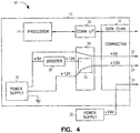
- +24V is supplied by an external power supply 36 routed through computer 10 to conductor 34.
- An example of this is shown in Fig. 4 .
- An optional external power booster supply can also be connected if the overall internal power reserve is not sufficient for the total power demand.
- the input of this booster supply is typically +24V, but it could be theoretically anything else.
- power router 28 of Fig. 1 monitors, either by itself or in cooperation with processor 14, the load on the +5V and +12V power rails. As power demand increases due to either additional internal or external demand, the corresponding power rail will experience a voltage drop. The power routing circuitry could then route reserve power from power rails having reserve to power rails experiencing heavy demand.
- power router 28 operates automatically to draw power from two or more sources.
- automatic routing circuitry includes power-monitoring circuitry. By actively monitoring the output voltage, power router 28 can detect overload of an individual power rail and route additional reserve power to the power rail under heavy demand.
- Fig. 5 One such embodiment is shown in Fig. 5 .
- internal power supply 16 provides a first and a second power rail (at +5V and +12V, respectively).
- Power routing and conversion unit 40 receives power from the first and second power rails and outputs power at a first, second and third nominal voltage.
- the nominal voltages are +5V, +12V and +24V, but any combination of voltages could be supplied in a similar manner.
- power routing and conversion unit 40 includes reserve power router 42, output power conditioner 44 and control logic 46.
- Control logic 46 monitors the first, second and third nominal voltages and adjusts the power drawn by reserve power router 42 from the first and second power rails accordingly, driving, for instance, the +12V power conductor with power selectively drawn from the +12V power rail and from the output of booster 26. In one such embodiment, control logic 46 also controls operation of output power conditioner 44.
- power routing and conversion unit 40 employs a dual booster architecture (such as is shown in Fig. 3 ). Such an embodiment is shown in Fig. 6 .
- the +24V output is boosted out of the +12V power rail and the +12V output is primarily generated from the +12V power rail as well.
- the +12V output is, however, monitored continuously by control logic 46 and, upon detecting a pre-set minimum threshold, the secondary +5V to +12V booster circuit transfers reserve power from the +5V into the +12V power rail.
- the primary power booster will transfer power from the +12V input to the +24V output. Additional devices connected either to the +12V or +24V will put more demand on the +12V output causing it to drop the voltage and reaching the minimum threshold. At that point the secondary +5V to +12V booster will transfer power into the +12V rail.
- power routing and conversion unit 40 employs a single booster with external power supply 36 such as is shown in Fig. 4 .
- power routing and conversion unit 40 uses the +24V power input of external power supply 36 to supplement the power available on the +12V or +5V outputs.
- power power routing and conversion unit 40 uses the +24V power input of external power supply 36 to supplement the power available on the +12V or +5V outputs.
- a PCI card could be used to add powered USB to a computer system.
- power routing and conversion unit 40 would be provided with a USB controller in a PCI card form factor in order to provide powered USB.
- Other serial and parallel communications interfaces could be provided in a similar manner.
- the PCI card includes a connector for connecting the card to an external power supply (such as external power supply 36 shown in Figs. 4 and 5 ).
- computer is defined to include any digital or analog data processing unit. Examples include any personal computer, workstation, set top box, mainframe, server, supercomputer, laptop or personal digital assistant capable of embodying the inventions described herein. Although specific embodiments have been illustrated and described herein, it will be appreciated by those of ordinary skill in the art that any arrangement that is calculated to achieve the same purpose may be substituted for the specific embodiment shown.
Landscapes
- Engineering & Computer Science (AREA)
- General Engineering & Computer Science (AREA)
- Theoretical Computer Science (AREA)
- Computer Hardware Design (AREA)
- Physics & Mathematics (AREA)
- General Physics & Mathematics (AREA)
- Power Sources (AREA)
Claims (13)
- Procédé de fourniture de puissance à des dispositifs externes qui sont connectés à un ordinateur (10) qui comporte un carter d'ordinateur (12), dans lequel le carter d'ordinateur (12) inclut un connecteur accessible de façon externe (18) qui comporte un premier conducteur de puissance (24) et un conducteur de mise à la masse, le procédé comprenant :l'installation d'une alimentation en puissance (16) dans le carter d'ordinateur (12), dans lequel l'alimentation en puissance (16) inclut une masse et des premier et deuxième rails de puissance, dans lequel le premier rail de puissance est à une première tension nominale et le deuxième rail de puissance est à une deuxième tension nominale ;la connexion électrique d'un premier moyen d'amplification (26) sur le premier rail de puissance, dans lequel le premier moyen d'amplification (26) inclut une sortie de premier moyen d'amplification et dans lequel la sortie de premier moyen d'amplification est à la deuxième tension nominale ;la connexion électrique du deuxième rail de puissance et de la sortie du premier moyen d'amplification (26) sur un moyen d'acheminement de puissance (28, 40) ; etle pilotage du premier conducteur de puissance (24) à l'aide de la puissance qui est tirée de façon sélective depuis le deuxième rail de puissance et depuis la sortie de premier moyen d'amplification, dans lequel le pilotage inclut la conversion dynamique de la puissance de réserve qui est disponible sur les premier et deuxième rails de puissance selon approximativement la deuxième tension nominale et l'émission en sortie de la puissance convertie de façon dynamique sur le dispositif externe.
- Procédé selon la revendication 1, dans lequel le procédé comprend en outre :la connexion électrique d'un second moyen d'amplification (32) sur le deuxième rail de puissance, dans lequel le second moyen d'amplification émet en sortie de la puissance à une troisième tension nominale ; etla connexion électrique d'une sortie du second moyen d'amplification (32) sur un second conducteur de puissance (34).
- Procédé selon l'une quelconque des revendications 1 et 2, dans lequel le procédé comprend en outre la connexion électrique des conducteurs de puissance et de mise à la masse sur le dispositif externe.
- Procédé selon l'une quelconque des revendications 1 et 2, dans lequel le pilotage du premier conducteur de puissance (24) inclut :la détection d'une tension sur le premier conducteur de puissance (24) ; etle fait de tirer de la puissance depuis le deuxième rail de puissance et depuis la sortie de premier moyen d'amplification en fonction de la tension qui est détectée sur le premier conducteur de puissance (24).
- Système pour fournir de la puissance à des dispositifs externes qui sont connectés à un ordinateur (10) qui comporte un carter d'ordinateur (12), un processeur (14) qui est installé dans le carter d'ordinateur (12) et une alimentation en puissance (16) qui est installée dans le carter d'ordinateur (12), dans lequel l'alimentation en puissance (16) est connectée au processeur (14) et dans lequel l'alimentation en puissance (16) inclut un rail de mise à la masse, un premier rail de puissance qui présente une première tension nominale et un deuxième rail de puissance qui présente une deuxième tension nominale, dans lequel le système comprend :un premier moyen d'amplification (26) destiné à être connecté électriquement sur le premier rail de puissance, dans lequel le premier moyen d'amplification (26) dispose de la capacité d'amplifier la puissance qui provient du premier rail de puissance jusqu'à une tension qui est approximativement égale à la deuxième tension nominale ;un moyen d'acheminement de puissance (28, 40) destiné à être connecté électriquement sur le premier moyen d'amplification et sur le deuxième rail de puissance ; etun connecteur accessible de façon externe (18), dans lequel le connecteur (18) inclut un conducteur de mise à la masse et des premier et second conducteurs de puissance (22, 24), le premier conducteur de puissance (22) étant destiné à être connecté électriquement sur le premier rail de puissance et le second conducteur de puissance (24) étant destiné à être connecté électriquement sur le moyen d'acheminement de puissance (28, 40) ; dans lequel :
le moyen d'acheminement de puissance (28, 40), lorsqu'il est connecté électriquement, pilote le second conducteur de puissance (24) à approximativement la deuxième tension nominale à l'aide de la puissance qui est tirée de façon sélective depuis le premier moyen d'amplification (26) et le deuxième rail de puissance, dans lequel le moyen d'acheminement de puissance (28, 40), lorsqu'il est connecté électriquement, convertit de façon dynamique la puissance de réserve qui est disponible sur les premier et deuxième rails de puissance selon approximativement la deuxième tension nominale et émet en sortie la puissance convertie de façon dynamique sur le dispositif externe. - Système selon la revendication 5, dans lequel le système comprend l'ordinateur (10).
- Système selon la revendication 5, dans lequel l'ordinateur (10) comprend en outre une interface de communication (20), qui est connectée au processeur (14), pour communiquer avec le dispositif externe, dans lequel le connecteur accessible de façon externe (18) est configuré de sorte qu'il est connecté électriquement sur l'interface de communication (20).
- Système selon la revendication 7, dans lequel l'interface de communication (20) inclut une interface de communication série.
- Système selon la revendication 7, dans lequel l'interface de communication (20) inclut une interface de bus série universel (USB).
- Système selon la revendication 7, dans lequel l'interface de communication (20) inclut une interface de communication parallèle.
- Système selon la revendication 5, dans lequel le système comprend un kit d'équipement complémentaire qui convient pour ajouter un connecteur alimenté en puissance sur l'ordinateur (10).
- Système selon l'une quelconque des revendications 5 à 11, dans lequel le système comprend en outre un second moyen d'amplification (32), dans lequel le second moyen d'amplification (32) peut être connecté électriquement sur le premier rail de puissance et sur un troisième rail de puissance et dans lequel le second moyen d'amplification (32) dispose de la capacité d'amplifier la puissance qui provient du premier rail de puissance jusqu'à une troisième tension nominale et d'émettre en sortie la troisième tension nominale sur le troisième rail de puissance.
- Système selon l'une quelconque des revendications 5 à 11, dans lequel le système comprend en outre un second moyen d'amplification (32), dans lequel le second moyen d'amplification (32) peut être connecté électriquement sur le deuxième rail de puissance et sur un troisième rail de puissance et dans lequel le second moyen d'amplification (32) dispose de la capacité d'amplifier la puissance qui provient du deuxième rail de puissance jusqu'à une troisième tension nominale et d'émettre en sortie la troisième tension nominale sur le troisième rail de puissance.
Applications Claiming Priority (2)
| Application Number | Priority Date | Filing Date | Title |
|---|---|---|---|
| US10/865,018 US7240229B2 (en) | 2004-06-10 | 2004-06-10 | System and method for routing data and power to external devices |
| PCT/US2005/020373 WO2005124515A2 (fr) | 2004-06-10 | 2005-06-09 | Systeme et procede d'acheminement de donnees et d'energie vers des dispositifs externes |
Publications (2)
| Publication Number | Publication Date |
|---|---|
| EP1766497A2 EP1766497A2 (fr) | 2007-03-28 |
| EP1766497B1 true EP1766497B1 (fr) | 2018-05-30 |
Family
ID=34972509
Family Applications (1)
| Application Number | Title | Priority Date | Filing Date |
|---|---|---|---|
| EP05760528.9A Expired - Lifetime EP1766497B1 (fr) | 2004-06-10 | 2005-06-09 | Systeme et procede d'acheminement de donnees et d'energie vers des dispositifs externes |
Country Status (3)
| Country | Link |
|---|---|
| US (1) | US7240229B2 (fr) |
| EP (1) | EP1766497B1 (fr) |
| WO (1) | WO2005124515A2 (fr) |
Families Citing this family (10)
| Publication number | Priority date | Publication date | Assignee | Title |
|---|---|---|---|---|
| US7240229B2 (en) | 2004-06-10 | 2007-07-03 | Digi International Inc. | System and method for routing data and power to external devices |
| TWI338840B (en) * | 2006-11-01 | 2011-03-11 | Wistron Corp | Expandable express card and its method for isolating noise and method for combining functionalities of the express card with a non-host device |
| US7701080B2 (en) * | 2007-02-13 | 2010-04-20 | Ford Global Technologies, Llc | USB for vehicle application |
| US20090307390A1 (en) * | 2008-06-04 | 2009-12-10 | Broadcom Corporation | Access of built-in peripheral components by internal and external bus pathways |
| US8661268B2 (en) * | 2010-02-22 | 2014-02-25 | Apple Inc. | Methods and apparatus for intelligently providing power to a device |
| KR20120043851A (ko) * | 2010-10-27 | 2012-05-07 | 삼성전자주식회사 | 컨버터 및 이와 연결되는 화상형성장치 |
| CN103176579A (zh) * | 2011-12-22 | 2013-06-26 | 刘骅毅 | 一种计算机电源 |
| GB2520857B (en) | 2012-09-20 | 2019-12-04 | Hewlett Packard Development Co | Detecting key positions to determine a type of cable |
| CN104021809A (zh) * | 2013-03-01 | 2014-09-03 | 鸿富锦精密电子(天津)有限公司 | Usb存储器 |
| US11402888B1 (en) * | 2021-02-04 | 2022-08-02 | Cisco Technology, Inc. | USB type-A power extension to support high power modules |
Family Cites Families (10)
| Publication number | Priority date | Publication date | Assignee | Title |
|---|---|---|---|---|
| US5483656A (en) * | 1993-01-14 | 1996-01-09 | Apple Computer, Inc. | System for managing power consumption of devices coupled to a common bus |
| KR960030631A (ko) * | 1995-01-27 | 1996-08-17 | 김광호 | 절전형 팩시밀리 |
| DE29511762U1 (de) | 1995-07-21 | 1995-09-21 | Price, Robert, 35578 Wetzlar | Gleichstromversorgungs-Adapter für Personal Computer |
| KR100190599B1 (ko) | 1996-04-22 | 1999-06-01 | 윤종용 | 내부 전원을 사용할 수 있는 브라켓 |
| US6357011B2 (en) * | 1998-07-15 | 2002-03-12 | Gateway, Inc. | Bus-powered computer peripheral with supplement battery power to overcome bus-power limit |
| US6697892B1 (en) | 1999-07-08 | 2004-02-24 | Intel Corporation | Port expansion system |
| WO2002086751A1 (fr) | 2001-04-24 | 2002-10-31 | Broadcom Corporation | Systeme et procede de chargement et gestion de memoire au format asf |
| US20030110403A1 (en) | 2001-12-10 | 2003-06-12 | Intel Corporation | System for shared power supply in computer peripheral devices |
| US7642672B2 (en) * | 2004-04-05 | 2010-01-05 | Agere Systems Inc. | Control of integrated supply voltage regulation due to on-chip internal resistance fluctuations in integrated circuits |
| US7240229B2 (en) | 2004-06-10 | 2007-07-03 | Digi International Inc. | System and method for routing data and power to external devices |
-
2004
- 2004-06-10 US US10/865,018 patent/US7240229B2/en not_active Expired - Lifetime
-
2005
- 2005-06-09 EP EP05760528.9A patent/EP1766497B1/fr not_active Expired - Lifetime
- 2005-06-09 WO PCT/US2005/020373 patent/WO2005124515A2/fr not_active Ceased
Non-Patent Citations (1)
| Title |
|---|
| None * |
Also Published As
| Publication number | Publication date |
|---|---|
| US7240229B2 (en) | 2007-07-03 |
| WO2005124515A3 (fr) | 2006-05-04 |
| WO2005124515A2 (fr) | 2005-12-29 |
| EP1766497A2 (fr) | 2007-03-28 |
| US20050278554A1 (en) | 2005-12-15 |
Similar Documents
| Publication | Publication Date | Title |
|---|---|---|
| EP1576710B1 (fr) | Procede et systeme de commande et de surveillance d'un reseau de regulateurs de point de charge | |
| US8261102B2 (en) | Power management system capable of saving power and optimizing operating efficiency of power supplies for providing power with back-up or redundancy to plural loads | |
| US10521001B2 (en) | System and method for rack mountable modular DC power unit | |
| US8782449B2 (en) | Power supply system with a plurality of power supply units capable of powering a plurality of load units depending on the type and operation state of each load unit | |
| US7664974B2 (en) | Storage control device and control method therefor | |
| EP1277121B1 (fr) | Système fournissant des possibilités d'expansion externes à un ordinateur personel | |
| EP2330710A2 (fr) | Ensemble électronique équipé d'un circuit parallèle pour connecter électriquement deux unités de batterie | |
| US20070114852A1 (en) | Parallel uninterruptible power supply system | |
| US20040003306A1 (en) | Information processing apparatus and power supply method used in the apparatus | |
| US20060277420A1 (en) | Power supply for portable computer | |
| EP1766497B1 (fr) | Systeme et procede d'acheminement de donnees et d'energie vers des dispositifs externes | |
| CN100576655C (zh) | 能够为计算机与外设单元供电的含外设单元的电力适配器 | |
| US7851944B2 (en) | Integrated uninterrupted power supply unit | |
| US7592715B2 (en) | Multiple sources of operating power to a load | |
| CN112701936A (zh) | 计算机电源供应组件及其制造方法 | |
| TW201416865A (zh) | 外接式儲存裝置及其驅動方法 | |
| US20050162017A1 (en) | Power supply device for peripheral device | |
| KR100541728B1 (ko) | 컴퓨터시스템 | |
| US20140125128A1 (en) | Power redundancy apparatus for rack-mounted server | |
| JP2000010671A (ja) | 周辺機器接続装置を使用した電力供給装置 | |
| US7190267B2 (en) | System and method for managing power control and data communication among devices | |
| CN106557141A (zh) | 一种电子设备 | |
| CN210297531U (zh) | 电源供应单元 | |
| KR20080097847A (ko) | 전원 분배기 및 이를 이용한 전자 장치 | |
| US20210181776A1 (en) | Interface arrangement, computer system and method |
Legal Events
| Date | Code | Title | Description |
|---|---|---|---|
| PUAI | Public reference made under article 153(3) epc to a published international application that has entered the european phase |
Free format text: ORIGINAL CODE: 0009012 |
|
| 17P | Request for examination filed |
Effective date: 20070110 |
|
| AK | Designated contracting states |
Kind code of ref document: A2 Designated state(s): DE FR GB |
|
| DAX | Request for extension of the european patent (deleted) | ||
| RBV | Designated contracting states (corrected) |
Designated state(s): DE FR GB |
|
| 17Q | First examination report despatched |
Effective date: 20170105 |
|
| GRAP | Despatch of communication of intention to grant a patent |
Free format text: ORIGINAL CODE: EPIDOSNIGR1 |
|
| INTG | Intention to grant announced |
Effective date: 20171215 |
|
| GRAS | Grant fee paid |
Free format text: ORIGINAL CODE: EPIDOSNIGR3 |
|
| GRAA | (expected) grant |
Free format text: ORIGINAL CODE: 0009210 |
|
| AK | Designated contracting states |
Kind code of ref document: B1 Designated state(s): DE FR GB |
|
| REG | Reference to a national code |
Ref country code: GB Ref legal event code: FG4D |
|
| REG | Reference to a national code |
Ref country code: FR Ref legal event code: PLFP Year of fee payment: 14 |
|
| REG | Reference to a national code |
Ref country code: DE Ref legal event code: R096 Ref document number: 602005054049 Country of ref document: DE |
|
| REG | Reference to a national code |
Ref country code: DE Ref legal event code: R097 Ref document number: 602005054049 Country of ref document: DE |
|
| PLBE | No opposition filed within time limit |
Free format text: ORIGINAL CODE: 0009261 |
|
| STAA | Information on the status of an ep patent application or granted ep patent |
Free format text: STATUS: NO OPPOSITION FILED WITHIN TIME LIMIT |
|
| 26N | No opposition filed |
Effective date: 20190301 |
|
| PGFP | Annual fee paid to national office [announced via postgrant information from national office to epo] |
Ref country code: GB Payment date: 20240425 Year of fee payment: 20 |
|
| PGFP | Annual fee paid to national office [announced via postgrant information from national office to epo] |
Ref country code: DE Payment date: 20240423 Year of fee payment: 20 |
|
| PGFP | Annual fee paid to national office [announced via postgrant information from national office to epo] |
Ref country code: FR Payment date: 20240422 Year of fee payment: 20 |
|
| REG | Reference to a national code |
Ref country code: DE Ref legal event code: R071 Ref document number: 602005054049 Country of ref document: DE |
|
| REG | Reference to a national code |
Ref country code: GB Ref legal event code: PE20 Expiry date: 20250608 |
|
| PG25 | Lapsed in a contracting state [announced via postgrant information from national office to epo] |
Ref country code: GB Free format text: LAPSE BECAUSE OF EXPIRATION OF PROTECTION Effective date: 20250608 |