EP1770008A2 - Multiple steer by wire helm system - Google Patents
Multiple steer by wire helm system Download PDFInfo
- Publication number
- EP1770008A2 EP1770008A2 EP06121031A EP06121031A EP1770008A2 EP 1770008 A2 EP1770008 A2 EP 1770008A2 EP 06121031 A EP06121031 A EP 06121031A EP 06121031 A EP06121031 A EP 06121031A EP 1770008 A2 EP1770008 A2 EP 1770008A2
- Authority
- EP
- European Patent Office
- Prior art keywords
- steering
- helm
- signals
- apparatuses
- rudder
- Prior art date
- Legal status (The legal status is an assumption and is not a legal conclusion. Google has not performed a legal analysis and makes no representation as to the accuracy of the status listed.)
- Granted
Links
Images



Classifications
-
- B—PERFORMING OPERATIONS; TRANSPORTING
- B63—SHIPS OR OTHER WATERBORNE VESSELS; RELATED EQUIPMENT
- B63H—MARINE PROPULSION OR STEERING
- B63H25/00—Steering; Slowing-down otherwise than by use of propulsive elements; Dynamic anchoring, i.e. positioning vessels by means of main or auxiliary propulsive elements
- B63H25/02—Initiating means for steering, for slowing down, otherwise than by use of propulsive elements, or for dynamic anchoring
Definitions
- This invention relates to helm steering systems and, in particular, to multiple helm steer-by-wire steering systems for marine craft or other vehicles.
- Conventional marine steering systems couple one or more helms to one or more rudders utilizing mechanical or hydraulic means.
- cables conventionally have been used to operatively connect a helm to the rudder.
- the helm has been provided with a manual hydraulic pump operated by rotation of the steering wheel.
- Hydraulic lines connect the helm pump to a hydraulic actuator connected to the rudder.
- Some marine steering systems provide a power assist via an engine driven hydraulic pump, similar to the hydraulic power steering systems found in automobiles. In those systems a cable helm or a hydraulic helm mechanically controls the valve of a hydraulic assist cylinder.
- steer-by-wire steering systems potentially offer significant advantages for marine applications. Such systems may yield reduced costs, potentially more reliable operation, more responsive steering, greater tailored steering comfort, and simplified installation. Smart helms allow an original equipment manufacturer (OEM) to tailor steering feel and response to craft type and operator demographics. Steer-by-wire steering systems are also better adapted for modern marine craft fitted with CAN buses or similar communications buses and may make use of electrical information from speed, load and navigation, autopilot or anti-theft devices for example.
- OEM original equipment manufacturer
- a steering apparatus for a marine craft.
- the steering apparatus comprises two or more helm apparatuses.
- Each of the helm apparatuses has a steering device.
- the helm apparatuses provide helm signals indicative of the incremental and decremental movement of the respective steering device.
- the helm apparatuses are used to steer a steering element which is connected to a steering element actuator.
- the steering element actuator moves the steering element under control from a steering control means.
- the steering control means is responsive to the helm signals of each of the helm apparatuses and provides steering signals to the steering element actuator to steer the steering element in accordance with movement of the steering devices of the helm apparatuses.
- a steering apparatus for a marine craft.
- the steering apparatus comprises two or more helm apparatuses.
- Each of the helm apparatuses has a steering device.
- the helm apparatuses provide helm signals indicative of the incremental and decremental movement of the respective steering device.
- the helm apparatuses are used to steer a steering element which is connected to a steering element actuator.
- the steering element actuator moves the steering element under control from a steering control means.
- the steering control means is responsive to the helm signals of each of the helm apparatuses and provides steering signals to the steering element actuator to steer the steering element in accordance with movement of the steering devices of the helm apparatuses.
- the steering signals are derived from aggregating the helm signals of each of the helm apparatuses.
- a steering apparatus for a marine craft.
- the steering apparatus comprises two or more helm apparatuses.
- Each of the helm apparatuses has a steering device.
- the helm apparatuses provide helm signals indicative of the incremental and decremental movement of the respective steering device.
- the helm apparatuses are used to steer a steering element which is connected to a steering element actuator.
- the steering element actuator moves the steering element under control from a steering control means.
- the steering control means is responsive to the helm signals of each of the helm apparatuses and provides steering signals to the steering element actuator to steer the steering element in accordance with movement of the steering devices of the helm apparatuses.
- the steering signals are derived from the helm signals from one of the helm apparatuses which is steered fastest when a plurality of the helm apparatuses are simultaneously steered.
- a method of steering a marine craft that has a plurality of helms and a steering element, and each of the helms has a steering device.
- the method comprises the steps of generating helm signals from the steering devices.
- the helm signals are indicative of the incremental and decremental movement of the steering devices.
- Steering signals are generated that are derived from the helm signals.
- the steering element is actuated with the steering signals to effect steering of the marine craft.
- the present invention has the advantage of simplifying helm design. All helms in a vessel can be physically identical. That is, no master helm is necessary, nor is a special master setup routine required to configure the master helm. This simplifies manufacturing and the ordering process for the helm manufacturer and marine craft builders.
- Taking control of the marine craft is advantageously intuitive and quick with the present invention.
- the user can grab the wheel of any helm and start steering, without having to login or go through a transfer control routine as with prior art multiple helm systems. This improves the safety and convenience of operating the marine craft or vessel.
- the aspect of the present invention wherein the fastest steered helm controls the steering of the marine craft over other helms has many advantages.
- the faster win scenario signifies that emergency movement is most likely with a higher rate of turn of the steering wheel. Additionally, adults tend to turn boats faster than children.
- the faster win scenario also advantageously ignores minor, unintentional movement from inactive helms, typically due to vibration or wind.
- a conventional marine steering system having multiple helms includes a hydraulic cylinder 10, a first hydraulic helm and a second hydraulic helm indicated generally by reference characters 12 and 14 respectively.
- the hydraulic cylinder 10 operates to actuate a rudder to steer the marine vessel.
- the fist hydraulic helm 12 is connected in parallel to the second hydraulic helm 14.
- a hydraulic cylinder flow 20 equals the sum of the flow 16 and the flow 18.
- the flow 16 is then greater than the flow 18 and dominates the flow 20 of the hydraulic cylinder 10.
- a communication bus 22 which in this example is a Local Interconnect Network (LIN) bus.
- the communication bus 22 can be other types of communication buses, either wired or wireless, such as CAN, I 2 C, SPI, USB, RS232, Ethernet, wireless Ethernet, Bluetooth and Zigabee.
- the communication bus 22 is used as a communication backbone for other elements in the multiple helm steer-by-wire steering system as will be shown below.
- steer-by-wire helms are connected to the communication bus 22. In other embodiments any other number of steer-by-wire helms can be connected to the communication bus.
- the steer-by-wire helms 24 and 26 include steering wheels 28 and 30 respectively in this example, and helm controllers 29 and 31 respectively. As understood by one skilled in the art, other types of steering devices can be used in other examples.
- a steering element in this example a rudder 32, is connected to a rudder actuator 34.
- the rudder could be replaced by other steering means such as an inboard/outboard drive or an outboard motor.
- the rudder 32 operates to change the direction of the marine vessel and the rudder actuator 34 changes the orientation of the rudder with respect to the marine vessel.
- the rudder actuator 34 is connected to a rudder actuator controller 36 for controlling the rudder actuator.
- the rudder actuator 34 comprises a sensor 33 that provides positional information about the rudder actuator.
- the rudder actuator controller 36 is connected to the communication bus 22.
- each of the helm controllers 29 and 31 includes an encoder 50, a helm processor 52 and a bus transceiver 54.
- the encoder is connected to the helm processor 52 by connection 56.
- the helm processor 52 is connected to the bus transceiver by connection 58.
- the connections 56 and 58 are electrical connections, but other types of connections are possible, such as wireless connections, and these are intended to be within the scope of the present invention.
- Each of the encoders 50 is responsive to its respective steering wheel 28 and 30 and, in this example, provides helm signals in the form of quadrature signals to the helm processor over connection 56.
- the helm signals are representative of the increment or decrement in the movement of steering wheels 28 and 30. It is to be understood that the helm signals are logical signals herein and can appear in different forms in different parts of the multiple steer by wire helm system, for example a digital electrical signal or a digital wireless signal.
- the helm processor 52 is a microcontroller in this example and comprises a data processing means and a data storage means.
- the helm processor 52 stores and executes software instructions of a control program.
- the helm processor can comprise a microprocessor and a memory.
- the memory can comprise a non-volatile memory, such as a Read Only Memory (ROM) or an Electrically Eraseable Programmable ROM (E 2 PROM), and a volatile memory such as a Random Access Memory (RAM) or other types of memory.
- ROM Read Only Memory
- E 2 PROM Electrically Eraseable Programmable ROM
- RAM Random Access Memory
- helm controllers 29 and 30 can include a programmable logic device or an ASIC instead of the helm processor 52.
- the control program of the helm processor 52 includes instructions to receive the helm signals, in the form of quadrature signals in this example, from the encoder 50 and instructions to transmit the helm signals onto the communication bus 22.
- the bus transceiver 54 electrically conditions any signal from the helm processor 52 for transmission onto the communication bus 22.
- the bus transceiver also conditions signals from the communication bus for reception in the helm processor 52.
- the rudder actuator controller 36 includes a bus transceiver 70, a rudder processor 72 and a motor driver 74 for the rudder actuator 34.
- the bus transceiver is connected to the rudder processor by connection 76.
- the rudder processor is connected to the motor driver 74 by connection 78 and to the rudder actuator 34 by connection 80.
- the motor driver is connected to the rudder actuator 34 by connection 82.
- the connections 76, 78, 80 and 82 are electrical connections, but other types of connections are possible.
- the motor driver 74 drives the rudder 32 and the sensor 33 provides positional feedback information of the rudder 32 over the connection 80.
- bus transceiver 70 The operation of the bus transceiver 70 is similar in principle to the operation of bus transceiver 54 above.
- the bus transceiver electrically conditions signals from the communication bus 22 and from the rudder processor 72.
- the helm processor 72 is a microcontroller in this example and comprises a data processing means and a data storage means.
- the helm processor 72 stores and executes software instructions of a control program.
- the helm processor can comprise a microprocessor and a memory.
- the memory can comprise a non-volatile memory, such as a Read Only Memory (ROM) or an Electrically Eraseable Programmable ROM (E 2 PROM), and a volatile memory such as a Random Access Memory (RAM) or other types of memory.
- ROM Read Only Memory
- E 2 PROM Electrically Eraseable Programmable ROM
- RAM Random Access Memory
- rudder actuator controller 36 can include a programmable logic device or an ASIC instead of the helm processor 72.
- the control program of the rudder processor 72 includes instructions to receive signals from the communication bus 22 via bus transceiver 70 and instructions to generate rudder signals in the form of motor driver signals indicated generally by reference numeral 84.
- the rudder signals are logical signals and are used to actuate the rudder actuator 34.
- the motor driver 74 electrically conditions the rudder signals in the form of motor driver signals 84 from the rudder processor 72 into rudder signals for the rudder actuator 34, as indicated by reference numeral 42 in FIGS. 2 and 4. It is to be understood that the rudder signals are logical signals herein and can appear in different forms in different parts of the multiple steer by wire helm system.
- the rudder 32 has a default position in which it allows the marine vessel to continue in its current direction.
- the steering wheels 28 and 30 have default positions corresponding to the default position of the rudder 32.
- a clockwise or counterclockwise movement of either of the steering wheels 28 and 30 away from their default positions is considered a steering increment, whereas a movement towards their default positions is considered a steering decrement.
- the steer-by-wire helms 24 and 26 do not require information on the absolute position of the rudder 32.
- the helms 24 and 26 merely provide incremental indications of movement of the steering wheels 28 and 30, and respond to steering resistance signals from the controller 36 in order to provide rotational resistance to the steering wheels to effect steering feedback resistance.
- the steering resistance signals from the controller 36 are related to the position of the rudder 32.
- the sensor 33 provides positional information of the rudder 32 to the rudder actuator controller 36.
- the rudder actuator controller 36 sends the steering resistance signals to the helms 24 and 26 over the communication bus 22 for controlling the steering feedback resistance applied to the steering wheels 28 and 30 respectively.
- the steering feedback resistance is experienced by a person manipulating the steering wheel as resistance in turning the wheel, in a certain direction.
- the steering feedback resistance applied to the steering wheel is experienced by the person as increased resistance in the direction of steering.
- the steering feedback resistance applied to the steering wheel prevents the person from steering the wheel further in that direction of steering.
- the helm controller 29 also has a brake in the form of a stop mechanism 94, a drive shaft 96 and stop electronics 98, the helm controller 31 having corresponding elements.
- the stop mechanism 94 is similar to the stop mechanism described in United States Patent Application No. 10/926,327 , which is incorporated herein by reference, and includes in this example a multi-plate clutch having a plurality of clutch plates, and an actuator in the form of a solenoid with an armature.
- the armature is provided with a shaft which is press fitted to connect the armature to the inside of a drum of the drive shaft 94. Accordingly, the armature is rigidly connected to the drive shaft 94.
- the helm processor 52 When the rudder 32 reaches the maximum steered position, i.e. a starboard or port hard-over position, the helm processor 52 receives steering resistance signals from the communication bus 22 and accordingly applies a stop signal to the stop mechanism 94 through the stop electronics 98. The stop signal actuates the solenoid to force the plates together causing friction between the plates thereby stopping rotation of the drive shaft 96. There is some play between the steering device 28 and the drive shaft 96, and since the encoder 50 detects movement of the steering device 28, the helm processor 52 can detect movement of the steering device away from the maximum steered position so that it can release the stop mechanism enabling the drive shaft to rotate away from the maximum steered position as well thereby providing steering decrement signals.
- Another aspect of the present invention is instantaneous synchronization of steering wheels 28 and 30.
- the steering wheel 28 is one quarter turn, i.e. 90 degrees, from end stop, and a person turns it one eighth of a full rotation towards end stop, then the wheel has one eighth of a turn remaining before reaching an end stop.
- the end stop occurs when the steering feedback resistance applied to the wheel prevents the wheel from turning in a certain direction, and which corresponds to a maximum steered position of the rudder 32.
- wheel 30 can turn at most one eighth of a turn before reaching the end stop. This is possible since the rudder actuator controller 36 is aware of the absolute rudder position due to the sensor 33, and therefore the controller 36 can inform the helms 24 and 26 accordingly.
- the steer-by-wire helms 24 and 26 and the rudder actuator controller 36 can operate in an accumulated steering manner.
- a first operator steers the steering wheel 28 which causes the steer-by-wire helm 24 to generate a helm signal 38 representative of the increment or decrement in the steering wheel.
- the helm signal 38 is directed onto the communication bus 22. Whenever the first operator changes the position of the steering wheel 28 the helm signal 38 is generated and is directed onto the communication bus 22.
- helm signal 40 which is correspondingly directed onto the communication bus 22.
- the helm signals 38 and 40 are signed signals representative of an increment in steering, in which case they are positive in this example, or a decrement in steering, in which case they are negative in this example.
- the helm signals 38 and 40 are received by the rudder actuator controller 36 whenever they are directed onto the communication bus 22.
- the control program of the rudder processor 72 includes instructions to provide an aggregate signal equal to the accumulation of the helm signals 38 and 40.
- the rudder actuator controller 36 continuously receives the helm signals 38 and 40 and continuously updates the aggregate signal with the helm signal values.
- the control program of the rudder processor 72 periodically generates a rudder signal 42, which is equivalent to the sum of the aggregate helm signal and a previous rudder signal.
- the rudder signal 42 is applied to the rudder actuator 34 to actuate the rudder 32.
- the aggregate signal is reset to a zero value and the previous rudder signal is equated to the rudder signal.
- This embodiment simulates the operation of the conventional multiple helm hydraulic marine steering system using steer-by-wire helms 24 and 26. If the first operator steers more frequently than the second operator then there will be more helm signals 38 from the steer-by-wire helm 24 than helm signals 40 from the steer-by-wire helm 26. Accordingly, the aggregate signal will be dominated by the helm signal 38, and so will the rudder signal 42. If the first operator steers faster than the second operator then the helm signals 38 from the steer-by-wire helm 24 will be greater in absolute value than the absolute value of helm signals 40 from the steer-by-wire helm 26. Accordingly, the aggregate signal, again, will be dominated by the helm signal 38, and so will the rudder signal 42.
- the communication bus 22 makes it easier to add additional helms in the marine steering system.
- the rudder signal 42 may direct the rudder actuator 34 to steer too quickly. This concern may be solved by limiting the maximum rate of steering by the control program in the rudder actuator controller 36 or, alternatively, by the size of the rudder actuator 34.
- This accumulating steering arrangement has the advantage of simplifying helm design. All helms can be physically identical. That is, no master helm is necessary, nor is a special master setup routine to configure the master helm. This simplifies manufacturing and the ordering process for the helm manufacturer and marine vessel builders.
- Taking control of the marine vessel is advantageously intuitive and quick in this embodiment.
- the user can grab the wheel of either helm and start steering, without having to log in or go through a transfer control routine as with prior art multiple helm systems. This improves the safety of operating the marine vessel.
- a variation of the accumulating steering is a "faster win” scenario.
- the control program of the rudder processor 72 uses the helm signal with the largest amplitude, the other helm signals being discarded. In this situation, the user who steers the wheel the fastest has control of the boat.
- ⁇ new ⁇ previous + max ⁇ ⁇ ⁇ ⁇ 38 + ⁇ ⁇ ⁇ 40
- ⁇ new is the rudder signal
- ⁇ previous is the previous rudder signal
- ⁇ 38 is the helm signal 38
- ⁇ 40 is the helm signal 40
- max( ⁇ 38 + ⁇ 40 ) is the fastest helm signal.
- the faster win scenario signifies that emergency movement is most likely with a higher rate of turn of the steering wheel. Additionally, adults tend to turn boats faster than children. The faster win scenario also advantageously ignores minor, unintentional movement from inactive helms, typically due to vibration or wind.
- An optional collision acknowledgement indication can be used with either the accumulating steering or faster win steering scenarios, warning users that multiple helms are attempting to steer the boat. This promotes a dialog among the helmsman to coordinate steering control of the boat.
- FIG. 5 another embodiment of the present invention, wherein like parts to the previous embodiment have like reference numerals with an additional suffix ".2", includes helm apparatuses indicated generally by reference numeral 24.2 and 26.2. In other examples there can be any number of helm apparatuses. There is also a rudder 32.2, a rudder actuator 34.2 and a rudder actuator controller 36.2 for controlling the rudder actuator. As in the previous embodiment the apparatus may be used with other types of steering elements besides rudders.
- the helm apparatus 24.2 is directly connected to the rudder actuator controller 36.2 by electrical connection 90.
- the helm apparatus 24.2 includes a steering device 28.2 and a helm controller 29.2.
- the helm apparatus 26.2 is directly connected to the rudder actuator controller 36.2 by electrical connection 92.
- the helm apparatus 26.2 includes a steering device 30.2 and a helm controller 31.2.
- each of the helm controllers 29.2 and 31.2 includes an encoder 50.2. Each encoder 50.2 is connected directly to the rudder actuator controller 36.2. Each encoder 50.2 is responsive to one of the steering devices 28.2 and 30.2 and provides helm signals in the form of quadrature signals.
- the rudder actuator controller 36.2 includes a rudder processor 72.2 and a motor driver 74.2 for the rudder actuator 34.2.
- the rudder processor 72.2 is a microcontroller, in this example, and comprises a data processing means and a data storage means.
- the rudder processor 72.2 is connected to electrical connections 90 and 92.
- the helm processor 72.2 stores and executes software instructions of a control program.
- the helm processor 72.2 can comprise a microprocessor and a memory.
- the memory can comprise a non-volatile memory, such as a Read Only Memory (ROM) or an Electrically Eraseable Programmable ROM (E 2 PROM), and a volatile memory such as a Random Access Memory (RAM).
- ROM Read Only Memory
- E 2 PROM Electrically Eraseable Programmable ROM
- RAM Random Access Memory
- rudder actuator controller 36.2 can include a programmable logic device or an ASIC instead of the rudder processor 72.2.
- the control program of the rudder processor 72.2 includes instructions to receive the helm signals, in the form of quadrature signals in this example, from connections 90 and 92 and instructions to generate rudder signals in the form of motor driver signals indicated generally by reference numeral 84.2.
- the motor driver 74.2 electrically conditions the motor driver signals 84.2 from the rudder processor 72.2 into rudder signals 42.2 for the rudder actuator 34.2.
- This embodiment operates in a similar manner to the previous embodiments, i.e. with aggregate steering or faster win steering, therefore the operation will not be explained again.
- This embodiment has the advantage of being more cost effective since the connections 90 and 92 are less complex than the communication bus 22 of the previous embodiment.
- the previous embodiment has the advantage of being more robust, less coupled and more functionality, i.e. control signals can go between the helms and the rudder actuator controller 36, and between the rudder actuator controller and each of the helms.
Landscapes
- Chemical & Material Sciences (AREA)
- Engineering & Computer Science (AREA)
- Combustion & Propulsion (AREA)
- Mechanical Engineering (AREA)
- Ocean & Marine Engineering (AREA)
- Steering Control In Accordance With Driving Conditions (AREA)
- Toys (AREA)
- Control Of Position, Course, Altitude, Or Attitude Of Moving Bodies (AREA)
Abstract
Description
- This invention relates to helm steering systems and, in particular, to multiple helm steer-by-wire steering systems for marine craft or other vehicles.
- Conventional marine steering systems couple one or more helms to one or more rudders utilizing mechanical or hydraulic means. In smaller marine craft, cables conventionally have been used to operatively connect a helm to the rudder. Alternatively the helm has been provided with a manual hydraulic pump operated by rotation of the steering wheel. Hydraulic lines connect the helm pump to a hydraulic actuator connected to the rudder. Some marine steering systems provide a power assist via an engine driven hydraulic pump, similar to the hydraulic power steering systems found in automobiles. In those systems a cable helm or a hydraulic helm mechanically controls the valve of a hydraulic assist cylinder.
- It has been recognized that so-called steer-by-wire steering systems potentially offer significant advantages for marine applications. Such systems may yield reduced costs, potentially more reliable operation, more responsive steering, greater tailored steering comfort, and simplified installation. Smart helms allow an original equipment manufacturer (OEM) to tailor steering feel and response to craft type and operator demographics. Steer-by-wire steering systems are also better adapted for modern marine craft fitted with CAN buses or similar communications buses and may make use of electrical information from speed, load and navigation, autopilot or anti-theft devices for example.
- Various attempts have been made to provide a commercially viable steer-by-wire steering system for marine craft. An example is found in
United States Patent No. 6,273,771 to Buckley et al. which utilizes a CAN bus for a plurality of helms. Another is found inUnited States Patent No. 5,107,424 to Bird et al. A further example is found inUnited States Patent No. 6,311,634 to Ford et al. - However these earlier systems have not been completely successful in replacing more conventional hydraulic steering systems in multiple helm marine craft for example. Accordingly there is a need for an improved steer-by-wire steering system particularly adapted for multiple helm marine craft and also potentially useful for other steering applications such as tractors, forklifts and automobiles.
- According to a first aspect of the invention, there is provided a steering apparatus for a marine craft. The steering apparatus comprises two or more helm apparatuses. Each of the helm apparatuses has a steering device. The helm apparatuses provide helm signals indicative of the incremental and decremental movement of the respective steering device. The helm apparatuses are used to steer a steering element which is connected to a steering element actuator. The steering element actuator moves the steering element under control from a steering control means. The steering control means is responsive to the helm signals of each of the helm apparatuses and provides steering signals to the steering element actuator to steer the steering element in accordance with movement of the steering devices of the helm apparatuses.
- According to a second aspect of the invention, there is provided a steering apparatus for a marine craft. The steering apparatus comprises two or more helm apparatuses. Each of the helm apparatuses has a steering device. The helm apparatuses provide helm signals indicative of the incremental and decremental movement of the respective steering device. The helm apparatuses are used to steer a steering element which is connected to a steering element actuator. The steering element actuator moves the steering element under control from a steering control means. The steering control means is responsive to the helm signals of each of the helm apparatuses and provides steering signals to the steering element actuator to steer the steering element in accordance with movement of the steering devices of the helm apparatuses. The steering signals are derived from aggregating the helm signals of each of the helm apparatuses.
- According to a third aspect of the invention, there is provided a steering apparatus for a marine craft. The steering apparatus comprises two or more helm apparatuses. Each of the helm apparatuses has a steering device. The helm apparatuses provide helm signals indicative of the incremental and decremental movement of the respective steering device. The helm apparatuses are used to steer a steering element which is connected to a steering element actuator. The steering element actuator moves the steering element under control from a steering control means. The steering control means is responsive to the helm signals of each of the helm apparatuses and provides steering signals to the steering element actuator to steer the steering element in accordance with movement of the steering devices of the helm apparatuses. The steering signals are derived from the helm signals from one of the helm apparatuses which is steered fastest when a plurality of the helm apparatuses are simultaneously steered.
- According to a fourth aspect of the invention, there is provided a method of steering a marine craft that has a plurality of helms and a steering element, and each of the helms has a steering device. The method comprises the steps of generating helm signals from the steering devices. The helm signals are indicative of the incremental and decremental movement of the steering devices. Steering signals are generated that are derived from the helm signals. The steering element is actuated with the steering signals to effect steering of the marine craft.
- The present invention has the advantage of simplifying helm design. All helms in a vessel can be physically identical. That is, no master helm is necessary, nor is a special master setup routine required to configure the master helm. This simplifies manufacturing and the ordering process for the helm manufacturer and marine craft builders.
- Taking control of the marine craft is advantageously intuitive and quick with the present invention. The user can grab the wheel of any helm and start steering, without having to login or go through a transfer control routine as with prior art multiple helm systems. This improves the safety and convenience of operating the marine craft or vessel.
- The aspect of the present invention wherein the fastest steered helm controls the steering of the marine craft over other helms has many advantages. The faster win scenario signifies that emergency movement is most likely with a higher rate of turn of the steering wheel. Additionally, adults tend to turn boats faster than children. The faster win scenario also advantageously ignores minor, unintentional movement from inactive helms, typically due to vibration or wind.
- The present invention will be more readily understood from the following description of preferred embodiments thereof given, by way of example, with reference to the accompanying drawings, in which:
- FIG. 1 is a schematic view of a conventional hydraulic marine steering apparatus having multiple helms;
- FIG. 2 is a simplified block diagram of a hydraulic marine steering apparatus according to one embodiment of the present invention;
- FIG. 3 is a simplified block diagram of a helm apparatus of the embodiment of FIG. 2;
- FIG. 4 is a simplified block diagram of a rudder actuator controller of the embodiment of FIG. 2;
- FIG. 5 is a simplified block diagram of another hydraulic marine steering apparatus according to another embodiment of the present invention;
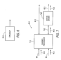
- FIG. 6 is a simplified block diagram of a helm apparatus of the embodiment of FIG. 5;
- FIG. 7 is a simplified block diagram of a rudder actuator controller of the embodiment of FIG. 5; and
- FIG. 8 is a fragmentary, simplified block diagram of the embodiment of FIG. 2 showing details of the stop and encoder mechanisms for one helm only and the rudder components.
- With reference to FIG. 1, a conventional marine steering system having multiple helms includes a
hydraulic cylinder 10, a first hydraulic helm and a second hydraulic helm indicated generally byreference characters hydraulic cylinder 10 operates to actuate a rudder to steer the marine vessel. The fisthydraulic helm 12 is connected in parallel to the secondhydraulic helm 14. - When a first vessel operator steers the first
hydraulic helm 12, aflow 16 of hydraulic fluid is produced. When a second operator simultaneously steers the secondhydraulic helm 14, aflow 18 is produced. Ahydraulic cylinder flow 20 equals the sum of theflow 16 and theflow 18. - If the first operator turns faster than the second operator, the
flow 16 is then greater than theflow 18 and dominates theflow 20 of thehydraulic cylinder 10. - This is the basic operation of a conventional multiple helm hydraulic marine steering system. One embodiment of the present invention provides an equivalent multiple helm functionality in a novel way in a steer-by-wire marine steering system, as described below.
- Now referring to FIG. 2, in a first embodiment of the present invention there is a
communication bus 22, which in this example is a Local Interconnect Network (LIN) bus. In other embodiments thecommunication bus 22 can be other types of communication buses, either wired or wireless, such as CAN, I2C, SPI, USB, RS232, Ethernet, wireless Ethernet, Bluetooth and Zigabee. Thecommunication bus 22 is used as a communication backbone for other elements in the multiple helm steer-by-wire steering system as will be shown below. - In the present embodiment, steer-by-wire helms, indicated generally by
reference numerals communication bus 22. In other embodiments any other number of steer-by-wire helms can be connected to the communication bus. The steer-by-wire helms 24 and 26 includesteering wheels helm controllers - A steering element, in this example a
rudder 32, is connected to arudder actuator 34. In alternative embodiments the rudder could be replaced by other steering means such as an inboard/outboard drive or an outboard motor. Therudder 32 operates to change the direction of the marine vessel and therudder actuator 34 changes the orientation of the rudder with respect to the marine vessel. Therudder actuator 34 is connected to arudder actuator controller 36 for controlling the rudder actuator. Therudder actuator 34 comprises asensor 33 that provides positional information about the rudder actuator. Therudder actuator controller 36 is connected to thecommunication bus 22. - Referring now to FIG. 3, each of the
helm controllers encoder 50, ahelm processor 52 and abus transceiver 54. The encoder is connected to thehelm processor 52 byconnection 56. Thehelm processor 52 is connected to the bus transceiver byconnection 58. In this example theconnections - Each of the
encoders 50 is responsive to itsrespective steering wheel connection 56. The helm signals are representative of the increment or decrement in the movement ofsteering wheels - The
helm processor 52 is a microcontroller in this example and comprises a data processing means and a data storage means. Thehelm processor 52 stores and executes software instructions of a control program. In other embodiments the helm processor can comprise a microprocessor and a memory. The memory can comprise a non-volatile memory, such as a Read Only Memory (ROM) or an Electrically Eraseable Programmable ROM (E2PROM), and a volatile memory such as a Random Access Memory (RAM) or other types of memory. - It is understood by those skilled in the art that in other examples the
helm controllers helm processor 52. - The control program of the
helm processor 52 includes instructions to receive the helm signals, in the form of quadrature signals in this example, from theencoder 50 and instructions to transmit the helm signals onto thecommunication bus 22. - As is understood by those familiar with the art, the
bus transceiver 54 electrically conditions any signal from thehelm processor 52 for transmission onto thecommunication bus 22. The bus transceiver also conditions signals from the communication bus for reception in thehelm processor 52. - Referring now to FIG. 4, the
rudder actuator controller 36 includes abus transceiver 70, arudder processor 72 and amotor driver 74 for therudder actuator 34. The bus transceiver is connected to the rudder processor byconnection 76. The rudder processor is connected to themotor driver 74 byconnection 78 and to therudder actuator 34 byconnection 80. The motor driver is connected to therudder actuator 34 byconnection 82. In this example theconnections motor driver 74 drives therudder 32 and thesensor 33 provides positional feedback information of therudder 32 over theconnection 80. - The operation of the
bus transceiver 70 is similar in principle to the operation ofbus transceiver 54 above. The bus transceiver electrically conditions signals from thecommunication bus 22 and from therudder processor 72. - The
helm processor 72 is a microcontroller in this example and comprises a data processing means and a data storage means. Thehelm processor 72 stores and executes software instructions of a control program. In other embodiments the helm processor can comprise a microprocessor and a memory. The memory can comprise a non-volatile memory, such as a Read Only Memory (ROM) or an Electrically Eraseable Programmable ROM (E2PROM), and a volatile memory such as a Random Access Memory (RAM) or other types of memory. - It is understood by those skilled in the art that in other examples the
rudder actuator controller 36 can include a programmable logic device or an ASIC instead of thehelm processor 72. - The control program of the
rudder processor 72 includes instructions to receive signals from thecommunication bus 22 viabus transceiver 70 and instructions to generate rudder signals in the form of motor driver signals indicated generally byreference numeral 84. The rudder signals are logical signals and are used to actuate therudder actuator 34. - The
motor driver 74 electrically conditions the rudder signals in the form of motor driver signals 84 from therudder processor 72 into rudder signals for therudder actuator 34, as indicated byreference numeral 42 in FIGS. 2 and 4. It is to be understood that the rudder signals are logical signals herein and can appear in different forms in different parts of the multiple steer by wire helm system. - Referring again to FIG. 2, in operation the
rudder 32 has a default position in which it allows the marine vessel to continue in its current direction. Thesteering wheels rudder 32. A clockwise or counterclockwise movement of either of thesteering wheels - The steer-by-wire helms 24 and 26 do not require information on the absolute position of the
rudder 32. Thehelms steering wheels controller 36 in order to provide rotational resistance to the steering wheels to effect steering feedback resistance. The steering resistance signals from thecontroller 36 are related to the position of therudder 32. - The
sensor 33 provides positional information of therudder 32 to therudder actuator controller 36. Therudder actuator controller 36 sends the steering resistance signals to thehelms communication bus 22 for controlling the steering feedback resistance applied to thesteering wheels rudder 32 approaches a maximum steered position, the steering feedback resistance applied to the steering wheel is experienced by the person as increased resistance in the direction of steering. When therudder 32 reaches the maximum steered position, the steering feedback resistance applied to the steering wheel prevents the person from steering the wheel further in that direction of steering. - Referring to FIG. 8, the
helm controller 29 also has a brake in the form of astop mechanism 94, adrive shaft 96 and stopelectronics 98, thehelm controller 31 having corresponding elements. Thestop mechanism 94 is similar to the stop mechanism described inUnited States Patent Application No. 10/926,327 drive shaft 94. Accordingly, the armature is rigidly connected to thedrive shaft 94. - When the
rudder 32 reaches the maximum steered position, i.e. a starboard or port hard-over position, thehelm processor 52 receives steering resistance signals from thecommunication bus 22 and accordingly applies a stop signal to thestop mechanism 94 through thestop electronics 98. The stop signal actuates the solenoid to force the plates together causing friction between the plates thereby stopping rotation of thedrive shaft 96. There is some play between the steeringdevice 28 and thedrive shaft 96, and since theencoder 50 detects movement of thesteering device 28, thehelm processor 52 can detect movement of the steering device away from the maximum steered position so that it can release the stop mechanism enabling the drive shaft to rotate away from the maximum steered position as well thereby providing steering decrement signals. - Another aspect of the present invention is instantaneous synchronization of
steering wheels steering wheel 28 is one quarter turn, i.e. 90 degrees, from end stop, and a person turns it one eighth of a full rotation towards end stop, then the wheel has one eighth of a turn remaining before reaching an end stop. The end stop occurs when the steering feedback resistance applied to the wheel prevents the wheel from turning in a certain direction, and which corresponds to a maximum steered position of therudder 32. Now, if that person next goes to thesteering wheel 30 and begins to turn it in the same direction in which thesteering wheel 28 was turned, then wheel 30 can turn at most one eighth of a turn before reaching the end stop. This is possible since therudder actuator controller 36 is aware of the absolute rudder position due to thesensor 33, and therefore thecontroller 36 can inform thehelms - The steer-by-wire helms 24 and 26 and the
rudder actuator controller 36 can operate in an accumulated steering manner. Referring back to FIG. 2, a first operator steers thesteering wheel 28 which causes the steer-by-wire helm 24 to generate ahelm signal 38 representative of the increment or decrement in the steering wheel. Thehelm signal 38 is directed onto thecommunication bus 22. Whenever the first operator changes the position of thesteering wheel 28 thehelm signal 38 is generated and is directed onto thecommunication bus 22. - Similarly, a second operator steers the
steering wheel 30 which causes the steer-by-wire helm 26 to generatehelm signal 40 which is correspondingly directed onto thecommunication bus 22. - The helm signals 38 and 40 are signed signals representative of an increment in steering, in which case they are positive in this example, or a decrement in steering, in which case they are negative in this example.
- The helm signals 38 and 40 are received by the
rudder actuator controller 36 whenever they are directed onto thecommunication bus 22. The control program of therudder processor 72 includes instructions to provide an aggregate signal equal to the accumulation of the helm signals 38 and 40. Therudder actuator controller 36 continuously receives the helm signals 38 and 40 and continuously updates the aggregate signal with the helm signal values. - The control program of the
rudder processor 72 periodically generates arudder signal 42, which is equivalent to the sum of the aggregate helm signal and a previous rudder signal. Therudder signal 42 is applied to therudder actuator 34 to actuate therudder 32. After therudder signal 42 is generated, the aggregate signal is reset to a zero value and the previous rudder signal is equated to the rudder signal. A mathematical expression for therudder signal 42 is symbolically stated as:
wherein θnew is the rudder signal, θprevious is the previous rudder signal, Δθ38 is thehelm signal 38, Δθ40 is thehelm signal 40 and ΣΔθ38 + ΣΔθ40 is the aggregate signal. - This embodiment simulates the operation of the conventional multiple helm hydraulic marine steering system using steer-by-wire helms 24 and 26. If the first operator steers more frequently than the second operator then there will be more helm signals 38 from the steer-by-
wire helm 24 than helm signals 40 from the steer-by-wire helm 26. Accordingly, the aggregate signal will be dominated by thehelm signal 38, and so will therudder signal 42. If the first operator steers faster than the second operator then the helm signals 38 from the steer-by-wire helm 24 will be greater in absolute value than the absolute value of helm signals 40 from the steer-by-wire helm 26. Accordingly, the aggregate signal, again, will be dominated by thehelm signal 38, and so will therudder signal 42. - The
communication bus 22 makes it easier to add additional helms in the marine steering system. In general, therudder signal 42 is defined as
wherein Δθi is a helm signal and where "i" is an index for the helms. - One concern about accumulating the helm signals 38 and 40 is that the
rudder signal 42 may direct therudder actuator 34 to steer too quickly. This concern may be solved by limiting the maximum rate of steering by the control program in therudder actuator controller 36 or, alternatively, by the size of therudder actuator 34. - This accumulating steering arrangement has the advantage of simplifying helm design. All helms can be physically identical. That is, no master helm is necessary, nor is a special master setup routine to configure the master helm. This simplifies manufacturing and the ordering process for the helm manufacturer and marine vessel builders.
- Taking control of the marine vessel is advantageously intuitive and quick in this embodiment. The user can grab the wheel of either helm and start steering, without having to log in or go through a transfer control routine as with prior art multiple helm systems. This improves the safety of operating the marine vessel.
- Alternatively, a variation of the accumulating steering is a "faster win" scenario. Instead of the control program of the
rudder processor 72 aggregating all helm signals from the multiple helms, the control program of therudder processor 72 uses the helm signal with the largest amplitude, the other helm signals being discarded. In this situation, the user who steers the wheel the fastest has control of the boat. - A mathematical expression for the
rudder signal 42 in the faster win scenario is symbolically stated as:
wherein θnew is the rudder signal, θprevious is the previous rudder signal, Δθ38 is thehelm signal 38, Δθ40 is thehelm signal 40 and max(Δθ38 + Δθ40) is the fastest helm signal. - The faster win scenario signifies that emergency movement is most likely with a higher rate of turn of the steering wheel. Additionally, adults tend to turn boats faster than children. The faster win scenario also advantageously ignores minor, unintentional movement from inactive helms, typically due to vibration or wind.
- An optional collision acknowledgement indication can be used with either the accumulating steering or faster win steering scenarios, warning users that multiple helms are attempting to steer the boat. This promotes a dialog among the helmsman to coordinate steering control of the boat.
- Referring now to FIG. 5, another embodiment of the present invention, wherein like parts to the previous embodiment have like reference numerals with an additional suffix ".2", includes helm apparatuses indicated generally by reference numeral 24.2 and 26.2. In other examples there can be any number of helm apparatuses. There is also a rudder 32.2, a rudder actuator 34.2 and a rudder actuator controller 36.2 for controlling the rudder actuator. As in the previous embodiment the apparatus may be used with other types of steering elements besides rudders.
- The helm apparatus 24.2 is directly connected to the rudder actuator controller 36.2 by
electrical connection 90. The helm apparatus 24.2 includes a steering device 28.2 and a helm controller 29.2. - The helm apparatus 26.2 is directly connected to the rudder actuator controller 36.2 by
electrical connection 92. The helm apparatus 26.2 includes a steering device 30.2 and a helm controller 31.2. - Referring now to FIG. 6, each of the helm controllers 29.2 and 31.2 includes an encoder 50.2. Each encoder 50.2 is connected directly to the rudder actuator controller 36.2. Each encoder 50.2 is responsive to one of the steering devices 28.2 and 30.2 and provides helm signals in the form of quadrature signals.
- Referring now to FIG. 7, the rudder actuator controller 36.2 includes a rudder processor 72.2 and a motor driver 74.2 for the rudder actuator 34.2. The rudder processor 72.2 is a microcontroller, in this example, and comprises a data processing means and a data storage means. The rudder processor 72.2 is connected to
electrical connections - The helm processor 72.2 stores and executes software instructions of a control program. In other embodiments the helm processor 72.2 can comprise a microprocessor and a memory. The memory can comprise a non-volatile memory, such as a Read Only Memory (ROM) or an Electrically Eraseable Programmable ROM (E2PROM), and a volatile memory such as a Random Access Memory (RAM).
- It is understood by those skilled in the art that in other examples the rudder actuator controller 36.2 can include a programmable logic device or an ASIC instead of the rudder processor 72.2.
- The control program of the rudder processor 72.2 includes instructions to receive the helm signals, in the form of quadrature signals in this example, from
connections - This embodiment operates in a similar manner to the previous embodiments, i.e. with aggregate steering or faster win steering, therefore the operation will not be explained again.
- This embodiment has the advantage of being more cost effective since the
connections communication bus 22 of the previous embodiment. However, the previous embodiment has the advantage of being more robust, less coupled and more functionality, i.e. control signals can go between the helms and therudder actuator controller 36, and between the rudder actuator controller and each of the helms. - It will be understood by someone skilled in the art that many of the details provided above are by way of example only and are not intended to limit the scope of the invention which is to be interpreted with reference to the following claims.
Claims (24)
- A steering apparatus for a marine craft, the steering apparatus comprising:a plurality of helm apparatuses, each said helm apparatus including a steering device, each said helm apparatus providing helm signals indicative of incremental and decremental movement of the steering device thereof;a steering element;a steering element actuator; anda control means for controlling the steering element actuator, the control means being responsive to said helm signals of each of the helm apparatuses and providing steering signals to the steering element actuator to steer the steering element in accordance with movement of the steering devices of the helm apparatuses.
- The steering apparatus as claimed in claim 1, wherein the steering element is a rudder, the steering element actuator is a rudder actuator and the steering signals are rudder signals.
- The steering apparatus as claimed in claim 1, wherein said steering signals are derived from said helm signals from one of said helm apparatuses which is steered fastest when a plurality of said helm apparatuses is simultaneously steered.
- The steering apparatus as claimed in claim 1, wherein said rudder signals are derived from aggregating said helm signals of each of the helm apparatuses.
- The steering apparatus as claimed in claim 1, wherein the apparatus further includes a communication bus, the control means and each of the helm apparatuses being coupled to the communication bus, each of the helm apparatuses transmitting respective helm signals onto the communication bus and the control means receiving the helm signals from the communication bus.
- The steering apparatus as claimed in claim 1, wherein the control means includes at least one of a data processing means, a data storage means, a programmable logic device and an application specific integrated circuit.
- The steering apparatus as claimed in claim 6, wherein the control means further includes a means for deriving said steering signals from said helm signals from one of said helm apparatuses which is steered fastest when a plurality of said helm apparatuses is simultaneously steered.
- The steering apparatus as claimed in claim 6, wherein the control means further includes a means for deriving said steering signals from aggregating said helm signals of each of the helm apparatuses.
- The steering apparatus of claim 5, wherein each said helm apparatus further includes:an encoder responsive to the steering device and providing the helm signals;at least one of a data processing means, a data storage means, a programmable logic device and an application specific integrated circuit; anda means for receiving the helm signals from the encoder and transmitting said helm signals onto the communication bus.
- The steering apparatus of claim 5, wherein the communication bus is at least one of a wired bus and a wireless bus.
- The steering apparatus of claim 5, wherein the communication bus is at least one of a Local Interconnect Network (LIN) bus, a Controller Area Network (CAN) bus and an Ethernet bus.
- The steering apparatus of claim 1, wherein the steering device is a steering wheel.
- The steering apparatus of claim 1, wherein each of the helm apparatuses further includes an encoder, the encoder being responsive to the steering device and providing the helm signals.
- The steering apparatus of claim 5, wherein each said helm apparatus includes a collision acknowledgment means for indicating two or more of the plurality of helm apparatuses are attempting to steer the marine craft.
- The steering apparatus as claimed in claim 1, wherein each of the helm apparatuses are connected to the control means.
- The steering apparatus as claimed in claim 1, wherein the apparatus further includes a sensor for detecting the position of the steering element, said sensor providing position information of the steering element to the control means.
- The steering apparatus as claimed in claim 16, wherein the control means includes means for controlling the rotational resistance of each of the steering devices.
- The steering apparatus as claimed in claim 1, wherein each of the helm apparatuses has a stop mechanism and a sensor, the stop mechanism being actuated when the steering element approaches a limit of travel, causing the stop mechanism to engage the steering device to stop further rotation of the steering device in a first rotational direction, corresponding to rotational movement towards the limit of travel, rotational play being provided between the steering device and the stop mechanism, whereby the steering device can be rotated a limited amount, as sensed by the sensor, when the stop mechanism is fully engaged, the stop mechanism being released from engagement with the steering device when the sensor senses that the steering device is rotated, as permitted by said play, in a second rotational direction which is opposite the first rotational direction.
- A method of steering a marine craft having a plurality of helms and a steering element, each said helm having a steering device, the method comprising the steps of:generating helm signals from the steering devices, the helm signals being indicative of the incremental and decremental movement of the steering devices;generating steering signals that are derived from said helm signals; andactuating the steering element with the steering signals to effect steering of the marine craft.
- The method of steering as claimed in claim 19, wherein the steering signals are derived from said helm signals from one of said steering devices which is steered fastest when a plurality of said steering devices is simultaneously steered.
- The method of steering as claimed in claim 19, wherein the steering signals are derived from aggregating said helm signals of each of the steering devices.
- The method of steering as claimed in claim 19, wherein the method further including the steps of:generating position signals representative of the position of the steering element;generating steering resistance signals from the position signals; andproviding steering feedback resistance to the steering devices based on the steering resistance signals.
- The method of steering as claimed in claim 22, wherein the step of providing steering feedback resistance includes the step of synchronizing the steering resistance signals with each of the helms.
- The method of steering as claimed in claim 22, wherein the method further includes the step of synchronizing the steering feedback resistance of each of the steering devices relative the steering resistance signals.
Applications Claiming Priority (1)
| Application Number | Priority Date | Filing Date | Title |
|---|---|---|---|
| US11/236,568 US7258072B2 (en) | 2004-08-26 | 2005-09-28 | Multiple steer by wire helm system |
Publications (3)
| Publication Number | Publication Date |
|---|---|
| EP1770008A2 true EP1770008A2 (en) | 2007-04-04 |
| EP1770008A3 EP1770008A3 (en) | 2011-08-24 |
| EP1770008B1 EP1770008B1 (en) | 2017-06-14 |
Family
ID=37603254
Family Applications (1)
| Application Number | Title | Priority Date | Filing Date |
|---|---|---|---|
| EP06121031.6A Active EP1770008B1 (en) | 2005-09-28 | 2006-09-21 | Multiple steer by wire helm system |
Country Status (3)
| Country | Link |
|---|---|
| US (1) | US7258072B2 (en) |
| EP (1) | EP1770008B1 (en) |
| JP (1) | JP5105464B2 (en) |
Cited By (9)
| Publication number | Priority date | Publication date | Assignee | Title |
|---|---|---|---|---|
| WO2008125614A3 (en) * | 2007-04-12 | 2009-01-15 | Deere & Co | Vehicle communication system, and method for the operation of a communication system |
| DE102007048061A1 (en) | 2007-10-05 | 2009-04-09 | Zf Friedrichshafen Ag | Steering actuator for a steer-by-wire vessel control system and method for operating the steering actuator |
| DE102007048055A1 (en) | 2007-10-05 | 2009-04-09 | Zf Friedrichshafen Ag | A method of operating a steering unit for a steer-by-wire vessel control system |
| DE102007048077A1 (en) | 2007-10-05 | 2009-04-09 | Zf Friedrichshafen Ag | Steering unit for a steer-by-wire ship control system and method for operating the steering unit |
| US8265830B2 (en) | 2007-09-28 | 2012-09-11 | Yamaha Hatsudoki Kabushiki Kaisha | Steering control method, steering control device, and watercraft |
| US8376793B2 (en) | 2007-10-05 | 2013-02-19 | Zf Friedrichshafen Ag | Method for controlling a surface drive for a watercraft in the upper speed range |
| US8376792B2 (en) | 2007-10-05 | 2013-02-19 | Zf Friedrichshafen Ag | Method for controlling a watercraft having a surface drive |
| US8376791B2 (en) | 2007-10-05 | 2013-02-19 | Zf Friedrichshafen Ag | Method for controlling a surface drive for a watercraft |
| CN103093513A (en) * | 2011-10-27 | 2013-05-08 | 西门子公司 | Method for exchanging data in a transport system and vehicle control system |
Families Citing this family (19)
| Publication number | Priority date | Publication date | Assignee | Title |
|---|---|---|---|---|
| US20030150366A1 (en) * | 2002-02-13 | 2003-08-14 | Kaufmann Timothy W. | Watercraft steer-by-wire system |
| NO324369B1 (en) * | 2006-04-26 | 2007-10-01 | Sleipner Motor As | Marine Power Steering System and System |
| EP1995653A1 (en) * | 2007-05-22 | 2008-11-26 | Abb Research Ltd. | System for controlling an automation process |
| US8677920B1 (en) * | 2007-08-30 | 2014-03-25 | Ocom Technology LLC | Underwater vehicle |
| JP2009083595A (en) * | 2007-09-28 | 2009-04-23 | Yamaha Marine Co Ltd | Steering control method, steering control device and watercraft |
| US8007330B2 (en) * | 2008-04-08 | 2011-08-30 | Teleflex Canada Inc. | Steering apparatus with integrated steering actuator |
| DE102008049126B3 (en) * | 2008-09-26 | 2010-04-08 | Raytheon Anschütz Gmbh | Ship rudder control / autopilot with a CAN bus |
| JP5203145B2 (en) * | 2008-11-12 | 2013-06-05 | ヤマハ発動機株式会社 | Marine propulsion system |
| JP5337730B2 (en) * | 2010-01-29 | 2013-11-06 | 本田技研工業株式会社 | Wireless communication system |
| JP5019404B2 (en) * | 2010-08-19 | 2012-09-05 | 日本発條株式会社 | Outboard motor steering system |
| US8939807B2 (en) | 2012-01-20 | 2015-01-27 | Bartley D. Jones | Propeller protection apparatus |
| EP3770061B1 (en) * | 2012-02-14 | 2022-08-24 | Marine Canada Acquisition Inc. | A steering system for a marine vessel |
| EP3006327B1 (en) | 2014-10-06 | 2018-05-16 | ABB Schweiz AG | A control system for a ship |
| US20170029084A1 (en) * | 2015-07-28 | 2017-02-02 | Steering Solutions Ip Holding Corporation | Column based electric assist marine power steering |
| US10940927B2 (en) * | 2018-05-14 | 2021-03-09 | Marine Canada Acquistion Inc. | Electric actuator for a marine vessel |
| CN111776190B (en) * | 2020-06-22 | 2022-04-12 | 锦州航星船舶科技有限公司 | A digital rudder angle feedback indication system and control method |
| US12326735B2 (en) | 2021-07-23 | 2025-06-10 | Seakeeper, Inc. | Dynamic active control system with engine control |
| WO2023023363A1 (en) | 2021-08-19 | 2023-02-23 | Seakeeper, Inc. | Commissioning strategy |
| US12485998B2 (en) | 2021-08-23 | 2025-12-02 | Seakeeper, Inc. | Mounting plate assembly and system |
Citations (4)
| Publication number | Priority date | Publication date | Assignee | Title |
|---|---|---|---|---|
| US5107424A (en) | 1990-03-05 | 1992-04-21 | Sperry Marine Inc. | Configurable marine steering system |
| US6273771B1 (en) | 2000-03-17 | 2001-08-14 | Brunswick Corporation | Control system for a marine vessel |
| US6311634B1 (en) | 1998-12-30 | 2001-11-06 | Nautamatic Marine Systems, Inc. | Synchronizing multiple steering inputs to marine rudder/steering actuators |
| US20050229834A1 (en) | 2003-08-29 | 2005-10-20 | Wong Ray T | Steer by wire helm |
Family Cites Families (19)
| Publication number | Priority date | Publication date | Assignee | Title |
|---|---|---|---|---|
| US3695205A (en) | 1970-11-05 | 1972-10-03 | Sperry Rand Corp | Combination lever ship's steering system |
| US3949696A (en) | 1972-06-21 | 1976-04-13 | Tokyo Keiki Company Limited | Marine steering arrangement |
| US4020713A (en) * | 1974-10-16 | 1977-05-03 | Incom International Inc. | Station control selection system |
| US4120258A (en) | 1976-10-13 | 1978-10-17 | Sperry Rand Corporation | Variable ratio helm |
| SE465160B (en) * | 1989-12-14 | 1991-08-05 | Volvo Penta Ab | ELECTROMAGNETIC CONTROL DEVICE FOR BAATAR |
| JPH11334630A (en) | 1998-05-22 | 1999-12-07 | Koyo Seiko Co Ltd | Power steering unit |
| FI107042B (en) | 1998-09-14 | 2001-05-31 | Abb Azipod Oy | Turning a propulsion unit |
| SE515685C2 (en) | 1998-11-26 | 2001-09-24 | Volvo Penta Ab | Steering servo, eg for boats |
| DE10057242A1 (en) | 2000-11-18 | 2002-05-29 | Bosch Gmbh Robert | Coupling for a steer-by-wire steering system |
| US6575263B2 (en) | 2001-04-26 | 2003-06-10 | Eaton Corporation | Torque device for electronic steer-by wire steering systems |
| US6817437B2 (en) | 2001-06-19 | 2004-11-16 | Delphi Technologies, Inc. | Steer-by wire handwheel actuator |
| CA2350910A1 (en) | 2001-06-20 | 2002-12-20 | Kevin Tuer | Reconfigurable dashboard system |
| US6382122B1 (en) * | 2001-06-22 | 2002-05-07 | Brunswick Corporation | Method for initializing a marine vessel control system |
| CA2353053C (en) | 2001-07-13 | 2004-07-06 | Jastram Engineering Ltd. | Marine steering system having dual hydraulic and electronic output |
| US7037150B2 (en) * | 2001-09-28 | 2006-05-02 | Morvillo Robert A | Method and apparatus for controlling a waterjet-driven marine vessel |
| US20030150366A1 (en) * | 2002-02-13 | 2003-08-14 | Kaufmann Timothy W. | Watercraft steer-by-wire system |
| US6843195B2 (en) | 2003-01-17 | 2005-01-18 | Honda Motor Co., Ltd. | Outboard motor steering system |
| JP4303149B2 (en) * | 2004-03-09 | 2009-07-29 | ヤマハ発動機株式会社 | Electric steering device |
| ITSV20040023A1 (en) * | 2004-05-17 | 2004-08-17 | Ultraflex Spa | SYSTEM AND METHOD FOR DIRECTIONAL CONTROL OF VESSELS, SUCH AS BOATS OR SIMILAR |
-
2005
- 2005-09-28 US US11/236,568 patent/US7258072B2/en not_active Expired - Lifetime
-
2006
- 2006-09-21 EP EP06121031.6A patent/EP1770008B1/en active Active
- 2006-09-26 JP JP2006259889A patent/JP5105464B2/en active Active
Patent Citations (4)
| Publication number | Priority date | Publication date | Assignee | Title |
|---|---|---|---|---|
| US5107424A (en) | 1990-03-05 | 1992-04-21 | Sperry Marine Inc. | Configurable marine steering system |
| US6311634B1 (en) | 1998-12-30 | 2001-11-06 | Nautamatic Marine Systems, Inc. | Synchronizing multiple steering inputs to marine rudder/steering actuators |
| US6273771B1 (en) | 2000-03-17 | 2001-08-14 | Brunswick Corporation | Control system for a marine vessel |
| US20050229834A1 (en) | 2003-08-29 | 2005-10-20 | Wong Ray T | Steer by wire helm |
Cited By (17)
| Publication number | Priority date | Publication date | Assignee | Title |
|---|---|---|---|---|
| EP2335981A1 (en) | 2007-04-12 | 2011-06-22 | Deere & Company | Communication system for an agricultural vehicle |
| CN101652270B (en) * | 2007-04-12 | 2014-06-25 | 迪尔公司 | Vehicle communication system and method for operating the communication system |
| WO2008125614A3 (en) * | 2007-04-12 | 2009-01-15 | Deere & Co | Vehicle communication system, and method for the operation of a communication system |
| US8265830B2 (en) | 2007-09-28 | 2012-09-11 | Yamaha Hatsudoki Kabushiki Kaisha | Steering control method, steering control device, and watercraft |
| US8176865B2 (en) | 2007-10-05 | 2012-05-15 | Zf Friedrichshafen Ag | Steering actuator for a steer-by-wire ship's control system and method for operating said steering actuator |
| WO2009047131A2 (en) | 2007-10-05 | 2009-04-16 | Zf Friedrichshafen Ag | Steering actuator for a steer-by-wire ship's control system and method for operating said steering actuator |
| WO2009047131A3 (en) * | 2007-10-05 | 2010-08-05 | Zf Friedrichshafen Ag | Steering actuator for a steer-by-wire ship's control system and method for operating said steering actuator |
| WO2009047135A2 (en) | 2007-10-05 | 2009-04-16 | Zf Friedrichshafen Ag | Method for operating a steering unit for a steer-by-wire ship's control system |
| DE102007048077A1 (en) | 2007-10-05 | 2009-04-09 | Zf Friedrichshafen Ag | Steering unit for a steer-by-wire ship control system and method for operating the steering unit |
| US8255102B2 (en) | 2007-10-05 | 2012-08-28 | Zf Friedrichshafen Ag | Steering unit for a steer-by-wire ship's control system and method for operating the steering unit |
| DE102007048055A1 (en) | 2007-10-05 | 2009-04-09 | Zf Friedrichshafen Ag | A method of operating a steering unit for a steer-by-wire vessel control system |
| US8376793B2 (en) | 2007-10-05 | 2013-02-19 | Zf Friedrichshafen Ag | Method for controlling a surface drive for a watercraft in the upper speed range |
| US8376792B2 (en) | 2007-10-05 | 2013-02-19 | Zf Friedrichshafen Ag | Method for controlling a watercraft having a surface drive |
| US8376791B2 (en) | 2007-10-05 | 2013-02-19 | Zf Friedrichshafen Ag | Method for controlling a surface drive for a watercraft |
| DE102007048061A1 (en) | 2007-10-05 | 2009-04-09 | Zf Friedrichshafen Ag | Steering actuator for a steer-by-wire vessel control system and method for operating the steering actuator |
| CN103093513A (en) * | 2011-10-27 | 2013-05-08 | 西门子公司 | Method for exchanging data in a transport system and vehicle control system |
| CN103093513B (en) * | 2011-10-27 | 2016-11-02 | 西门子公司 | Method and vehicle control system for data exchange in a transport system |
Also Published As
| Publication number | Publication date |
|---|---|
| EP1770008A3 (en) | 2011-08-24 |
| EP1770008B1 (en) | 2017-06-14 |
| JP2007091213A (en) | 2007-04-12 |
| US7258072B2 (en) | 2007-08-21 |
| US20060042532A1 (en) | 2006-03-02 |
| JP5105464B2 (en) | 2012-12-26 |
Similar Documents
| Publication | Publication Date | Title |
|---|---|---|
| EP1770008B1 (en) | Multiple steer by wire helm system | |
| JP4331628B2 (en) | Ship propulsion device steering device and ship | |
| CN109890685B (en) | Method for controlling a steer-by-wire steering system with reduced feedback in an automatic drive mode | |
| US7028804B2 (en) | Steering angle neutral position detection error protecting method and detection error protecting apparatus | |
| CN100497065C (en) | Vehicle steering system | |
| US7970514B2 (en) | Vehicle adapted for disabled people | |
| US8046121B2 (en) | Watercraft steering device and watercraft | |
| JPH11255132A (en) | Vehicle steering system | |
| KR101422499B1 (en) | Steering apparatus for ship and control method threrof | |
| US20230192186A1 (en) | Steer-by-wire steering system for a motor vehicle | |
| US20170174258A1 (en) | Steering control device, steering control system, steering control method, and computer readable medium storing steering control program | |
| EP1923308A3 (en) | Steering system for a watercraft | |
| WO2008059731A1 (en) | Vehicle steering device | |
| JP5132132B2 (en) | Ship steering device and ship | |
| EP1889781B1 (en) | Watercraft control apparatus | |
| JP2007245821A (en) | Vehicle steering unit | |
| JP2008030591A (en) | Braking control device and method thereof | |
| KR970016565A (en) | Unmanned driving test system of test car | |
| CN117222569A (en) | Driver torque measurement and steering angle measurement in Torque Superposition Steering (TOS) | |
| KR20240042751A (en) | Steer-by-wire system and method for controlling steering in case of SFA breakdown | |
| JP4558582B2 (en) | Vehicle operating device | |
| AU2023289042B2 (en) | Vehicle control arrangement | |
| JPH10258750A (en) | Steering control device | |
| JP4594129B2 (en) | Vehicle steering device | |
| CN111791942B (en) | Electronically controlled angle steering gear assembly |
Legal Events
| Date | Code | Title | Description |
|---|---|---|---|
| PUAI | Public reference made under article 153(3) epc to a published international application that has entered the european phase |
Free format text: ORIGINAL CODE: 0009012 |
|
| AK | Designated contracting states |
Kind code of ref document: A2 Designated state(s): AT BE BG CH CY CZ DE DK EE ES FI FR GB GR HU IE IS IT LI LT LU LV MC NL PL PT RO SE SI SK TR |
|
| AX | Request for extension of the european patent |
Extension state: AL BA HR MK YU |
|
| PUAL | Search report despatched |
Free format text: ORIGINAL CODE: 0009013 |
|
| AK | Designated contracting states |
Kind code of ref document: A3 Designated state(s): AT BE BG CH CY CZ DE DK EE ES FI FR GB GR HU IE IS IT LI LT LU LV MC NL PL PT RO SE SI SK TR |
|
| AX | Request for extension of the european patent |
Extension state: AL BA HR MK RS |
|
| RIC1 | Information provided on ipc code assigned before grant |
Ipc: B63H 25/02 20060101AFI20110721BHEP |
|
| 17P | Request for examination filed |
Effective date: 20120223 |
|
| AKX | Designation fees paid |
Designated state(s): AT BE BG CH CY LI |
|
| RAP1 | Party data changed (applicant data changed or rights of an application transferred) |
Owner name: MARINE CANADA ACQUISITION INC. |
|
| RBV | Designated contracting states (corrected) |
Designated state(s): AT BE BG CH CY CZ LI |
|
| REG | Reference to a national code |
Ref country code: DE Ref legal event code: R108 Ref document number: 602006052771 Country of ref document: DE Effective date: 20120502 Ref country code: DE Ref legal event code: R108 Effective date: 20120502 |
|
| RBV | Designated contracting states (corrected) |
Designated state(s): AT BE BG CH CY CZ DE DK EE ES FI FR GB GR HU IE IS IT LI LT LU LV MC NL PL PT RO SE SI SK TR |
|
| 17Q | First examination report despatched |
Effective date: 20130710 |
|
| GRAP | Despatch of communication of intention to grant a patent |
Free format text: ORIGINAL CODE: EPIDOSNIGR1 |
|
| INTG | Intention to grant announced |
Effective date: 20170109 |
|
| GRAS | Grant fee paid |
Free format text: ORIGINAL CODE: EPIDOSNIGR3 |
|
| GRAA | (expected) grant |
Free format text: ORIGINAL CODE: 0009210 |
|
| AK | Designated contracting states |
Kind code of ref document: B1 Designated state(s): AT BE BG CH CY CZ DE DK EE ES FI FR GB GR HU IE IS IT LI LT LU LV MC NL PL PT RO SE SI SK TR |
|
| REG | Reference to a national code |
Ref country code: GB Ref legal event code: FG4D |
|
| REG | Reference to a national code |
Ref country code: AT Ref legal event code: REF Ref document number: 900699 Country of ref document: AT Kind code of ref document: T Effective date: 20170615 Ref country code: CH Ref legal event code: EP |
|
| REG | Reference to a national code |
Ref country code: IE Ref legal event code: FG4D |
|
| REG | Reference to a national code |
Ref country code: DE Ref legal event code: R096 Ref document number: 602006052771 Country of ref document: DE |
|
| REG | Reference to a national code |
Ref country code: FR Ref legal event code: PLFP Year of fee payment: 12 |
|
| REG | Reference to a national code |
Ref country code: SE Ref legal event code: TRGR |
|
| REG | Reference to a national code |
Ref country code: NL Ref legal event code: FP |
|
| REG | Reference to a national code |
Ref country code: LT Ref legal event code: MG4D |
|
| PG25 | Lapsed in a contracting state [announced via postgrant information from national office to epo] |
Ref country code: LT Free format text: LAPSE BECAUSE OF FAILURE TO SUBMIT A TRANSLATION OF THE DESCRIPTION OR TO PAY THE FEE WITHIN THE PRESCRIBED TIME-LIMIT Effective date: 20170614 Ref country code: GR Free format text: LAPSE BECAUSE OF FAILURE TO SUBMIT A TRANSLATION OF THE DESCRIPTION OR TO PAY THE FEE WITHIN THE PRESCRIBED TIME-LIMIT Effective date: 20170915 Ref country code: ES Free format text: LAPSE BECAUSE OF FAILURE TO SUBMIT A TRANSLATION OF THE DESCRIPTION OR TO PAY THE FEE WITHIN THE PRESCRIBED TIME-LIMIT Effective date: 20170614 |
|
| REG | Reference to a national code |
Ref country code: AT Ref legal event code: MK05 Ref document number: 900699 Country of ref document: AT Kind code of ref document: T Effective date: 20170614 |
|
| PG25 | Lapsed in a contracting state [announced via postgrant information from national office to epo] |
Ref country code: LV Free format text: LAPSE BECAUSE OF FAILURE TO SUBMIT A TRANSLATION OF THE DESCRIPTION OR TO PAY THE FEE WITHIN THE PRESCRIBED TIME-LIMIT Effective date: 20170614 Ref country code: BG Free format text: LAPSE BECAUSE OF FAILURE TO SUBMIT A TRANSLATION OF THE DESCRIPTION OR TO PAY THE FEE WITHIN THE PRESCRIBED TIME-LIMIT Effective date: 20170914 |
|
| PG25 | Lapsed in a contracting state [announced via postgrant information from national office to epo] |
Ref country code: CZ Free format text: LAPSE BECAUSE OF FAILURE TO SUBMIT A TRANSLATION OF THE DESCRIPTION OR TO PAY THE FEE WITHIN THE PRESCRIBED TIME-LIMIT Effective date: 20170614 Ref country code: EE Free format text: LAPSE BECAUSE OF FAILURE TO SUBMIT A TRANSLATION OF THE DESCRIPTION OR TO PAY THE FEE WITHIN THE PRESCRIBED TIME-LIMIT Effective date: 20170614 Ref country code: RO Free format text: LAPSE BECAUSE OF FAILURE TO SUBMIT A TRANSLATION OF THE DESCRIPTION OR TO PAY THE FEE WITHIN THE PRESCRIBED TIME-LIMIT Effective date: 20170614 Ref country code: AT Free format text: LAPSE BECAUSE OF FAILURE TO SUBMIT A TRANSLATION OF THE DESCRIPTION OR TO PAY THE FEE WITHIN THE PRESCRIBED TIME-LIMIT Effective date: 20170614 Ref country code: SK Free format text: LAPSE BECAUSE OF FAILURE TO SUBMIT A TRANSLATION OF THE DESCRIPTION OR TO PAY THE FEE WITHIN THE PRESCRIBED TIME-LIMIT Effective date: 20170614 |
|
| PG25 | Lapsed in a contracting state [announced via postgrant information from national office to epo] |
Ref country code: PL Free format text: LAPSE BECAUSE OF FAILURE TO SUBMIT A TRANSLATION OF THE DESCRIPTION OR TO PAY THE FEE WITHIN THE PRESCRIBED TIME-LIMIT Effective date: 20170614 Ref country code: IS Free format text: LAPSE BECAUSE OF FAILURE TO SUBMIT A TRANSLATION OF THE DESCRIPTION OR TO PAY THE FEE WITHIN THE PRESCRIBED TIME-LIMIT Effective date: 20171014 |
|
| REG | Reference to a national code |
Ref country code: DE Ref legal event code: R097 Ref document number: 602006052771 Country of ref document: DE |
|
| PLBE | No opposition filed within time limit |
Free format text: ORIGINAL CODE: 0009261 |
|
| STAA | Information on the status of an ep patent application or granted ep patent |
Free format text: STATUS: NO OPPOSITION FILED WITHIN TIME LIMIT |
|
| PG25 | Lapsed in a contracting state [announced via postgrant information from national office to epo] |
Ref country code: DK Free format text: LAPSE BECAUSE OF FAILURE TO SUBMIT A TRANSLATION OF THE DESCRIPTION OR TO PAY THE FEE WITHIN THE PRESCRIBED TIME-LIMIT Effective date: 20170614 |
|
| REG | Reference to a national code |
Ref country code: CH Ref legal event code: PL |
|
| 26N | No opposition filed |
Effective date: 20180315 |
|
| PG25 | Lapsed in a contracting state [announced via postgrant information from national office to epo] |
Ref country code: MC Free format text: LAPSE BECAUSE OF FAILURE TO SUBMIT A TRANSLATION OF THE DESCRIPTION OR TO PAY THE FEE WITHIN THE PRESCRIBED TIME-LIMIT Effective date: 20170614 |
|
| REG | Reference to a national code |
Ref country code: IE Ref legal event code: MM4A |
|
| REG | Reference to a national code |
Ref country code: BE Ref legal event code: MM Effective date: 20170930 |
|
| PG25 | Lapsed in a contracting state [announced via postgrant information from national office to epo] |
Ref country code: LU Free format text: LAPSE BECAUSE OF NON-PAYMENT OF DUE FEES Effective date: 20170921 |
|
| PG25 | Lapsed in a contracting state [announced via postgrant information from national office to epo] |
Ref country code: LI Free format text: LAPSE BECAUSE OF NON-PAYMENT OF DUE FEES Effective date: 20170930 Ref country code: IE Free format text: LAPSE BECAUSE OF NON-PAYMENT OF DUE FEES Effective date: 20170921 Ref country code: CH Free format text: LAPSE BECAUSE OF NON-PAYMENT OF DUE FEES Effective date: 20170930 |
|
| PG25 | Lapsed in a contracting state [announced via postgrant information from national office to epo] |
Ref country code: BE Free format text: LAPSE BECAUSE OF NON-PAYMENT OF DUE FEES Effective date: 20170930 Ref country code: SI Free format text: LAPSE BECAUSE OF FAILURE TO SUBMIT A TRANSLATION OF THE DESCRIPTION OR TO PAY THE FEE WITHIN THE PRESCRIBED TIME-LIMIT Effective date: 20170614 |
|
| REG | Reference to a national code |
Ref country code: FR Ref legal event code: PLFP Year of fee payment: 13 |
|
| PG25 | Lapsed in a contracting state [announced via postgrant information from national office to epo] |
Ref country code: HU Free format text: LAPSE BECAUSE OF FAILURE TO SUBMIT A TRANSLATION OF THE DESCRIPTION OR TO PAY THE FEE WITHIN THE PRESCRIBED TIME-LIMIT; INVALID AB INITIO Effective date: 20060921 |
|
| PG25 | Lapsed in a contracting state [announced via postgrant information from national office to epo] |
Ref country code: CY Free format text: LAPSE BECAUSE OF NON-PAYMENT OF DUE FEES Effective date: 20170614 |
|
| PG25 | Lapsed in a contracting state [announced via postgrant information from national office to epo] |
Ref country code: TR Free format text: LAPSE BECAUSE OF FAILURE TO SUBMIT A TRANSLATION OF THE DESCRIPTION OR TO PAY THE FEE WITHIN THE PRESCRIBED TIME-LIMIT Effective date: 20170614 |
|
| PG25 | Lapsed in a contracting state [announced via postgrant information from national office to epo] |
Ref country code: PT Free format text: LAPSE BECAUSE OF FAILURE TO SUBMIT A TRANSLATION OF THE DESCRIPTION OR TO PAY THE FEE WITHIN THE PRESCRIBED TIME-LIMIT Effective date: 20170614 |
|
| PGFP | Annual fee paid to national office [announced via postgrant information from national office to epo] |
Ref country code: NL Payment date: 20210813 Year of fee payment: 16 |
|
| PGFP | Annual fee paid to national office [announced via postgrant information from national office to epo] |
Ref country code: SE Payment date: 20210816 Year of fee payment: 16 |
|
| REG | Reference to a national code |
Ref country code: SE Ref legal event code: EUG |
|
| REG | Reference to a national code |
Ref country code: NL Ref legal event code: MM Effective date: 20221001 |
|
| PG25 | Lapsed in a contracting state [announced via postgrant information from national office to epo] |
Ref country code: NL Free format text: LAPSE BECAUSE OF NON-PAYMENT OF DUE FEES Effective date: 20221001 |
|
| P01 | Opt-out of the competence of the unified patent court (upc) registered |
Effective date: 20230526 |
|
| PG25 | Lapsed in a contracting state [announced via postgrant information from national office to epo] |
Ref country code: SE Free format text: LAPSE BECAUSE OF NON-PAYMENT OF DUE FEES Effective date: 20220922 |
|
| PGFP | Annual fee paid to national office [announced via postgrant information from national office to epo] |
Ref country code: FI Payment date: 20250805 Year of fee payment: 20 |
|
| PGFP | Annual fee paid to national office [announced via postgrant information from national office to epo] |
Ref country code: DE Payment date: 20250806 Year of fee payment: 20 |
|
| PGFP | Annual fee paid to national office [announced via postgrant information from national office to epo] |
Ref country code: IT Payment date: 20250708 Year of fee payment: 20 |
|
| PGFP | Annual fee paid to national office [announced via postgrant information from national office to epo] |
Ref country code: GB Payment date: 20250805 Year of fee payment: 20 |
|
| PGFP | Annual fee paid to national office [announced via postgrant information from national office to epo] |
Ref country code: FR Payment date: 20250807 Year of fee payment: 20 |