EP1772342A2 - Temperatur-Überwachungsvorrichtung für Radsatzlager - Google Patents
Temperatur-Überwachungsvorrichtung für Radsatzlager Download PDFInfo
- Publication number
- EP1772342A2 EP1772342A2 EP06020661A EP06020661A EP1772342A2 EP 1772342 A2 EP1772342 A2 EP 1772342A2 EP 06020661 A EP06020661 A EP 06020661A EP 06020661 A EP06020661 A EP 06020661A EP 1772342 A2 EP1772342 A2 EP 1772342A2
- Authority
- EP
- European Patent Office
- Prior art keywords
- housing
- acceleration sensor
- threshold
- monitoring device
- evaluation unit
- Prior art date
- Legal status (The legal status is an assumption and is not a legal conclusion. Google has not performed a legal analysis and makes no representation as to the accuracy of the status listed.)
- Granted
Links
Images
Classifications
-
- B—PERFORMING OPERATIONS; TRANSPORTING
- B61—RAILWAYS
- B61L—GUIDING RAILWAY TRAFFIC; ENSURING THE SAFETY OF RAILWAY TRAFFIC
- B61L1/00—Devices along the route controlled by interaction with the vehicle or train
- B61L1/20—Safety arrangements for preventing or indicating malfunction of the device, e.g. by leakage current, by lightning
-
- B—PERFORMING OPERATIONS; TRANSPORTING
- B61—RAILWAYS
- B61K—AUXILIARY EQUIPMENT SPECIALLY ADAPTED FOR RAILWAYS, NOT OTHERWISE PROVIDED FOR
- B61K9/00—Railway vehicle profile gauges; Detecting or indicating overheating of components; Apparatus on locomotives or cars to indicate bad track sections; General design of track recording vehicles
- B61K9/04—Detectors for indicating the overheating of axle bearings and the like, e.g. associated with the brake system for applying the brakes in case of a fault
-
- B—PERFORMING OPERATIONS; TRANSPORTING
- B61—RAILWAYS
- B61L—GUIDING RAILWAY TRAFFIC; ENSURING THE SAFETY OF RAILWAY TRAFFIC
- B61L23/00—Control, warning or like safety means along the route or between vehicles or trains
Definitions
- the invention relates to a device for monitoring the temperature of the wheelset bearing of passing rail vehicles, comprising at least one located below the rail track in a housing and connected to an evaluation IR receiver unit, wherein the housing is used supporting at least two attenuators in a threshold is.
- IR measuring systems with at least one IR receiving unit, which is located below the rail track and is usually accommodated in a specially designed measuring sleeper or a hollow sleeper.
- four IR receiving units are provided in such a threshold, via which the temperatures of all wheelset bearings of a wheelset can be detected.
- the values determined in this case are usually compared with the values or infrared signal patterns which are stored in an evaluation unit, for example a computer. In case of impermissible deviations, an alarm signal is emitted.
- these IR receiving units are each housed in lockable housings, which are inserted into the measuring or hollow threshold.
- these housings are not connected directly, but via at least two attenuators each with the measuring or hollow threshold, which may consist of rubber, plastic or are formed by steel springs and have a stroke of about 2 to 4 mm. This avoids that the vibrations that always when crossing a wheelset on the measuring or hollow threshold arise, not or only to a limited extent on the IR receiving units are transmitted, which are sensitive components and can be damaged or destroyed by these vibrations.
- the measuring or hollow threshold which may consist of rubber, plastic or are formed by steel springs and have a stroke of about 2 to 4 mm.
- IR receivers are being checked for proper functioning about every 6 months. With regard to defective vibration dampers, this period can clearly be too long. Defects on the vibration dampers may already be present prior to installation or even occur during installation or at a later time. However, a faulty vibration damper involves the risk that the associated IR receiving unit occasionally fails over a shorter or longer period of time without being able to detect the actual cause. This can then lead to damage or destruction of the IR receiving unit and / or to erroneous measurement results.
- the invention is therefore based on the object, a device for monitoring the temperature of the axlebox of passing rail vehicles in such a way that a defective or not working properly vibration damper can be detected immediately and thus excluded damage or destruction of the IR receiver and resulting erroneous Measurement results are avoided.
- the housing is also associated with a connected to the evaluation unit acceleration sensor.
- the housing associated acceleration sensor it is possible to detect faulty vibration immediately by the measured acceleration values with The values stored in the evaluation unit are compared and impermissible deviations are immediately communicated as an alarm signal from a monitoring center.
- the acceleration sensor can be arranged either in the housing or on the housing.
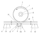
- a rail vehicle for example a wagon, of a wheel set thereof.
- the wheel 1 runs in the direction of rotation of the arrow 4 on a rail 5, which in turn is supported by a plurality of sleepers 6.
- Each wheelset bearing 3 is associated with an IR receiving unit 7, which is located in a closable housing 8.
- the housing 8 is in turn at least partially inserted into a recess 9 of a designed as a measuring or hollow threshold threshold 6a.
- the housing 8 is supported for example via four attenuators 10, of which only two attenuators 10 can be seen in the drawing, on the top of the threshold 6a.
- Attenuators 10 are made of elastically adjusted rubber or plastic or are formed by steel springs and have a stroke of about 2 to 4 mm. These attenuators 10 have the task to preclude that the inevitably occurring during the crossing of a car on the threshold 6a vibrations in a disturbing manner via the housing 8 to the therein and sensitive to vibration components, in particular to the housing 8 located in the IR Receive receiving unit 7 and bring here adverse consequences. These consequences may be that the IR receiving unit 7 occasionally fails for a shorter or longer period of time or is destroyed and / or supplies incorrect or incorrect measurement results to an evaluation unit, not shown. It may now occur in practice that one or more attenuators 10 is defective or defective. Such a defect may already be present prior to installation, during installation or occur at a later date.
- a per se known acceleration sensor 11 is arranged in the illustrated embodiment in the housing 8, which is also connected to the aforementioned evaluation unit.
- this acceleration sensor 11 the attenuation of the housing 8 and thus also the vibration impinging on the IR receiving unit 7 can be measured and compared with a previously defined and stored limit value. If the stored limit values are exceeded, a signal is sent as a maintenance alarm to a monitoring center.
- the IR receiving unit 7 and the acceleration sensor 11 are not constantly turned on and thus active.
- the IR receiving unit 7 and the acceleration sensor 11 are activated or deactivated by rail contacts 12, 13, which, viewed in the direction of travel of a train, are arranged at a distance in front of and behind the threshold 6a on a different threshold 6.
- the acceleration sensor 11 may also be arranged on the outside of the housing 8.
Landscapes
- Engineering & Computer Science (AREA)
- Mechanical Engineering (AREA)
- Automation & Control Theory (AREA)
- Measurement Of Mechanical Vibrations Or Ultrasonic Waves (AREA)
- Radiation Pyrometers (AREA)
- Testing Of Devices, Machine Parts, Or Other Structures Thereof (AREA)
- Machines For Laying And Maintaining Railways (AREA)
- Rolling Contact Bearings (AREA)
- Instruments For Viewing The Inside Of Hollow Bodies (AREA)
Abstract
Description
- Die Erfindung bezieht sich auf eine Vorrichtung zur Überwachung der Temperatur der Radsatzlager von vorbeifahrenden Schienenfahrzeugen, bestehend aus mindestens einer unterhalb des Schienenstranges in einem Gehäuse befindlichen und an eine Auswerteinheit angeschlossene IR-Empfangseinheit, wobei das Gehäuse sich über mindestens zwei Dämpfungsglieder abstützend in eine Schwelle eingesetzt ist.
- Es ist bekannt, die Temperatur von Radsatzlagern an Schienenfahrzeugen, insbesondere an Eisenbahnfahrzeugen, zu überwachen, um sogenannte Heißläufer-Entgleisungen zu vermeiden. Dazu werden von den Bahnverwaltungen IR-Messsysteme mit mindestens einer IR-Empfangseinheit eingesetzt, die sich unterhalb des Schienenstranges befindet und meist in einer besonders ausgebildeten Messschwelle oder einer Hohlschwelle untergebracht ist. Meistens sind jedoch in einer solchen Schwelle vier IR-Empfangseinheiten vorgesehen, über die die Temperaturen aller Radsatzlager eines Radsatzes erfasst werden können. Die dabei ermittelten Werte werden normalerweise mit den Werten bzw. Infrarotsignalmustern verglichen, die in einer Auswerteinheit, beispielsweise einem Rechner, abgespeichert sind. Bei unzulässigen Abweichungen wird ein Alarmsignal abgegeben. Um diese IR-Empfangseinheiten gegen äußere Einflüsse zu schützen, sind dieselben jeweils in verschließbaren Gehäusen untergebracht, die in die Mess- bzw. Hohlschwelle eingesetzt sind.
- Diese Gehäuse werden allerdings nicht direkt, sondern über jeweils mindestens zwei Dämpfungsglieder mit der Mess- bzw. Hohlschwelle verbunden, die aus Gummi, Kunststoff bestehen können oder durch Stahlfedern gebildet sind und einen Hub von etwa 2 bis 4 mm aufweisen. Dadurch wird vermieden, dass die Schwingungen, die immer beim Überfahren eines Radsatzes über die Mess- bzw. Hohlschwelle entstehen, nicht bzw. nur in geringem Maße auf die IR-Empfangseinheiten übertragen werden, die empfindliche Bauteile sind und die durch diese Schwingungen beschädigt oder zerstört werden können.
- Derzeit werden die IR-Empfangseinheiten etwa alle 6 Monate auf ihre richtige Funktionsweise überprüft. Im Hinblick auf defekte Schwingungsdämpfer kann dieser Zeitraum eindeutig zu lang sein. Defekte an den Schwingungsdämpfern können bereits vor dem Einbau vorhanden sein oder aber auch schon beim Einbau oder zu einem späteren Zeitpunkt auftreten. Ein fehlerhafter Schwingungsdämpfer bringt jedoch die Gefahr mit sich, dass die zugeordnete IR-Empfangseinheit gelegentlich über einen kürzeren oder längeren Zeitraum ausfällt, ohne dass die eigentliche Ursache erkannt werden kann. Dies kann dann zu einer Beschädigung oder Zerstörung der IR-Empfangseinheit und/oder zu fehlerhaften Messergebnissen führen.
- Der Erfindung liegt deshalb die Aufgabe zugrunde, eine Vorrichtung zur Überwachung der Temperatur der Radsatzlager von vorbeifahrenden Schienenfahrzeugen so auszugestalten, dass ein defekter bzw. nicht einwandfrei arbeitender Schwingungsdämpfer sofort erkannt werden kann und somit eine Beschädigung oder Zerstörung der IR-Empfangseinheit ausgeschlossen und daraus resultierende fehlerhafte Messergebnisse vermieden werden.
- Zur Lösung dieser Aufgabe wird gemäß der Erfindung bei einer Vorrichtung zur Überwachung der Temperatur der Radsatzlager von vorbeifahrenden Schienenfahrzeugen der eingangs genannten Art vorgeschlagen, dass dem Gehäuse ein ebenfalls an die Auswerteinheit angeschlossener Beschleunigungssensor zugeordnet ist.
- Durch den zusätzlichen, dem Gehäuse zugeordneten Beschleunigungssensors ist es möglich, fehlerhafte Schwingungsdämpfer sofort zu erkennen, indem die gemessenen Beschleunigungswerte mit den in der Auswerteinheit gespeicherten Werten verglichen und unzulässige Abweichungen sofort als Alarmsignal einer Überwachungszentrale mitgeteilt werden.
- Der Beschleunigungssensor kann dabei entweder im Gehäuse oder am Gehäuse angeordnet sein.
- Die Erfindung wird nachfolgend anhand eines in einer Zeichnung dargestellten Ausführungsbeispieles näher erläutert.
- In dieser Zeichnung ist von einem Schienenfahrzeug, beispielsweise einem Waggon, von einem Radsatz desselben nur ein Rad 1 mit einer Achse 2 und einem Radsatzlager 3 dargestellt. Das Rad 1 läuft in Drehrichtung des Pfeiles 4 auf einer Schiene 5, die ihrerseits von einer Vielzahl von Schwellen 6 getragen wird. Jedem Radsatzlager 3 ist eine IR-Empfangseinheit 7 zugeordnet, die sich in einem verschließbaren Gehäuse 8 befindet. Das Gehäuse 8 ist seinerseits zumindest teilweise in eine Ausnehmung 9 einer als Mess- oder Hohlschwelle ausgebildeten Schwelle 6a eingesetzt. Dabei stützt sich das Gehäuse 8 beispielsweise über vier Dämpfungsglieder 10, von denen in der Zeichnung nur zwei Dämpfungsglieder 10 zu sehen sind, auf der Oberseite der Schwelle 6a ab.
- Diese Dämpfungsglieder 10 bestehen aus elastisch eingestelltem Gummi oder Kunststoff oder sind durch Stahlfedern gebildet und haben einen Hub von etwa 2 bis 4 mm. Diese Dämpfungsglieder 10 haben dabei die Aufgabe, auszuschließen, dass die bei der Überfahrt eines Waggons über die Schwelle 6a zwangsläufig auftretenden Schwingungen in störender Weise über das Gehäuse 8 an die darin befindlichen und für Schwingungen empfindlichen Bauteile, insbesondere an die im Gehäuse 8 befindliche IR-Empfangseinheit 7 gelangen und hier nachteilige Folgen mit sich bringen. Diese Folgen können darin, bestehen, dass die IR-Empfangseinheit 7 gelegentlich über einen kürzeren oder längeren Zeitraum ausfällt, beschädigt oder zerstört wird und/oder falsche bzw. fehlerhafte Messergebnisse an eine nicht dargestellte Auswerteinheit liefert. Es kann nun in der Praxis vorkommen, dass ein oder mehrere Dämpfungsglieder 10 defekt ist bzw. defekt sind. Ein solcher Defekt kann bereits vor dem Einbau vorhanden sein, beim Einbau entstehen oder zu einem späteren Zeitpunkt auftreten. Um einen solchen Defekt feststellen zu können, ist im gezeichneten Ausführungsbeispiel im Gehäuse 8 ein an sich bekannter Beschleunigungssensor 11 angeordnet, der ebenfalls an die bereits erwähnte Auswerteinheit angeschlossen ist. Mittels dieses Beschleunigungssensors 11 kann die Dämpfung des Gehäuses 8 und damit auch die auf die IR-Empfangseinheit 7 auftreffende Schwingung gemessen und mit einem zuvor festgelegten und gespeicherten Grenzwert verglichen werden. Bei einer Überschreitung der gespeicherten Grenzwerte wird ein Signal als Wartungsalarm ein eine Überwachungszentrale gesandt.
- Es wird darauf hingewiesen, dass die IR-Empfangseinheit 7 und der Beschleunigungssensor 11 nicht ständig angeschaltet und damit aktiv sind. Die IR-Empfangseinheit 7 und der Beschleunigungssensor 11 werden durch Schienenkontakte 12, 13 aktiviert bzw. deaktiviert, die, in Fahrtrichtung eines Zuges gesehen, mit Abstand vor und hinter der Schwelle 6a auf einer anderen Schwelle 6 angeordnet sind.
- In Abänderung des erläuterten Ausführungsbeispieles kann der Beschleunigungssensor 11 auch außen am Gehäuse 8 angeordnet sein.
Claims (3)
- Vorrichtung zur Überwachung der Temperatur der Radsatzlager von vorbeifahrenden Schienenfahrzeugen, bestehend aus mindestens einer unterhalb des Schienenstranges in einem Gehäuse befindlichen und an eine Auswerteinheit angeschlossene IR-Empfangseinheit, wobei das Gehäuse sich über mindestens zwei Dämpfungsglieder abstützend in eine Schwelle eingesetzt ist,
dadurch gekennzeichnet,
dass dem Gehäuse (8) ein ebenfalls an die Auswerteinheit angeschlossener Beschleunigungssensor (11) zugeordnet ist. - Vorrichtung nach Anspruch 1
dadurch gekennzeichnet,
dass der Beschleunigungssensor (11) im Gehäuse (8) angeordnet ist. - Vorrichtung nach Anspruch 1
dadurch gekennzeichnet,
dass der Beschleunigungssensor (11) außen am Gehäuse (8) angeordnet ist.
Applications Claiming Priority (1)
| Application Number | Priority Date | Filing Date | Title |
|---|---|---|---|
| DE202005015790U DE202005015790U1 (de) | 2005-10-07 | 2005-10-07 | Temperatur-Überwachungsvorrichtung für Radsatzlager |
Publications (4)
| Publication Number | Publication Date |
|---|---|
| EP1772342A2 true EP1772342A2 (de) | 2007-04-11 |
| EP1772342A3 EP1772342A3 (de) | 2007-10-10 |
| EP1772342B1 EP1772342B1 (de) | 2008-12-17 |
| EP1772342B2 EP1772342B2 (de) | 2016-05-25 |
Family
ID=35530590
Family Applications (1)
| Application Number | Title | Priority Date | Filing Date |
|---|---|---|---|
| EP06020661.2A Active EP1772342B2 (de) | 2005-10-07 | 2006-09-30 | Temperatur-Überwachungsvorrichtung für Radsatzlager |
Country Status (4)
| Country | Link |
|---|---|
| EP (1) | EP1772342B2 (de) |
| AT (1) | ATE417772T1 (de) |
| DE (2) | DE202005015790U1 (de) |
| ES (1) | ES2318641T5 (de) |
Cited By (5)
| Publication number | Priority date | Publication date | Assignee | Title |
|---|---|---|---|---|
| DE102010009754A1 (de) | 2010-03-01 | 2011-09-01 | Schenck Process Gmbh | Schwelle zur Auflage von Schienen |
| EP2647543A1 (de) | 2012-04-04 | 2013-10-09 | SST Signal uns System Technik GmbH | System zur Erfassung von Eigenschaften vorbeifahrender Schienenfahrzeuge |
| DE102017120071A1 (de) * | 2017-08-31 | 2019-02-28 | Pcm Rail.One Ag | Betonschwelle für einen Eisenbahnfahrweg und Verfahren zum Erfassen von Lasten und/oder Verformungen |
| EP3984855A3 (de) * | 2020-10-16 | 2022-07-06 | Ben-Innova Systemtechnik GmbH | Vorrichtung und system zur festbrems- und/oder heissläuferortung bei schienenfahrzeugen sowie verfahren zur überwachung von rädern, radsatzlagern und/oder bremssystemen bei schienenfahrzeugen |
| EP4506229A1 (de) * | 2023-08-08 | 2025-02-12 | Alom B.V. | Eisenbahnschwelle, anordnung einer eisenbahnschwelle und einer balise sowie verfahren zur herstellung einer eisenbahnschwelle |
Families Citing this family (2)
| Publication number | Priority date | Publication date | Assignee | Title |
|---|---|---|---|---|
| DE202007006904U1 (de) | 2007-05-14 | 2007-07-19 | Neuroth, Bernd, Colmenar Viejo | Überwachungsvorrichtung für die Radsätze von Schienenfahrzeuge |
| DE102009018036B4 (de) | 2009-04-18 | 2014-02-06 | Iakov Fridman | Vorrichtung zur Vorbeugung von Zugkatastrophen aufgrund beschädigter Eisenbahnwagenradsätze sowie Verwendung dieser Vorrichtung |
Family Cites Families (3)
| Publication number | Priority date | Publication date | Assignee | Title |
|---|---|---|---|---|
| US4379330A (en) * | 1981-01-14 | 1983-04-05 | Servo Corporation Of America | Railroad car wheel detector |
| DE10122183B4 (de) * | 2001-05-08 | 2004-02-26 | Rolf Käufer | Unfall-/Brandschutz bei Fahrzeugen |
| US20040075570A1 (en) * | 2002-10-18 | 2004-04-22 | General Electric Company | Remote detection of railroad wheel and bearing temperature apparatus and method |
-
2005
- 2005-10-07 DE DE202005015790U patent/DE202005015790U1/de not_active Expired - Lifetime
-
2006
- 2006-09-30 DE DE502006002365T patent/DE502006002365D1/de active Active
- 2006-09-30 EP EP06020661.2A patent/EP1772342B2/de active Active
- 2006-09-30 AT AT06020661T patent/ATE417772T1/de not_active IP Right Cessation
- 2006-09-30 ES ES06020661.2T patent/ES2318641T5/es active Active
Cited By (9)
| Publication number | Priority date | Publication date | Assignee | Title |
|---|---|---|---|---|
| DE102010009754A1 (de) | 2010-03-01 | 2011-09-01 | Schenck Process Gmbh | Schwelle zur Auflage von Schienen |
| WO2011107231A1 (de) | 2010-03-01 | 2011-09-09 | Schenck Process Gmbh | Schwelle zur auflage von schienen |
| US8827174B2 (en) | 2010-03-01 | 2014-09-09 | Schenck Process Gmbh | Sleeper for supporting rails |
| EP2647543A1 (de) | 2012-04-04 | 2013-10-09 | SST Signal uns System Technik GmbH | System zur Erfassung von Eigenschaften vorbeifahrender Schienenfahrzeuge |
| DE102012006844A1 (de) | 2012-04-04 | 2013-10-10 | Sst Signal & System Technik Gmbh | System zur Erfassung von Eigenschaften vorbeifahrender Schienenfahrzeuge |
| DE102017120071A1 (de) * | 2017-08-31 | 2019-02-28 | Pcm Rail.One Ag | Betonschwelle für einen Eisenbahnfahrweg und Verfahren zum Erfassen von Lasten und/oder Verformungen |
| EP3984855A3 (de) * | 2020-10-16 | 2022-07-06 | Ben-Innova Systemtechnik GmbH | Vorrichtung und system zur festbrems- und/oder heissläuferortung bei schienenfahrzeugen sowie verfahren zur überwachung von rädern, radsatzlagern und/oder bremssystemen bei schienenfahrzeugen |
| EP3984855B1 (de) | 2020-10-16 | 2024-12-04 | Ben-Innova Systemtechnik GmbH | System mit einer vorrichtung zur festbrems- und/oder heissläuferortung bei schienenfahrzeugen sowie verfahren zur überwachung eines solchen systems |
| EP4506229A1 (de) * | 2023-08-08 | 2025-02-12 | Alom B.V. | Eisenbahnschwelle, anordnung einer eisenbahnschwelle und einer balise sowie verfahren zur herstellung einer eisenbahnschwelle |
Also Published As
| Publication number | Publication date |
|---|---|
| EP1772342B1 (de) | 2008-12-17 |
| ES2318641T5 (es) | 2016-10-31 |
| DE502006002365D1 (de) | 2009-01-29 |
| EP1772342B2 (de) | 2016-05-25 |
| ATE417772T1 (de) | 2009-01-15 |
| ES2318641T3 (es) | 2009-05-01 |
| EP1772342A3 (de) | 2007-10-10 |
| DE202005015790U1 (de) | 2005-12-29 |
Similar Documents
| Publication | Publication Date | Title |
|---|---|---|
| DE69920916T2 (de) | Verfahren und vorrichtung zur ermittlung defekter eisenbahnräder | |
| DE102007024065B3 (de) | Vorrichtung und Verfahren zur Fehlerüberwachung von Fahrwerkskomponenten von Schienenfahrzeugen | |
| EP2697521B1 (de) | Vorrichtung zum erkennen von relativbewegungen in einem fahrzeug | |
| DE102009018036B4 (de) | Vorrichtung zur Vorbeugung von Zugkatastrophen aufgrund beschädigter Eisenbahnwagenradsätze sowie Verwendung dieser Vorrichtung | |
| EP3445635A1 (de) | Verfahren zum betreiben einer ortungseinrichtung sowie ortungseinrichtung | |
| EP1772342B1 (de) | Temperatur-Überwachungsvorrichtung für Radsatzlager | |
| EP3310637A1 (de) | Prüfeinrichtung und verfahren zur überprüfung eines definierten profils von einem zugverband aus fahrzeugen, insbesondere schienenfahrzeugen | |
| EP3464000B1 (de) | Verfahren sowie vorrichtung zum automatischen prüfen von bremsen eines spurgebundenen fahrzeugs | |
| EP1839990A2 (de) | Anordnung zur Überprüfung der Laufräder von Schienenfahrzeugen | |
| DE10145433C2 (de) | Verfahren und Vorrichtung zur Fehlerüberwachung von Komponenten von Schienenfahrzeugen | |
| EP1904356A2 (de) | Verfahren und vorrichtung zur erfassung der entgleisungsgefahr von schienenfahrzeugen | |
| EP2647543B1 (de) | System zur Erfassung von Eigenschaften vorbeifahrender Schienenfahrzeuge | |
| DE202005005278U1 (de) | Vorrichtung zur Überwachung der Radsatzlagertemperatur an Schienenfahrzeugen zur Vermeidung von Heißläufer-Entgleisungen | |
| DE19827931C1 (de) | Sensorüberwachungssystem für mehrachsige Fahrzeuge | |
| EP1165355B1 (de) | Verfahren und einrichtung zum überwachen eines fahrzeuges | |
| DE10062602A1 (de) | Verfahren und Vorrichtung zum Überwachen des Fahrverhaltens von Schienenfahrzeugen und zur Diagnose von Komponenten von Schienenfahrzeugen | |
| DE4432329A1 (de) | Verfahren zur Zuglauf- und Fahrwegüberwachung | |
| DE102008008578B3 (de) | Ermittlung der dynamischen Radkraft eines Eisenbahnfahrzeugs auf das Herzstück einer Weiche | |
| DE202007006904U1 (de) | Überwachungsvorrichtung für die Radsätze von Schienenfahrzeuge | |
| DE102009015011A1 (de) | Verfahren zur Überwachung der Laufstabilität bei Schienenfahrzeugen | |
| AT519579A4 (de) | Vorrichtung zum Messen von Radaufstandskräften eines Schienenfahrzeugs | |
| AT410924B (de) | Verfahren und vorrichtung zur erkennung eines schlingerdämpferschadens eines schienenfahrzeuges | |
| DE102006001221A1 (de) | Verfahren zur Überwachung insbesondere des Profils von Rädern eines Schienenfahrzeugs | |
| DE10009708C1 (de) | Verfahren und Vorrichtung zum Ermitteln der Eigenschaften der Drehdämpfung eines Drehgestells von Schienenfahrzeugen | |
| WO2014063921A1 (de) | Verfahren und vorrichtung zur schienenbrucherkennung |
Legal Events
| Date | Code | Title | Description |
|---|---|---|---|
| PUAI | Public reference made under article 153(3) epc to a published international application that has entered the european phase |
Free format text: ORIGINAL CODE: 0009012 |
|
| AK | Designated contracting states |
Kind code of ref document: A2 Designated state(s): AT BE BG CH CY CZ DE DK EE ES FI FR GB GR HU IE IS IT LI LT LU LV MC NL PL PT RO SE SI SK TR |
|
| AX | Request for extension of the european patent |
Extension state: AL BA HR MK YU |
|
| PUAL | Search report despatched |
Free format text: ORIGINAL CODE: 0009013 |
|
| AK | Designated contracting states |
Kind code of ref document: A3 Designated state(s): AT BE BG CH CY CZ DE DK EE ES FI FR GB GR HU IE IS IT LI LT LU LV MC NL PL PT RO SE SI SK TR |
|
| AX | Request for extension of the european patent |
Extension state: AL BA HR MK YU |
|
| RIC1 | Information provided on ipc code assigned before grant |
Ipc: B61L 1/20 20060101AFI20070831BHEP Ipc: B61K 9/04 20060101ALI20061219BHEP |
|
| 17P | Request for examination filed |
Effective date: 20080121 |
|
| AKX | Designation fees paid |
Designated state(s): AT BE BG CH CY CZ DE DK EE ES FI FR GB GR HU IE IS IT LI LT LU LV MC NL PL PT RO SE SI SK TR |
|
| GRAP | Despatch of communication of intention to grant a patent |
Free format text: ORIGINAL CODE: EPIDOSNIGR1 |
|
| GRAS | Grant fee paid |
Free format text: ORIGINAL CODE: EPIDOSNIGR3 |
|
| GRAS | Grant fee paid |
Free format text: ORIGINAL CODE: EPIDOSNIGR3 |
|
| GRAA | (expected) grant |
Free format text: ORIGINAL CODE: 0009210 |
|
| AK | Designated contracting states |
Kind code of ref document: B1 Designated state(s): AT BE BG CH CY CZ DE DK EE ES FI FR GB GR HU IE IS IT LI LT LU LV MC NL PL PT RO SE SI SK TR |
|
| REG | Reference to a national code |
Ref country code: GB Ref legal event code: FG4D Free format text: NOT ENGLISH |
|
| REG | Reference to a national code |
Ref country code: CH Ref legal event code: EP |
|
| REG | Reference to a national code |
Ref country code: IE Ref legal event code: FG4D Free format text: LANGUAGE OF EP DOCUMENT: GERMAN |
|
| REF | Corresponds to: |
Ref document number: 502006002365 Country of ref document: DE Date of ref document: 20090129 Kind code of ref document: P |
|
| PG25 | Lapsed in a contracting state [announced via postgrant information from national office to epo] |
Ref country code: LT Free format text: LAPSE BECAUSE OF FAILURE TO SUBMIT A TRANSLATION OF THE DESCRIPTION OR TO PAY THE FEE WITHIN THE PRESCRIBED TIME-LIMIT Effective date: 20081217 |
|
| REG | Reference to a national code |
Ref country code: ES Ref legal event code: FG2A Ref document number: 2318641 Country of ref document: ES Kind code of ref document: T3 |
|
| PG25 | Lapsed in a contracting state [announced via postgrant information from national office to epo] |
Ref country code: FI Free format text: LAPSE BECAUSE OF FAILURE TO SUBMIT A TRANSLATION OF THE DESCRIPTION OR TO PAY THE FEE WITHIN THE PRESCRIBED TIME-LIMIT Effective date: 20081217 Ref country code: NL Free format text: LAPSE BECAUSE OF FAILURE TO SUBMIT A TRANSLATION OF THE DESCRIPTION OR TO PAY THE FEE WITHIN THE PRESCRIBED TIME-LIMIT Effective date: 20081217 Ref country code: SI Free format text: LAPSE BECAUSE OF FAILURE TO SUBMIT A TRANSLATION OF THE DESCRIPTION OR TO PAY THE FEE WITHIN THE PRESCRIBED TIME-LIMIT Effective date: 20081217 Ref country code: LV Free format text: LAPSE BECAUSE OF FAILURE TO SUBMIT A TRANSLATION OF THE DESCRIPTION OR TO PAY THE FEE WITHIN THE PRESCRIBED TIME-LIMIT Effective date: 20081217 Ref country code: PL Free format text: LAPSE BECAUSE OF FAILURE TO SUBMIT A TRANSLATION OF THE DESCRIPTION OR TO PAY THE FEE WITHIN THE PRESCRIBED TIME-LIMIT Effective date: 20081217 |
|
| NLV1 | Nl: lapsed or annulled due to failure to fulfill the requirements of art. 29p and 29m of the patents act | ||
| REG | Reference to a national code |
Ref country code: IE Ref legal event code: FD4D |
|
| PG25 | Lapsed in a contracting state [announced via postgrant information from national office to epo] |
Ref country code: EE Free format text: LAPSE BECAUSE OF FAILURE TO SUBMIT A TRANSLATION OF THE DESCRIPTION OR TO PAY THE FEE WITHIN THE PRESCRIBED TIME-LIMIT Effective date: 20081217 Ref country code: RO Free format text: LAPSE BECAUSE OF FAILURE TO SUBMIT A TRANSLATION OF THE DESCRIPTION OR TO PAY THE FEE WITHIN THE PRESCRIBED TIME-LIMIT Effective date: 20081217 Ref country code: BG Free format text: LAPSE BECAUSE OF FAILURE TO SUBMIT A TRANSLATION OF THE DESCRIPTION OR TO PAY THE FEE WITHIN THE PRESCRIBED TIME-LIMIT Effective date: 20090317 Ref country code: IE Free format text: LAPSE BECAUSE OF FAILURE TO SUBMIT A TRANSLATION OF THE DESCRIPTION OR TO PAY THE FEE WITHIN THE PRESCRIBED TIME-LIMIT Effective date: 20081217 |
|
| PG25 | Lapsed in a contracting state [announced via postgrant information from national office to epo] |
Ref country code: SE Free format text: LAPSE BECAUSE OF FAILURE TO SUBMIT A TRANSLATION OF THE DESCRIPTION OR TO PAY THE FEE WITHIN THE PRESCRIBED TIME-LIMIT Effective date: 20090317 Ref country code: PT Free format text: LAPSE BECAUSE OF FAILURE TO SUBMIT A TRANSLATION OF THE DESCRIPTION OR TO PAY THE FEE WITHIN THE PRESCRIBED TIME-LIMIT Effective date: 20090518 Ref country code: CZ Free format text: LAPSE BECAUSE OF FAILURE TO SUBMIT A TRANSLATION OF THE DESCRIPTION OR TO PAY THE FEE WITHIN THE PRESCRIBED TIME-LIMIT Effective date: 20081217 Ref country code: IS Free format text: LAPSE BECAUSE OF FAILURE TO SUBMIT A TRANSLATION OF THE DESCRIPTION OR TO PAY THE FEE WITHIN THE PRESCRIBED TIME-LIMIT Effective date: 20090417 |
|
| PLBI | Opposition filed |
Free format text: ORIGINAL CODE: 0009260 |
|
| PG25 | Lapsed in a contracting state [announced via postgrant information from national office to epo] |
Ref country code: SK Free format text: LAPSE BECAUSE OF FAILURE TO SUBMIT A TRANSLATION OF THE DESCRIPTION OR TO PAY THE FEE WITHIN THE PRESCRIBED TIME-LIMIT Effective date: 20081217 |
|
| PLAX | Notice of opposition and request to file observation + time limit sent |
Free format text: ORIGINAL CODE: EPIDOSNOBS2 |
|
| 26 | Opposition filed |
Opponent name: SST SIGNAL & SYSTEM TECHNICK GMBH Effective date: 20090916 |
|
| PG25 | Lapsed in a contracting state [announced via postgrant information from national office to epo] |
Ref country code: DK Free format text: LAPSE BECAUSE OF FAILURE TO SUBMIT A TRANSLATION OF THE DESCRIPTION OR TO PAY THE FEE WITHIN THE PRESCRIBED TIME-LIMIT Effective date: 20081217 |
|
| PLBB | Reply of patent proprietor to notice(s) of opposition received |
Free format text: ORIGINAL CODE: EPIDOSNOBS3 |
|
| BERE | Be: lapsed |
Owner name: NEUROTH, BERND Effective date: 20090930 |
|
| PG25 | Lapsed in a contracting state [announced via postgrant information from national office to epo] |
Ref country code: MC Free format text: LAPSE BECAUSE OF NON-PAYMENT OF DUE FEES Effective date: 20090930 |
|
| REG | Reference to a national code |
Ref country code: FR Ref legal event code: ST Effective date: 20100531 |
|
| PG25 | Lapsed in a contracting state [announced via postgrant information from national office to epo] |
Ref country code: FR Free format text: LAPSE BECAUSE OF NON-PAYMENT OF DUE FEES Effective date: 20090930 |
|
| PG25 | Lapsed in a contracting state [announced via postgrant information from national office to epo] |
Ref country code: BE Free format text: LAPSE BECAUSE OF NON-PAYMENT OF DUE FEES Effective date: 20090930 |
|
| PG25 | Lapsed in a contracting state [announced via postgrant information from national office to epo] |
Ref country code: GR Free format text: LAPSE BECAUSE OF FAILURE TO SUBMIT A TRANSLATION OF THE DESCRIPTION OR TO PAY THE FEE WITHIN THE PRESCRIBED TIME-LIMIT Effective date: 20090318 |
|
| PG25 | Lapsed in a contracting state [announced via postgrant information from national office to epo] |
Ref country code: AT Free format text: LAPSE BECAUSE OF NON-PAYMENT OF DUE FEES Effective date: 20090930 |
|
| PG25 | Lapsed in a contracting state [announced via postgrant information from national office to epo] |
Ref country code: LU Free format text: LAPSE BECAUSE OF NON-PAYMENT OF DUE FEES Effective date: 20090930 |
|
| REG | Reference to a national code |
Ref country code: CH Ref legal event code: PL |
|
| PLCK | Communication despatched that opposition was rejected |
Free format text: ORIGINAL CODE: EPIDOSNREJ1 |
|
| GBPC | Gb: european patent ceased through non-payment of renewal fee |
Effective date: 20100930 |
|
| PG25 | Lapsed in a contracting state [announced via postgrant information from national office to epo] |
Ref country code: HU Free format text: LAPSE BECAUSE OF FAILURE TO SUBMIT A TRANSLATION OF THE DESCRIPTION OR TO PAY THE FEE WITHIN THE PRESCRIBED TIME-LIMIT Effective date: 20090618 |
|
| APBM | Appeal reference recorded |
Free format text: ORIGINAL CODE: EPIDOSNREFNO |
|
| APBP | Date of receipt of notice of appeal recorded |
Free format text: ORIGINAL CODE: EPIDOSNNOA2O |
|
| APAH | Appeal reference modified |
Free format text: ORIGINAL CODE: EPIDOSCREFNO |
|
| PG25 | Lapsed in a contracting state [announced via postgrant information from national office to epo] |
Ref country code: LI Free format text: LAPSE BECAUSE OF NON-PAYMENT OF DUE FEES Effective date: 20100930 Ref country code: CH Free format text: LAPSE BECAUSE OF NON-PAYMENT OF DUE FEES Effective date: 20100930 |
|
| PG25 | Lapsed in a contracting state [announced via postgrant information from national office to epo] |
Ref country code: GB Free format text: LAPSE BECAUSE OF NON-PAYMENT OF DUE FEES Effective date: 20100930 Ref country code: TR Free format text: LAPSE BECAUSE OF FAILURE TO SUBMIT A TRANSLATION OF THE DESCRIPTION OR TO PAY THE FEE WITHIN THE PRESCRIBED TIME-LIMIT Effective date: 20081217 |
|
| PG25 | Lapsed in a contracting state [announced via postgrant information from national office to epo] |
Ref country code: CY Free format text: LAPSE BECAUSE OF FAILURE TO SUBMIT A TRANSLATION OF THE DESCRIPTION OR TO PAY THE FEE WITHIN THE PRESCRIBED TIME-LIMIT Effective date: 20081217 |
|
| APBQ | Date of receipt of statement of grounds of appeal recorded |
Free format text: ORIGINAL CODE: EPIDOSNNOA3O |
|
| RAP2 | Party data changed (patent owner data changed or rights of a patent transferred) |
Owner name: NEUROTH, BERND |
|
| RIN2 | Information on inventor provided after grant (corrected) |
Inventor name: NEUROTH, BERND |
|
| APBU | Appeal procedure closed |
Free format text: ORIGINAL CODE: EPIDOSNNOA9O |
|
| PUAH | Patent maintained in amended form |
Free format text: ORIGINAL CODE: 0009272 |
|
| STAA | Information on the status of an ep patent application or granted ep patent |
Free format text: STATUS: PATENT MAINTAINED AS AMENDED |
|
| 27A | Patent maintained in amended form |
Effective date: 20160525 |
|
| AK | Designated contracting states |
Kind code of ref document: B2 Designated state(s): AT BE BG CH CY CZ DE DK EE ES FI FR GB GR HU IE IS IT LI LT LU LV MC NL PL PT RO SE SI SK TR |
|
| REG | Reference to a national code |
Ref country code: DE Ref legal event code: R102 Ref document number: 502006002365 Country of ref document: DE |
|
| REG | Reference to a national code |
Ref country code: ES Ref legal event code: DC2A Ref document number: 2318641 Country of ref document: ES Kind code of ref document: T5 Effective date: 20161031 |
|
| P01 | Opt-out of the competence of the unified patent court (upc) registered |
Effective date: 20230601 |
|
| REG | Reference to a national code |
Ref country code: DE Ref legal event code: R082 Ref document number: 502006002365 Country of ref document: DE Representative=s name: KBN IP PATENTANWAELTE PARTNERSCHAFT MBB, DE |
|
| PGFP | Annual fee paid to national office [announced via postgrant information from national office to epo] |
Ref country code: DE Payment date: 20250919 Year of fee payment: 20 |
|
| PGFP | Annual fee paid to national office [announced via postgrant information from national office to epo] |
Ref country code: IT Payment date: 20250930 Year of fee payment: 20 |
|
| PGFP | Annual fee paid to national office [announced via postgrant information from national office to epo] |
Ref country code: ES Payment date: 20251020 Year of fee payment: 20 |