EP1776484B1 - Vorrichtung zur herstellung von kompaktiertem eisen aus reduzierten materialien, die feines direkt reduziertes eisen umfassen, und vorrichtung zur herstellung von schmelzflüssigem eisen - Google Patents
Vorrichtung zur herstellung von kompaktiertem eisen aus reduzierten materialien, die feines direkt reduziertes eisen umfassen, und vorrichtung zur herstellung von schmelzflüssigem eisen Download PDFInfo
- Publication number
- EP1776484B1 EP1776484B1 EP05756726A EP05756726A EP1776484B1 EP 1776484 B1 EP1776484 B1 EP 1776484B1 EP 05756726 A EP05756726 A EP 05756726A EP 05756726 A EP05756726 A EP 05756726A EP 1776484 B1 EP1776484 B1 EP 1776484B1
- Authority
- EP
- European Patent Office
- Prior art keywords
- irons
- cheek plates
- rolls
- couple
- pressing
- Prior art date
- Legal status (The legal status is an assumption and is not a legal conclusion. Google has not performed a legal analysis and makes no representation as to the accuracy of the status listed.)
- Expired - Lifetime
Links
Images


Classifications
-
- C—CHEMISTRY; METALLURGY
- C22—METALLURGY; FERROUS OR NON-FERROUS ALLOYS; TREATMENT OF ALLOYS OR NON-FERROUS METALS
- C22B—PRODUCTION AND REFINING OF METALS; PRETREATMENT OF RAW MATERIALS
- C22B1/00—Preliminary treatment of ores or scrap
- C22B1/14—Agglomerating; Briquetting; Binding; Granulating
- C22B1/24—Binding; Briquetting ; Granulating
- C22B1/248—Binding; Briquetting ; Granulating of metal scrap or alloys
-
- B—PERFORMING OPERATIONS; TRANSPORTING
- B30—PRESSES
- B30B—PRESSES IN GENERAL
- B30B15/00—Details of, or accessories for, presses; Auxiliary measures in connection with pressing
- B30B15/30—Feeding material to presses
- B30B15/302—Feeding material in particulate or plastic state to moulding presses
- B30B15/308—Feeding material in particulate or plastic state to moulding presses in a continuous manner, e.g. for roller presses, screw extrusion presses
Definitions
- the present invention relates to an apparatus for manufacturing compacted irons and an apparatus for manufacturing molten irons using the same, and more particularly, to an apparatus for manufacturing compacted irons by compacting reduced materials comprising fine direct reduced irons and manufacturing compacted irons and an apparatus for manufacturing molten irons using the same.
- the iron and steel industry is a core industry that supplies the basic materials needed in construction and in the manufacture of automobiles, ships, home appliances, etc. Further, it is an industry which has the longest history having advanced since the dawn of human history. Iron works, which play a pivotal roll in the iron and steel industry, produce steel from molten iron, and then supply it to customers, after producing the molten iron (i.e., pig iron in a molten state) using iron ores and coals as raw materials.
- molten iron i.e., pig iron in a molten state
- blast furnace method irons ores, which have gone through a sintering process, and cokes, which are produced using bituminous coals as raw materials, are charged into a blast furnace together and oxygen is supplied to the blast furnace to reduce the iron ores to irons, thereby manufacturing molten irons.
- the blast furnace method which is the most popular in plants for manufacturing molten irons, requires that raw materials have strength of at least a predetermined level and have grain sizes that can ensure permeability in the furnace, taking into account reaction characteristics.
- US Patent No. 5,534,046 An installation for manufacturing molten irons directly using raw coals and fine iron ores is disclosed in US Patent No. 5,534,046 .
- the apparatus for manufacturing molten irons disclosed in US Patent No. 5,534,046 includes three-stage fluidized-bed reactors forming a bubbling fluidized bed therein and a melter-gasifier connected thereto.
- the fine iron ores and additives at room temperature are charged into the first fluidized-bed reactor and successively go through three-stage fluidized-bed reactors. Since hot reducing gas produced from the melter-gasifier is supplied to the three-stage fluidized-bed reactors, the temperature of the iron ores and additives is raised by contact with the hot reducing gas. Simultaneously, 90% or more of the iron ores and additives are reduced and 30% or more of them are sintered, and they are charged into the melter-gasifier.
- a coal packed bed is formed in the melter-gasifier by supplying coals thereto. Therefore, iron ores and additives are melted and slagged in the coal packed bed and then are discharged as molten irons and slags.
- the oxygen supplied from a plurality of tuyeres installed on the outer wall of the melter-gasifier burns a coal packed bed and is converted to a hot reducing gas. Then, the hot reducing gas is supplied to the fluidized-bed reactors in order to reduce iron ores and additives and is exhausted outside.
- US Patent No. 5,666,638 forming the preamble of claim 1 discloses a method for manufacturing oval-shaped briquettes made of sponge irons and an apparatus using the same.
- US Patent Nos. 4,093,455 , 4,076,520 and 4,033,559 disclose a method for manufacturing plate-shaped or corrugation-shaped briquettes made of sponge irons and an apparatus using the same.
- fine reduced irons are hot briquetted and then cooled, and thereby they are manufactured into briquettes made of sponge irons in order to suitably transport them a long distance.
- cheek plates are installed at both sides of the rolls in order to prevent the fine reduced irons from elutriating outside during manufacturing the briquettes. Since the apparatus for manufacturing briquettes is small-sized, using normal cheek plates can sufficiently prevent fine reduced irons from elutriating.
- a briquetting press comprising the material to be briquetted is charged, the charging hopper comprising guide tubes extending downward, a couple of rolls separated from each other to form a gap between the rolls, and a couple of cheek plates installed at the sides of the couple of rolls.
- the present invention has been made to solve the above-mentioned problems, and provides an apparatus for manufacturing compacted irons that is suitable for manufacturing a large amount of compacted irons.
- the present invention provides an apparatus for manufacturing molten irons provided with the apparatus for manufacturing compacted irons.
- the apparatus for manufacturing compacted irons includes a charging hopper into which reduced materials containing fine reduced irons are charged; a couple of rolls separated from each other to form a gap between the rolls; and a couple of cheek plates installed on the sides of the couple of rolls.
- the charging hopper includes guide tubes extending downward.
- the couple of rolls compact the reduced materials containing fine reduced irons discharged from the charging hopper and manufacture compacted irons.
- the couple of cheek plates prevent leakage of the reduced materials containing fine reduce irons charged into the gap and are overlapped with the guide tubes in the axis direction of the rolls.
- a side of the sealing member may be attached to the grooves and the sealing member is slanted relative to the grooves.
- the slanted surface of the sealing member directs to the outer side of the gap.
- the apparatus for manufacturing compacted irons according to the present invention may further include a feeding box for transferring the reduced materials containing fine reduced irons to the couple of rolls and in this case, the sealing member may support the feeding box.
- the sealing member may be made of a heat-resistant steel plate.
- the grooves may include a first groove formed along the arranging direction of 30 the couple of rolls and second grooves connected to both ends of the first groove.
- the second grooves may be formed along the axis direction of the couple of rolls.
- the lengths of the guide tubes become longer as the guide tubes go away from the center of the gap.
- each guide tube may be overlapped with a surface of the cheek plate.
- a slanted concave portion is formed on a surface of the cheek plate facing the couple of rolls and that the concave portion is overlapped with the guide tube.
- a stepped portion may be formed on the center of the concave portion of the cheek plate along the arranging direction of the rolls.
- the stepped portion is preferably formed on the guide tube.
- the stepped portion of the cheek plate and the stepped portion of the guide tube preferably face each other.
- the apparatus for manufacturing compacted irons according to the present invention may further include a supporter for supporting the cheek plate.
- the supporter may be attached to the cheek plate at the opposite side of the gap so that the cheek plate is located between the supporter and the gap.
- An internal space may be formed on the surface of the supporter which is adjacent to the cheek plate.
- the apparatus for manufacturing compacted irons according to the present invention may further include a device for pressing the cheek plate to the gap.
- the device for pressing the cheek plate may be bendable.
- the device for pressing the cheek plate includes a bar, of which one end is adjacent to the cheek plate, for pressing and supporting the cheek plate, and a concave portion is formed at the other end; a tension spindle combined with the concave portion of the bar, the outer surface of which has grooves shaped as a screw formed thereon; a supporting member having an opening through which the bar penetrates; a block having an opening through which the tension spindle is screwed and combined with the opening; a spring inserted into the tension spindle; and a guiding member through which the tension spindle penetrates.
- the guiding member may be combined with both sides of the supporting member.
- the device for pressing the cheek plate is preferably shaped as a bar.
- At least three devices for pressing the cheek plate are installed.
- the device for pressing the cheek plate according to the present invention may further include a frame installed in the outer side of the couple of rolls.
- the device for pressing the cheek plate may penetrate into the frame and may support the cheek plate.
- the supporting member, the block, the spring, and the guiding member may be combined with each other in order from the bar to the tension spindle.
- both ends of the guiding member are bent toward the pressing direction and that the guiding member is combined with both sides of the supporting member.
- a stepping portion may be formed on the inner surfaces of both bent ends of the guiding member in order for the block to be limited in movement.
- the center portion of the supporting member may be inserted between the bent portions of the guiding member and may be combined with the guiding member with pins.
- the guiding member may be capable of being rotated at approximately 90 degrees using the pins as an axis.
- the guiding member surrounds the block and the sides of the spring.
- the block is preferably shaped as a rectangular parallelepiped and both sides of the block preferably face an inner surface of the guiding member.
- the end portion of the supporting member may protrude toward both sides of the supporting member and may be adjacent to the guiding member.
- the apparatus for manufacturing molten irons includes the above apparatus for manufacturing compacted irons; a breaker for breaking compacted irons discharged from the apparatus for manufacturing compacted irons; and a melter-gasifier into which the compacted irons, which are broken by the breaker, are charged and are melted.
- At least one of the coals selected from the group of lumped coals and coal briquettes may be supplied to the melter-gasifier.
- Fig. 1 schematically shows an apparatus for manufacturing compacted irons 100 including a charging hopper 10 and a couple of rolls 20. Gears are attached to the ends of the rolls, and thereby the couple of rolls are interlocked and rotated together.
- the structure of the apparatus for manufacturing compacted irons shown in Fig. 1 is merely to illustrate the present invention and the present invention is not limited thereto. Therefore, the apparatus for manufacturing compacted irons can be modified in other forms.
- the reduced materials containing fine reduced irons are charged into the charging hopper 10 through the opening 16 located in the center thereof along the direction indicated by the arrow A'.
- the reduced materials containing fine reduced irons are manufactured from iron ores.
- the reduced materials containing fine reduced irons further comprise sintered additives and are reduced while going through multi-stage fluidized-bed reactors.
- the reduced materials containing fine reduced irons manufactured by using other methods can be charged into the charging hopper 10.
- Ventilation openings 14 are formed on the upper side of the charging hopper 10, thereby eliminating gas produced from the hot reduced materials containing fine reduced irons.
- the charging hopper 10 includes guide tubes 70 extending downward.
- the guide tubes 70 are inserted into the feeding box 30 located below and are combined therewith.
- the feeding box 30 closely adheres to the cheek plates 80 (shown in Fig. 2 ) which are overlapped with the guide tubes 70 along the axis direction of the rolls 20 (Y-axis direction).
- Screw feeders 12 are installed in the charging hopper 10.
- the screw feeders 12 discharge the reduced materials containing fine reduced irons charged into the charging hopper 10 to the gap between the couple of rolls 20.
- the gap means a space formed between the rolls along the longitudinal direction of the couple of rolls.
- Screws 122 shown in Fig. 2
- Screws 122 installed at a lower end of the screw feeders 12 discharge the reduced materials containing fine reduced irons collected in their lower portions due to gravity downward by rotating by a motor (not shown).
- the motor is installed in the upper end of the screw feeders 12.
- Scrapers 124 (shown in Fig. 2 ) installed on the screw feeders 12 eliminate fine reduced irons adhered to the inner walls of the charging hopper 10.
- the couple of rolls 20 are located in the roll casing 24.
- the couple of rolls 20 are separated from each other and so form a gap therebetween.
- the couple of rolls 20 compress the reduced materials containing fine reduced irons discharged by the screw feeders 12 and thereby manufacture compacted irons.
- the roll cover 26 is attached on the external side of the roll 20.
- Fig. 2 shows an internal section of the apparatus for manufacturing compacted irons shown in Fig. 1 .
- the enlarged circle of Fig. 2 shows a magnified cheek plate 80 supporting both sides of the couple of rolls 20.
- the reduced materials containing fine reduced irons are charged into the feeding box 30 by the screw feeders 12 through the guide tubes 70.
- the feeding box 30 is installed below the charging hopper 10 and transfers the reduced materials containing fine reduced irons to the couple of rolls 20.
- the feeding box 30 forms a lower space bulged to the charging hopper 10.
- the feeding box 30 has such a structure to be capable of ensuring a stagnated bed of a large amount of charged reduced materials containing fine reduced irons. Therefore, it is possible to suitably supply the reduced materials containing fine reduced irons to the center of the gap of the couple of rolls 20.
- the lengths of the guide tubes 70 become longer as the guide tubes 70 have more distance from the center of the gap. Therefore, it is possible to effectively distribute reduced materials containing fine reduced irons into the inner space of the feeding box 30, thereby smoothly manufacturing compacted irons in the center of the rolls. End portions 701 and the area around the end portions 701 of the guide tubes 70 corresponding to the longest lengths of the guide tubes 70 are overlapped with surfaces of the cheek plates 80. Therefore, the reduced materials containing fine reduced irons, which are discharged from the guide tubes 70, are not elutriated outside and are smoothly supplied to the gap formed between the rolls 20.
- the cheek plates 80 are installed at both sides of the gap formed between the rolls 20.
- the cheek plates 80 prevent the reduced materials containing fine reduce irons entering the gap from leaking outside.
- sealing member 84 Since the sealing member 84 is slanted, elutriated fine reduced irons are entrapped in the lower side of the sealing member 84 and are not elutriated outside. Therefore, the reduced materials containing fine reduced irons, which enter the feeding box 30, are not elutriated, and so it is possible to realize a stable manufacturing process.
- a stepped portion 703 is formed on each guide tube 70.
- a stepped portion 861 is formed in the center of a concave portion 86 of each cheek plate 80 along the arranging direction of the rolls 20. Since the stepped portion 703 of the guide tube 70 and the stepped portion 861 of the cheek plate 80 face each other, the fine reduced irons are prevented from elutriating through the overlapped space formed between the guide tube 70 and the cheek plate 80. Namely, obstacles made of the stepped portions, which face each other, are formed in the passageway formed between the guide tube 70 and the cheek plate 80, and thereby the fine reduced irons are prevented from elutriating outside.
- the apparatus for manufacturing compacted irons further includes a supporter 88 for supporting the cheek plates 80.
- the supporter 88 is attached to the cheek plates 80 at the opposite side of the gap, locating the cheek plate 80 therebetween.
- the supporter 88 supports the cheek plates 80.
- the upper portion of the supporter 88 is protruded toward the upper portion of the feeding box 30.
- the cheek plates 80 can be assembled through the upper opening of the feeding box 30.
- An internal space 89 is formed in the surface of the supporter 88 which is adjacent to the cheek plates 80. Therefore, the areas in which the supporter 88 is adjacent to the cheek plates 80 is minimized, thereby keeping uniform heat distribution and preventing staggering by heat transfer.
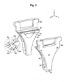
- Fig. 3 shows an exploded state of the cheek plates shown in Fig. 2 .
- the enlarged circle of Fig. 3 shows the grooves 82 formed on the upper side of the cheek plates 80 in detail.
- the couple of rolls are arranged in the X-axis direction between the couple of cheek plates 80 located in Y-axis direction.
- the supporter 88 installed outside of the cheek plates 80 presses the cheek plates 80 to the rolls 20.
- An opening 87 is formed in the outer side of the supporter 88 in order to assemble it with bolts.
- the opening 87 is manufactured as a long hole, thereby absorbing the expansion and contraction amount of the cheek plates 80 when the cheek plates 80 are thermally expanded.
- the grooves 82 are formed on an upper portion of the cheek plates 80 and the grooves closely adhere to the feeding box 30 (shown in Fig. 2 ). Sealing members 84 are attached along the grooves 82.
- the sealing members 84 can be attached by welding and also by other methods.
- each of the grooves 82 includes a first groove 822 and a couple of second grooves 824.
- the first groove 822 is formed along the arranging direction of the couple of rolls (not shown).
- the second grooves 824 are connected to both ends of the first groove 822 and are arranged along the axis direction of the couple of rolls (not shown). Since the first groove 822 and the second grooves 824 are formed surrounding the rolls and the grooves 82 are closely adhered to the feeding box 30, the fine reduced irons are essentially prevented from elutriating outside.
- the slanted sealing members 84 are installed in the grooves 82 and sides 841 thereof are attached to the grooves 82. Attachment can be accomplished by using welding and by other various methods. Especially, it is preferable that the slanted surfaces of the sealing members 84 direct to the outer sides of the gap. Therefore, the sealing members 84 support the feeding box 30 whilst closely adhering to the cheek plates 80, and thereby guiding any fine reduced irons passed outside to the lower portions of the slanted surfaces of the sealing members 84 and entrapping them therein. By using this method, an amount of the fine reduced irons that are elutriated outside is minimized.
- the sealing members 84 are located in the closely adhering surface between the cheek plates 80 and the feeding box 30 and prevent the fine reduced irons from elutriating outside, they are disposed in a hot environment. Therefore, the sealing members 84 are preferably made of a heat-resistant steel plate in order to resist the hot temperature.
- a stainless steel can be used as a heat-resistant steel plate.
- STS310S can be used.
- a stepped portion 861 and a slanted concave portion 86 are formed on a surface of each cheek plate 80 facing the couple of rolls along the arranging direction of the rolls, and are overlapped with the guide tube 70 (shown in Fig. 2 ). Therefore, it is possible to prevent the fine reduced irons charged from the guide tubes from elutriating, thereby realizing a stable manufacturing process.
- the cheek plates minimize the amount of the fine reduced irons that is elutriated outside. Therefore, it is possible that not only the cost for manufacturing reduced materials containing fine reduced irons is prevented from being raised, but also that the compacted irons are stably manufactured.
- Fig. 4 shows an internal structure of an apparatus for manufacturing compacted irons 150 according to a second embodiment of the present invention.
- the structure of the apparatus for manufacturing the compacted irons 150 according to the second embodiment of the present invention is the same as that of the apparatus for manufacturing the compacted irons 100 according to the first embodiment of the present invention, except for a device for pressing the cheek plates 90. Therefore, the same reference numerals are used to refer to the same elements.
- the device for pressing the cheek plates 90 presses the cheek plates 80 to the gap, thereby more stably fixing the cheek plates 80. Therefore, it is possible to effectively prevent the fine reduced irons from elutriating. Since the device for pressing the cheek plates 90 is bendable, it is possible to disassemble and assemble it whenever the cheek plates 80 are overhauled.
- the device for pressing the cheek plate 90 is shaped as a bar, it is possible to support a plurality of points of the cheek plates 80. At least three of the devices for pressing the cheek plates 90 are installed in order to press the cheek plates 80. Therefore, the fine reduce irons are prevented from elutriating outside. Especially, since the cheek plates 80 are shaped almost as a triangle, it is preferable that three devices for pressing the cheek plates 90 are installed in a triangle shape.
- a frame 29 protects the elements included in the apparatus for manufacturing the compacted irons 150 from outside.
- the device for pressing the cheek plates 90 penetrates the frame 29 and supports the cheek plates 80. Accordingly, even though pressure acts on the cheek plates 80, it is possible to resist the pressure by the device for pressing the cheek plates 90 supported by the frame 29.
- Fig. 5 shows an exploded view of the device for pressing the cheek plates 90 shown in Fig. 4 .
- the structure of the device for pressing the cheek plates 90 shown in Fig. 5 is merely to illustrate the present invention and the present invention is not limited thereto. Therefore, the device for pressing the cheek plates 90 can be modified in other forms.
- Each device for pressing the cheek plates 90 includes a bar 92, a supporting member 94, a block 96, a spring 98, a guiding member 91, and a tension spindle 93.
- the supporting member 94, the block 96, the spring 98, and the guiding member 91 are combined with each other in order from the bar 92 to the tension spindle 93.
- the bar 92 is shaped as a rod.
- the left end of the bar 92 (in Fig.5 ) is adjacent to the cheek plate and puts a pressure on it.
- a concave portion 921 which is manufactured by using a drill, is formed on the right end of the bar 92.
- the tension spindle 93 is inserted into the concave portion 921.
- a dividing pin (not shown) is inserted into the opening 901 formed in the center of the bar 92. The dividing pin prevents the device for pressing the cheek plates 90 from being separated when disassembling the device for pressing the cheek plates 90 from the apparatus for manufacturing compacted irons 150.
- the bar 92 penetrates the opening formed in the supporting member 94.
- the end portion 941 of the supporting member 94 protrudes outwards of both sides thereof, and thereby the supporting member 94 is shaped as a T character.
- the supporting member 94 is adjacent to the guiding member 91.
- an opening 943 is formed in the center of the supporting member 94, and is assembled with the guiding member 91 using pins 905.
- a couple of openings 945 are formed in the end portion 941 of the supporting member 94.
- the supporting member 94 is assembled with the frame 29 (shown in Fig. 4 ) by using screws 903 through the openings 945. Therefore, the device for pressing the cheek plates 90 can be stably fixed.
- the block 96 is shaped as a rectangular parallelepiped.
- the tension spindle 93 is combined with the opening formed in the block 96 and moves forwards and backwards by the elasticity of the spring 98 along the pressing direction.
- the spring 98 is shaped as a plurality of overlapped dishes.
- the spring 98 is inserted into the tension spindle 93 and is located between the block 96 and the guiding member 91.
- the bar 92 is pressed against the cheek plate by moving the block 96 in accordance with a pressing force.
- Both ends of the guiding member 91, through which the tension spindle 93 penetrates, are bent toward a pressing direction (left direction in Fig. 5 ). Therefore, the guiding member 91 is shaped as a " ⁇ " character.
- the center portion of the supporting member 94 is inserted between the bent portions of the guiding member 91 and is combined with the guiding member 91 with pins 905.
- a stepped portion 911 is formed on the inner surface of both bent ends of the guiding member 91. The stepped portions 911 are combined with the block 96 and limits the movement of the block 96.
- the tension spindle 93 is shaped as a cylinder.
- the tension spindle 93 is combined with the concave portion 921 of the bar 92 and then presses the bar 92.
- a protruding portion 931 is formed on the front end of the tension spindle 93 and is combined with the concave portion 921 of the bar 92, and thereby it is possible to prevent the tension spindle 93 from being sunken. Since a bolt head portion 933 shaped as a hexagonal column is formed on the rear end of the tension spindle 93, the tension spindle 93 can be smoothly rotated.
- grooves shaped as a screw thread are formed on an outer surface of the tension spindle 93, and thereby the tension spindle 93 can be combined with the opening of the block 96 by screwing. Therefore, the tension spindle 93 can press the spring 98 by moving the block 96 forward and backward.
- Fig. 6 shows the device for pressing the cheek plates 90 of Fig. 5 in which all the elements are combined together.
- the bar 92 As shown in Fig. 6 , the bar 92, at one end of which the tension spindle 93 is connected, is moved forward by rotating the bolt head portion 933 of the tension spindle 93.
- the cheek plate 80 which is adjacent to the other end of the bar 92, can be pressed.
- the cheek plate 80 is pushed by the inner pressure of the apparatus for manufacturing compacted irons 150, and then presses the device for pressing the cheek plates 90.
- the pressure can be buffed since the block 96 and the spring 98 provided in the device for pressing the cheek plates 90 act as a repulsive force.
- the guiding member 91 surrounds the sides of the block 96 and the spring 98 while being combined with the bar 92. Therefore, the block 96 and the spring 98 located between the supporting member 94 and the guiding member 91 cannot become separated. In addition, since the block 96, shaped as a rectangular parallelepiped, faces the inner surface of the guiding member 91, the block 96 cannot be rotated. Therefore, the device for pressing the cheek plates 90 can constantly maintain a uniform pressing force acting on the cheek plates 80.
- the guiding member 91 is assembled with the supporting member 94 using pins 905, it can be rotated at an approximate right angle using the pins 905 as an axis. Therefore, since the bar 92 can freely move forwards and backwards, the device for pressing the cheek plates 90 can be separated from the apparatus for manufacturing compacted irons 150 during overhauling of the cheek plates 80.
- Fig. 5 shows a process for disassembling a device for pressing the cheek plates 90 which is combined in the apparatus for manufacturing compacted irons 150.
- the bar 92 can be disassembled from the apparatus for manufacturing compacted irons 150 in the direction indicated by an arrow.
- the tension spindle 93 is rotated and then is separated from the bar 92.
- the guiding member 91 is rotated downward. Therefore, since the end portion of the bar 92 protrudes outside, the bar 92 can be pulled out.
- the device for pressing the cheek plates 90 can be easily disassembled. Since the device for pressing the cheek plates 90 can be easily removed when the cheek plates 80 are overhauled, replacement and maintenance of the cheek plates 80 is simplified.
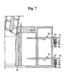
- Fig. 7 shows an apparatus for manufacturing molten irons 200 provided with an apparatus for manufacturing compacted irons 100 according to the first embodiment of the present invention.
- the apparatus for manufacturing molten irons 200 provided with an apparatus for manufacturing compacted irons 100 according to the first embodiment of the present invention is shown in Fig. 8 , this is merely to illustrate the present invention and the present invention is not limited thereto. Therefore, the apparatus for manufacturing molten irons 200 can be provided with an apparatus for manufacturing compacted irons 150 according to the second embodiment of the present invention.
- the apparatus for manufacturing molten irons 200 shown in Fig. 7 includes the apparatus for manufacturing compacted irons 100, a breaker 40, and a melter-gasifier 60.
- the breaker 40 crushes the compacted irons discharged from the apparatus for manufacturing compacted irons 100.
- the compacted irons, which were crushed in the breaker 40 are charged into the melter-gasifier 60 and are melted therein.
- a storage bin 50 for temporarily storing the compacted irons that are crushed in the breaker 40 can be also included. Since the structure of the breaker 40 and the melter-gasifier 60 can be understood by those skilled in the art, a detailed explanation is omitted.
- At least one of the coals selected from the group of lumped coals and coal briquettes are charged into the melter-gasifier 60.
- the lumped coals are coals having grain size of 8mm or more which are gathered from the producing district.
- the coal briquettes are coals which are made by gathering coals having grain size of 8mm or less from the producing district, pulverizing them, and molding them by a press.
- the coal packed bed is formed in the melter-gasifier 60 by charging lumped coals or coal briquettes therein. Oxygen is supplied to the melter-gasifier 60 and then the compacted irons are melted. Molten irons are discharged through a tap. Therefore, it is possible to manufacture molten irons having good quality.
- the apparatus for manufacturing compacted irons according to the present invention includes cheek plates combined with guide tubes, elutriation of the fine reduced irons can be effectively prevented.
- An internal space is formed in the supporter, thereby keeping thermal distribution uniform and so the cheek plates are prevented from staggering due to thermal shock.
- the apparatus for manufacturing compacted irons according to the present invention includes a device for pressing the cheek plates, the cheek plates are effectively pressed.
- the device for pressing the cheek plates is shaped as a bar, the pressing position can be freely adjusted and a plurality of them can be used.
- the cheek plates can be firmly supported.
- the guiding member can be rotated at an approximate right angle, the device for pressing the cheek plates can be easily disassembled.
- the apparatus for manufacturing molten irons according to the present invention includes the above-identified apparatus for manufacturing compacted irons, thereby manufacturing molten irons having good quality.
Landscapes
- Engineering & Computer Science (AREA)
- Mechanical Engineering (AREA)
- Chemical & Material Sciences (AREA)
- General Life Sciences & Earth Sciences (AREA)
- Metallurgy (AREA)
- Geochemistry & Mineralogy (AREA)
- Geology (AREA)
- Manufacturing & Machinery (AREA)
- Life Sciences & Earth Sciences (AREA)
- Materials Engineering (AREA)
- Environmental & Geological Engineering (AREA)
- Organic Chemistry (AREA)
- Manufacture And Refinement Of Metals (AREA)
- Manufacture Of Iron (AREA)
- Press Drives And Press Lines (AREA)
- Treatment Of Steel In Its Molten State (AREA)
- Refinement Of Pig-Iron, Manufacture Of Cast Iron, And Steel Manufacture Other Than In Revolving Furnaces (AREA)
Claims (27)
- Vorrichtung zur Herstellung von kompaktiertem Eisen, mit:- einem Aufgabetrichter (10), in den reduzierte Materialien mit reduziertem Feineisen aufgegeben wird, wobei der Aufgabetrichter sich nach unten erstreckende Führungsrohre (70) hat,- einem Paar von Walzen (20), die im Abstand zueinander stehen und zwischen sich einen Spalt ausbilden,- einem Einfüllkasten (30), um die reduzierten Materialien mit reduziertem Feineisen an das Paar von Walzen zu überführen, gekennzeichnet durch:- ein Paar von Backenplatten (80), welche an den Seiten des Paars von Walzen (20) installiert sind und sich bei Betrachtung in einem Querschnitt parallel zur Ausrichtungsachse der Walzen mit den Führungsrohren (70) überlappen,- wobei auf einem oberen Abschnitt der Backenplatten (80) Nuten (82) ausgebildet sind, die am Einfüllkasten (30) eng anliegen,- die Backenplatten (80) Dichtelemente (84) zur Abdichtung der reduzierten Materialien mit reduziertem Feineisen aufweisen, und wobei die Dichtelemente (84) in den Nuten (82) entlang dieser installiert sind.
- Vorrichtung nach Anspruch 1, bei der Seiten der Dichtelemente (84) an den Nuten (82) anliegen und die Dichtelemente bezüglich der Nuten schräg angestellt sind.
- Vorrichtung nach Anspruch 2, bei der die schräg angestellten Oberflächen der Dichtelemente (84) zur Außenseite des Spaltes weisen.
- Vorrichtung nach Anspruch 2 oder 3, bei der die Dichtelemente (84) den Einfüllkasten (30) tragen.
- Vorrichtung nach einem der Ansprüche 2 bis 4, bei der die Dichtelemente (84) aus warmfesten Stahlplatten gebildet sind.
- Vorrichtung nach Anspruch 1, bei der die Nuten (82) eine erste Nut (822), die entlang der Anordnungsrichtung des Paars von Walzen (20) ausgebildet ist, und zweite Nuten (824) aufweisen, die an die jeweiligen Enden der ersten Nut (822) angeschlossen und entlang der Achsenrichtung des Paars von Walzen (20) ausgebildet sind.
- Vorrichtung nach einem der Ansprüche 1 bis 6, bei der die Länge der Führungsrohre (70) mit deren zunehmendem Abstand vom Zentrum des Spalts größer wird.
- Vorrichtung nach Anspruch 7, bei der ein Endabschnitt (701) und der Bereich um den Endabschnitt der Führungsrohre (70) herum, welcher der längsten Erstreckung der Führungsrohre (70) entspricht, mit einer Oberfläche der Backenplatten (80) überlappen.
- Vorrichtung nach Anspruch 7 oder 8, bei der auf einer zu dem Paar von Walzen (20) hin weisenden Oberfläche der Backenplatten (80) abgeschrägte konkave Abschnitte (86) ausgebildet sind, die mit den Führungsrohren (70) überlappen.
- Vorrichtung nach Anspruch 9, bei der im Zentrum der konkaven Abschnitte (86) der Backenplatten (80) entlang der Anordnungsrichtung der Walzen (20) Stufenabschnitte (861) ausgebildet sind.
- Vorrichtung nach Anspruch 10, bei der an den Führungsrohren (70) Stufenabschnitte (703) ausgebildet sind.
- Vorrichtung nach Anspruch 11, bei der die Stufenabschnitte (861) der Backenplatten (80) den Stufenabschnitten (861) der Führungsrohre (70) jeweils gegenüber liegen.
- Vorrichtung nach einem der Ansprüche 1 bis 12, bei der die Vorrichtung zur Herstellung von kompaktiertem Eisen ferner ein Stützteil (88) zur Abstützung der Backenplatten (80) aufweist, wobei das Stützteil an den beiden entgegengesetzten Seiten des Spalts an den Backenplatten angebracht sind, so dass die Backenplatten (80) zwischen dem Stützteil (88) und dem Spalt zu liegen kommen, und wobei an der den Backenplatten (80)benachbarten Oberfläche des Stützteils (88) Innenräume (89) ausgebildet sind.
- Vorrichtung nach einem der Ansprüche 1 bis 13, mit einer Einheit (90) zum Anpressen der Backenplatten (80) an den Spalt, wobei die Einheit (90) zum Anpressen der Backenplatten bieg- bzw. abknickbar ist.
- Vorrichtung zur Herstellung von kompaktiertem Eisen nach Anspruch 14, bei der die Einheit (90) zum Anpressen der Backenplatten (80):eine Stange (92), von der ein Ende den Backenplatten (80) benachbart ist, um diese anzudrücken und abzustützen, und an deren anderem Ende ein konkaver Abschnitt (921) ausgebildet ist;eine mit dem konkaven Abschnitt (921) der Stange zusammenwirkende Spannspindel (93), deren Außenoberfläche mit Nuten in der Form eines ausgebildeten Gewindes geformt ist;ein Stützelement (94) mit einer Öffnung , durch die sich die Stange (92) erstreckt;einen Block (96) mit einer Öffnung, durch die die Spannspindel im Zusammenwirken mit ihr geschraubt ist;eine in die Spannspindel (93) eingesetzte Feder (98); undein Führungsteil (91) aufweist, das die Spannspindel (93) durchragt und mit beiden Seiten des Stützelements (94) kombiniert ist bzw. in Kombinationseingriff steht.
- Vorrichtung nach Anspruch 15, bei der die Einheit zum Anpressen der Backenplatten als Stange (92) ausgebildet ist.
- Vorrichtung nach Anspruch 15, bei der zumindest drei Einheiten zum Anpressen der Backenplatten installiert sind.
- Vorrichtung nach Anspruch 15, bei der die Einheit zum Anpressen der Backenplatten ferner einen Rahmen (29) aufweist, der an der äußeren Seite des Paars von Walzen (20) installiert ist, wobei sich die Einheit zum Anpressen der Backenplatten in den Rahmen hinein erstreckt und die Backenplatten (80) abstützt.
- Vorrichtung nach Anspruch 15, bei der die Stützelemente (94), der Block (96), die Feder (98) und das Führungsteil (91) miteinander in der Reihenfolge beginnend mit der Stange zur Spannspindel (93) kombiniert bzw. zusammengesetzt sind.
- Vorrichtung nach Anspruch 15, bei der beide Enden des Führungsteils (91) in Pressrichtung ungebogen sind, wobei das Führungsteil mit beiden Seiten des Stützelements (94) in Kombinationseingriff steht.
- Vorrichtung nach Anspruch 20, bei der an der Innenoberfläche beider umgebogener Enden des Führungsteils (91) jeweils ein gestufter Abschnitt (911) ausgebildet ist, um den Block (96) hinsichtlich seiner Bewegung zu beschränken.
- Vorrichtung nach Anspruch 20 oder 21, bei der der Zentrumsabschnitt des Stützelements (94) zwischen den umgebogenen Abschnitten des Führungsteils (91) eingesetzt und mittels Zapfen (905) mit dem Führungsteil zusammengefügt ist.
- Vorrichtung nach Anspruch 22, bei der das Führungsteil (91) unter Zuhilfenahme der Zapfen (905) als Drehachse um annähernd 90 Grad schwenkbar ist.
- Vorrichtung nach einem der Ansprüche 15 bis 23, bei der das Führungsteil (91) den Block (96) und die Seiten der Feder (98) umgibt.
- Vorrichtung nach Anspruch 24, bei der der Block (96) als Rechteckiges Parallelepipedausgebildet ist, wobei beide Seiten des Blocks einer Innenoberfläche des Führungsteils (91) gegenüber liegen.
- Vorrichtung nach einem der Ansprüche 15 bis 25, bei der der Endabschnitt (941) des Stützelements (94) benachbart zum Führungsteil (91) zu seinen beiden Seiten nach außen vorsteht.
- Vorrichtung zur Herstellung von schmelzflüssigem Eisen, mit
der Vorrichtung (100) zur Herstellung von kompaktiertem Eisen nach Anspruch 1;
einem Zerkleinerer (40) zum Zerkleinern von kompaktiertem Eisen, welches von der Vorrichtung (100) zur Herstellung von kompaktiertem Eisen ausgegeben wurde; und
einem Schmelz-Gasifizierer (60), in den das durch den Zerkleinerer (40) zerkleinerte kompaktierte Eisen zugeführt und in dem es geschmolzen wird.
Priority Applications (1)
| Application Number | Priority Date | Filing Date | Title |
|---|---|---|---|
| EP10194663.0A EP2314723B1 (de) | 2004-06-30 | 2005-06-30 | Verfahren zur herstellung von kompaktiertem eisen aus reduzierten materialien, die feines direkt reduziertes eisen umfassen, und vorrichtung zur herstellung von schmelzflüssigem eisen |
Applications Claiming Priority (3)
| Application Number | Priority Date | Filing Date | Title |
|---|---|---|---|
| KR1020040050469A KR101043078B1 (ko) | 2004-06-30 | 2004-06-30 | 치크 플레이트 가압 장치 및 이를 이용한 브리켓 제조장치 |
| KR1020040055556A KR101072490B1 (ko) | 2004-07-16 | 2004-07-16 | 분환원철 함유 환원체의 괴성체 제조 장치 및 이를 이용한용철제조장치 |
| PCT/KR2005/002065 WO2006004350A1 (en) | 2004-06-30 | 2005-06-30 | Apparatus for manufacturing compacted irons of reduced materials comprising fine direct reduced irons and apparatus for manufacturing molten irons using the same |
Related Child Applications (2)
| Application Number | Title | Priority Date | Filing Date |
|---|---|---|---|
| EP10194663.0A Division EP2314723B1 (de) | 2004-06-30 | 2005-06-30 | Verfahren zur herstellung von kompaktiertem eisen aus reduzierten materialien, die feines direkt reduziertes eisen umfassen, und vorrichtung zur herstellung von schmelzflüssigem eisen |
| EP10194663.0 Division-Into | 2010-12-13 |
Publications (3)
| Publication Number | Publication Date |
|---|---|
| EP1776484A1 EP1776484A1 (de) | 2007-04-25 |
| EP1776484A4 EP1776484A4 (de) | 2007-12-26 |
| EP1776484B1 true EP1776484B1 (de) | 2012-03-14 |
Family
ID=35783114
Family Applications (2)
| Application Number | Title | Priority Date | Filing Date |
|---|---|---|---|
| EP05756726A Expired - Lifetime EP1776484B1 (de) | 2004-06-30 | 2005-06-30 | Vorrichtung zur herstellung von kompaktiertem eisen aus reduzierten materialien, die feines direkt reduziertes eisen umfassen, und vorrichtung zur herstellung von schmelzflüssigem eisen |
| EP10194663.0A Expired - Lifetime EP2314723B1 (de) | 2004-06-30 | 2005-06-30 | Verfahren zur herstellung von kompaktiertem eisen aus reduzierten materialien, die feines direkt reduziertes eisen umfassen, und vorrichtung zur herstellung von schmelzflüssigem eisen |
Family Applications After (1)
| Application Number | Title | Priority Date | Filing Date |
|---|---|---|---|
| EP10194663.0A Expired - Lifetime EP2314723B1 (de) | 2004-06-30 | 2005-06-30 | Verfahren zur herstellung von kompaktiertem eisen aus reduzierten materialien, die feines direkt reduziertes eisen umfassen, und vorrichtung zur herstellung von schmelzflüssigem eisen |
Country Status (5)
| Country | Link |
|---|---|
| EP (2) | EP1776484B1 (de) |
| AT (1) | ATE549424T1 (de) |
| BR (1) | BRPI0506142B8 (de) |
| RU (1) | RU2354721C2 (de) |
| WO (1) | WO2006004350A1 (de) |
Families Citing this family (7)
| Publication number | Priority date | Publication date | Assignee | Title |
|---|---|---|---|---|
| KR100797864B1 (ko) * | 2006-12-20 | 2008-01-24 | 주식회사 포스코 | 분환원철 함유 환원체의 괴성체 제조 장치 및 이를 구비한용철제조장치 |
| KR100797838B1 (ko) * | 2006-12-21 | 2008-01-24 | 주식회사 포스코 | 치크 플레이트 가압 장치 |
| AT508930B1 (de) * | 2010-03-04 | 2011-05-15 | Siemens Vai Metals Tech Gmbh | Verfahren und vorrichtung zur herstellung von presslingen |
| KR101649546B1 (ko) * | 2015-10-02 | 2016-08-19 | 주식회사 포스코 | 환원철 괴상화 장치의 치크 플레이트 |
| DE102020104526B4 (de) | 2020-02-20 | 2024-03-28 | Maschinenfabrik Köppern Gmbh & Co. Kg | Hochdruck-Walzenpresse |
| DE102021103573B4 (de) | 2021-02-16 | 2024-06-13 | Maschinenfabrik Köppern Gmbh & Co. Kg | Hochdruck-Walzenpresse |
| DE202021103408U1 (de) | 2021-06-25 | 2022-04-04 | Maschinenfabrik Köppern Gmbh & Co. Kg | Hochdruck-Walzenpresse |
Family Cites Families (16)
| Publication number | Priority date | Publication date | Assignee | Title |
|---|---|---|---|---|
| DE2300702A1 (de) * | 1973-01-08 | 1974-07-11 | Koeppern & Co Kg Maschf | Walzenbrikettpresse |
| US3860376A (en) * | 1973-12-03 | 1975-01-14 | United States Steel Corp | Feed distributor for roll briquetting machine |
| US3883110A (en) * | 1974-06-28 | 1975-05-13 | United States Steel Corp | Briquette mold pocket configuration |
| US4076520A (en) | 1975-06-05 | 1978-02-28 | Midrex Corporation | Method for continuous passivation of sponge iron material |
| US4033559A (en) | 1975-06-05 | 1977-07-05 | Midrex Corporation | Apparatus for continuous passivation of sponge iron material |
| US4093455A (en) | 1975-06-05 | 1978-06-06 | Midrex Corporation | Compacted, passivated metallized iron product |
| JPS59170212A (ja) * | 1983-03-16 | 1984-09-26 | Nippon Steel Corp | 還元鉄ブリケツトの製造方法 |
| JPH01252714A (ja) * | 1988-03-31 | 1989-10-09 | Nippon Steel Corp | 溶融還元炉用混合塊成化ブリケット及び塊成化ブリケットの溶融還元方法 |
| JPH059526A (ja) * | 1991-06-27 | 1993-01-19 | Mitsubishi Heavy Ind Ltd | 銑鉄製造装置 |
| AT404735B (de) | 1992-10-22 | 1999-02-25 | Voest Alpine Ind Anlagen | Verfahren und anlage zur herstellung von flüssigem roheisen oder flüssigen stahlvorprodukten |
| JP3145834B2 (ja) * | 1993-03-08 | 2001-03-12 | 株式会社神戸製鋼所 | 還元鉄ブリケットの製造方法 |
| US5666638A (en) | 1993-09-30 | 1997-09-09 | Maschinenfabrik Koppern Gmbh & Co. Kg | Process for producing sponge iron briquettes from fine ore |
| DE9318843U1 (de) * | 1993-12-08 | 1994-03-17 | Maschinenfabrik Köppern GmbH & Co KG, 45529 Hattingen | Vorrichtung zum Heißbrikettieren von Eisenschwamm |
| US6352573B2 (en) * | 2000-03-21 | 2002-03-05 | Midrex International B.V. Rotterdam | Method for the separation and recycling of hot fines in hot briquetting of reduced iron |
| EP1573076B1 (de) * | 2002-12-21 | 2008-05-21 | Posco | Vorrichtung zur herstellung von schmelzflüssigem eisen durch heissverdichtung von feinem, direkt reduzierten eisen und kalzinierten zusatzstoffen und verfahren zu dessen verwendung |
| MX2007000465A (es) * | 2004-07-12 | 2007-03-08 | Posco | Aparato de manufactura de hierros compactados de materiales reducidos que comprenden hierros finos reducidos directos y aparato de manufactura de hierros fundidos que utiliza el mismo. |
-
2005
- 2005-06-30 BR BRPI0506142A patent/BRPI0506142B8/pt not_active IP Right Cessation
- 2005-06-30 WO PCT/KR2005/002065 patent/WO2006004350A1/en not_active Ceased
- 2005-06-30 EP EP05756726A patent/EP1776484B1/de not_active Expired - Lifetime
- 2005-06-30 RU RU2007101512/02A patent/RU2354721C2/ru not_active IP Right Cessation
- 2005-06-30 EP EP10194663.0A patent/EP2314723B1/de not_active Expired - Lifetime
- 2005-06-30 AT AT05756726T patent/ATE549424T1/de active
Also Published As
| Publication number | Publication date |
|---|---|
| BRPI0506142B8 (pt) | 2017-12-19 |
| RU2007101512A (ru) | 2008-08-10 |
| EP2314723B1 (de) | 2016-03-30 |
| BRPI0506142A8 (pt) | 2017-11-07 |
| WO2006004350A1 (en) | 2006-01-12 |
| ATE549424T1 (de) | 2012-03-15 |
| EP1776484A1 (de) | 2007-04-25 |
| BRPI0506142A (pt) | 2006-10-03 |
| BRPI0506142B1 (pt) | 2013-10-01 |
| RU2354721C2 (ru) | 2009-05-10 |
| EP1776484A4 (de) | 2007-12-26 |
| EP2314723A1 (de) | 2011-04-27 |
Similar Documents
| Publication | Publication Date | Title |
|---|---|---|
| EP1784514B1 (de) | Verfahren zur herstellung von kompaktiertem eisen aus reduzierten materialien, die feines direkt reduziertes eisen umfassen, und vorrichtung zur herstellung von schmelzflüssigem eisen damit | |
| AU2010200684A1 (en) | Apparatus for manufacturing compacted irons of reduced materials comprising fine direct reduced irons and apparatus for manufacturing molten irons using the same | |
| EP1776484B1 (de) | Vorrichtung zur herstellung von kompaktiertem eisen aus reduzierten materialien, die feines direkt reduziertes eisen umfassen, und vorrichtung zur herstellung von schmelzflüssigem eisen | |
| ZA200601407B (en) | Apparatus for manufacturing compacted irons reduced materials comprising fine direct reduced irons and apparatus for manufacturing molten irons using the same | |
| KR101118285B1 (ko) | 분환원철 함유 환원체의 괴성체 제조 장치 및 이를 이용한용철제조장치 | |
| CN1795279B (zh) | 用于制造包含直接还原铁粉的还原材料的压制铁的设备以及使用该设备制造铁水的设备 | |
| KR101072490B1 (ko) | 분환원철 함유 환원체의 괴성체 제조 장치 및 이를 이용한용철제조장치 | |
| EP1781829B1 (de) | Vorrichtung zur herstellung von kompaktiertem eisen aus reduzierten eisenhaltigen feinmaterialien und anlage zur herstellung von schmelzflüssigem eisen unter verwendung dieser vorrichtung | |
| KR101036639B1 (ko) | 분환원철 함유 환원체의 괴성체 제조 장치 및 이를 이용한용철제조장치 | |
| KR101036646B1 (ko) | 분환원철 함유 환원체의 괴성체 제조 장치 및 이를 이용한용철제조장치 | |
| KR101036642B1 (ko) | 분환원철 함유 환원체의 괴성체 제조 장치 및 이를 이용한용철제조장치 | |
| KR101036643B1 (ko) | 분환원철 함유 환원체의 괴성체 제조 장치 및 이를 이용한용철제조장치 | |
| KR100711765B1 (ko) | 분환원철 함유 환원체의 괴성체 제조 장치 및 이를 구비한용철제조장치 | |
| KR100711764B1 (ko) | 분환원철 함유 환원체의 괴성체 제조 장치 및 이를 구비한용철제조장치 | |
| KR101036641B1 (ko) | 분환원철 함유 환원체의 괴성체 제조 장치 및 이를 이용한용철제조장치 | |
| KR101036644B1 (ko) | 분환원철 함유 환원체의 괴성체 제조 장치 및 이를 이용한용철제조장치 | |
| WO2008075845A1 (en) | Apparatus for manufacturing compacted irons of reduced materials comprising fine direct reduced irons and apparatus for manufacturing molten irons provided with the same | |
| RU2354722C2 (ru) | Устройство для производства спрессованного железа из восстановленных материалов, содержащих мелкодисперсное восстановленное железо, и установка для производства расплавленного железа, включающая устройство для производства спрессованного железа |
Legal Events
| Date | Code | Title | Description |
|---|---|---|---|
| PUAI | Public reference made under article 153(3) epc to a published international application that has entered the european phase |
Free format text: ORIGINAL CODE: 0009012 |
|
| 17P | Request for examination filed |
Effective date: 20070123 |
|
| AK | Designated contracting states |
Kind code of ref document: A1 Designated state(s): AT BE BG CH CY CZ DE DK EE ES FI FR GB GR HU IE IS IT LI LT LU MC NL PL PT RO SE SI SK TR |
|
| DAX | Request for extension of the european patent (deleted) | ||
| A4 | Supplementary search report drawn up and despatched |
Effective date: 20071127 |
|
| 17Q | First examination report despatched |
Effective date: 20081202 |
|
| GRAP | Despatch of communication of intention to grant a patent |
Free format text: ORIGINAL CODE: EPIDOSNIGR1 |
|
| GRAS | Grant fee paid |
Free format text: ORIGINAL CODE: EPIDOSNIGR3 |
|
| GRAA | (expected) grant |
Free format text: ORIGINAL CODE: 0009210 |
|
| AK | Designated contracting states |
Kind code of ref document: B1 Designated state(s): AT BE BG CH CY CZ DE DK EE ES FI FR GB GR HU IE IS IT LI LT LU MC NL PL PT RO SE SI SK TR |
|
| REG | Reference to a national code |
Ref country code: GB Ref legal event code: FG4D |
|
| REG | Reference to a national code |
Ref country code: CH Ref legal event code: EP Ref country code: AT Ref legal event code: REF Ref document number: 549424 Country of ref document: AT Kind code of ref document: T Effective date: 20120315 |
|
| REG | Reference to a national code |
Ref country code: IE Ref legal event code: FG4D |
|
| REG | Reference to a national code |
Ref country code: DE Ref legal event code: R096 Ref document number: 602005033161 Country of ref document: DE Effective date: 20120510 |
|
| REG | Reference to a national code |
Ref country code: NL Ref legal event code: VDEP Effective date: 20120314 |
|
| PG25 | Lapsed in a contracting state [announced via postgrant information from national office to epo] |
Ref country code: LT Free format text: LAPSE BECAUSE OF FAILURE TO SUBMIT A TRANSLATION OF THE DESCRIPTION OR TO PAY THE FEE WITHIN THE PRESCRIBED TIME-LIMIT Effective date: 20120314 |
|
| LTIE | Lt: invalidation of european patent or patent extension |
Effective date: 20120314 |
|
| PG25 | Lapsed in a contracting state [announced via postgrant information from national office to epo] |
Ref country code: FI Free format text: LAPSE BECAUSE OF FAILURE TO SUBMIT A TRANSLATION OF THE DESCRIPTION OR TO PAY THE FEE WITHIN THE PRESCRIBED TIME-LIMIT Effective date: 20120314 Ref country code: GR Free format text: LAPSE BECAUSE OF FAILURE TO SUBMIT A TRANSLATION OF THE DESCRIPTION OR TO PAY THE FEE WITHIN THE PRESCRIBED TIME-LIMIT Effective date: 20120615 |
|
| PG25 | Lapsed in a contracting state [announced via postgrant information from national office to epo] |
Ref country code: CY Free format text: LAPSE BECAUSE OF FAILURE TO SUBMIT A TRANSLATION OF THE DESCRIPTION OR TO PAY THE FEE WITHIN THE PRESCRIBED TIME-LIMIT Effective date: 20120314 |
|
| PG25 | Lapsed in a contracting state [announced via postgrant information from national office to epo] |
Ref country code: EE Free format text: LAPSE BECAUSE OF FAILURE TO SUBMIT A TRANSLATION OF THE DESCRIPTION OR TO PAY THE FEE WITHIN THE PRESCRIBED TIME-LIMIT Effective date: 20120314 Ref country code: BE Free format text: LAPSE BECAUSE OF FAILURE TO SUBMIT A TRANSLATION OF THE DESCRIPTION OR TO PAY THE FEE WITHIN THE PRESCRIBED TIME-LIMIT Effective date: 20120314 Ref country code: IS Free format text: LAPSE BECAUSE OF FAILURE TO SUBMIT A TRANSLATION OF THE DESCRIPTION OR TO PAY THE FEE WITHIN THE PRESCRIBED TIME-LIMIT Effective date: 20120714 Ref country code: PL Free format text: LAPSE BECAUSE OF FAILURE TO SUBMIT A TRANSLATION OF THE DESCRIPTION OR TO PAY THE FEE WITHIN THE PRESCRIBED TIME-LIMIT Effective date: 20120314 Ref country code: SI Free format text: LAPSE BECAUSE OF FAILURE TO SUBMIT A TRANSLATION OF THE DESCRIPTION OR TO PAY THE FEE WITHIN THE PRESCRIBED TIME-LIMIT Effective date: 20120314 Ref country code: RO Free format text: LAPSE BECAUSE OF FAILURE TO SUBMIT A TRANSLATION OF THE DESCRIPTION OR TO PAY THE FEE WITHIN THE PRESCRIBED TIME-LIMIT Effective date: 20120314 Ref country code: CZ Free format text: LAPSE BECAUSE OF FAILURE TO SUBMIT A TRANSLATION OF THE DESCRIPTION OR TO PAY THE FEE WITHIN THE PRESCRIBED TIME-LIMIT Effective date: 20120314 Ref country code: SE Free format text: LAPSE BECAUSE OF FAILURE TO SUBMIT A TRANSLATION OF THE DESCRIPTION OR TO PAY THE FEE WITHIN THE PRESCRIBED TIME-LIMIT Effective date: 20120314 |
|
| PG25 | Lapsed in a contracting state [announced via postgrant information from national office to epo] |
Ref country code: PT Free format text: LAPSE BECAUSE OF FAILURE TO SUBMIT A TRANSLATION OF THE DESCRIPTION OR TO PAY THE FEE WITHIN THE PRESCRIBED TIME-LIMIT Effective date: 20120716 Ref country code: SK Free format text: LAPSE BECAUSE OF FAILURE TO SUBMIT A TRANSLATION OF THE DESCRIPTION OR TO PAY THE FEE WITHIN THE PRESCRIBED TIME-LIMIT Effective date: 20120314 |
|
| PLBE | No opposition filed within time limit |
Free format text: ORIGINAL CODE: 0009261 |
|
| STAA | Information on the status of an ep patent application or granted ep patent |
Free format text: STATUS: NO OPPOSITION FILED WITHIN TIME LIMIT |
|
| PG25 | Lapsed in a contracting state [announced via postgrant information from national office to epo] |
Ref country code: NL Free format text: LAPSE BECAUSE OF FAILURE TO SUBMIT A TRANSLATION OF THE DESCRIPTION OR TO PAY THE FEE WITHIN THE PRESCRIBED TIME-LIMIT Effective date: 20120314 Ref country code: MC Free format text: LAPSE BECAUSE OF NON-PAYMENT OF DUE FEES Effective date: 20120630 Ref country code: DK Free format text: LAPSE BECAUSE OF FAILURE TO SUBMIT A TRANSLATION OF THE DESCRIPTION OR TO PAY THE FEE WITHIN THE PRESCRIBED TIME-LIMIT Effective date: 20120314 |
|
| REG | Reference to a national code |
Ref country code: CH Ref legal event code: PL |
|
| REG | Reference to a national code |
Ref country code: CH Ref legal event code: PL |
|
| 26N | No opposition filed |
Effective date: 20121217 |
|
| GBPC | Gb: european patent ceased through non-payment of renewal fee |
Effective date: 20120630 |
|
| PG25 | Lapsed in a contracting state [announced via postgrant information from national office to epo] |
Ref country code: IT Free format text: LAPSE BECAUSE OF FAILURE TO SUBMIT A TRANSLATION OF THE DESCRIPTION OR TO PAY THE FEE WITHIN THE PRESCRIBED TIME-LIMIT Effective date: 20120314 |
|
| REG | Reference to a national code |
Ref country code: IE Ref legal event code: MM4A |
|
| REG | Reference to a national code |
Ref country code: DE Ref legal event code: R097 Ref document number: 602005033161 Country of ref document: DE Effective date: 20121217 |
|
| PG25 | Lapsed in a contracting state [announced via postgrant information from national office to epo] |
Ref country code: ES Free format text: LAPSE BECAUSE OF FAILURE TO SUBMIT A TRANSLATION OF THE DESCRIPTION OR TO PAY THE FEE WITHIN THE PRESCRIBED TIME-LIMIT Effective date: 20120625 Ref country code: LI Free format text: LAPSE BECAUSE OF NON-PAYMENT OF DUE FEES Effective date: 20120630 Ref country code: GB Free format text: LAPSE BECAUSE OF NON-PAYMENT OF DUE FEES Effective date: 20120630 Ref country code: CH Free format text: LAPSE BECAUSE OF NON-PAYMENT OF DUE FEES Effective date: 20120630 Ref country code: IE Free format text: LAPSE BECAUSE OF NON-PAYMENT OF DUE FEES Effective date: 20120630 |
|
| PG25 | Lapsed in a contracting state [announced via postgrant information from national office to epo] |
Ref country code: BG Free format text: LAPSE BECAUSE OF FAILURE TO SUBMIT A TRANSLATION OF THE DESCRIPTION OR TO PAY THE FEE WITHIN THE PRESCRIBED TIME-LIMIT Effective date: 20120614 |
|
| PG25 | Lapsed in a contracting state [announced via postgrant information from national office to epo] |
Ref country code: TR Free format text: LAPSE BECAUSE OF FAILURE TO SUBMIT A TRANSLATION OF THE DESCRIPTION OR TO PAY THE FEE WITHIN THE PRESCRIBED TIME-LIMIT Effective date: 20120314 |
|
| PG25 | Lapsed in a contracting state [announced via postgrant information from national office to epo] |
Ref country code: LU Free format text: LAPSE BECAUSE OF NON-PAYMENT OF DUE FEES Effective date: 20120630 |
|
| PG25 | Lapsed in a contracting state [announced via postgrant information from national office to epo] |
Ref country code: HU Free format text: LAPSE BECAUSE OF FAILURE TO SUBMIT A TRANSLATION OF THE DESCRIPTION OR TO PAY THE FEE WITHIN THE PRESCRIBED TIME-LIMIT Effective date: 20050630 |
|
| REG | Reference to a national code |
Ref country code: FR Ref legal event code: PLFP Year of fee payment: 11 |
|
| REG | Reference to a national code |
Ref country code: FR Ref legal event code: PLFP Year of fee payment: 12 |
|
| REG | Reference to a national code |
Ref country code: FR Ref legal event code: PLFP Year of fee payment: 13 |
|
| REG | Reference to a national code |
Ref country code: FR Ref legal event code: PLFP Year of fee payment: 14 |
|
| PGFP | Annual fee paid to national office [announced via postgrant information from national office to epo] |
Ref country code: DE Payment date: 20190520 Year of fee payment: 15 |
|
| PGFP | Annual fee paid to national office [announced via postgrant information from national office to epo] |
Ref country code: FR Payment date: 20190522 Year of fee payment: 15 |
|
| PGFP | Annual fee paid to national office [announced via postgrant information from national office to epo] |
Ref country code: AT Payment date: 20190520 Year of fee payment: 15 |
|
| REG | Reference to a national code |
Ref country code: DE Ref legal event code: R119 Ref document number: 602005033161 Country of ref document: DE |
|
| REG | Reference to a national code |
Ref country code: AT Ref legal event code: MM01 Ref document number: 549424 Country of ref document: AT Kind code of ref document: T Effective date: 20200630 |
|
| PG25 | Lapsed in a contracting state [announced via postgrant information from national office to epo] |
Ref country code: FR Free format text: LAPSE BECAUSE OF NON-PAYMENT OF DUE FEES Effective date: 20200630 |
|
| PG25 | Lapsed in a contracting state [announced via postgrant information from national office to epo] |
Ref country code: AT Free format text: LAPSE BECAUSE OF NON-PAYMENT OF DUE FEES Effective date: 20200630 Ref country code: DE Free format text: LAPSE BECAUSE OF NON-PAYMENT OF DUE FEES Effective date: 20210101 |