EP1776851A1 - Arrangement to control automatically the working width of a plough - Google Patents
Arrangement to control automatically the working width of a plough Download PDFInfo
- Publication number
- EP1776851A1 EP1776851A1 EP06021740A EP06021740A EP1776851A1 EP 1776851 A1 EP1776851 A1 EP 1776851A1 EP 06021740 A EP06021740 A EP 06021740A EP 06021740 A EP06021740 A EP 06021740A EP 1776851 A1 EP1776851 A1 EP 1776851A1
- Authority
- EP
- European Patent Office
- Prior art keywords
- plough
- working width
- gps
- antenna
- arrangement
- Prior art date
- Legal status (The legal status is an assumption and is not a legal conclusion. Google has not performed a legal analysis and makes no representation as to the accuracy of the status listed.)
- Granted
Links
Images
Classifications
-
- A—HUMAN NECESSITIES
- A01—AGRICULTURE; FORESTRY; ANIMAL HUSBANDRY; HUNTING; TRAPPING; FISHING
- A01B—SOIL WORKING IN AGRICULTURE OR FORESTRY; PARTS, DETAILS, OR ACCESSORIES OF AGRICULTURAL MACHINES OR IMPLEMENTS, IN GENERAL
- A01B63/00—Lifting or adjusting devices or arrangements for agricultural machines or implements
- A01B63/02—Lifting or adjusting devices or arrangements for agricultural machines or implements for implements mounted on tractors
- A01B63/023—Lateral adjustment of their tools
Definitions
- the present invention relates to an arrangement to automatically control the working width of a plough.
- This arrangement comprises a gps-antenna which is part of a global positioning system.
- the gps-antenna serves to receive signals from one or more gps-satellites. Based on these signals a micro processor calculates the instantaneous position of the gps-antenna and compares this "ist" position with a pre-determined "soll” position. If the "ist"position does not comply with the "soll” position, the micro processor may command one or more actuators controlling the working width of the plough.
- the object of the present invention is to provide an arrangement to control the ploughing width with an improved degree of accuracy by introducing a mechanical feed back being part of the working width control mechanism.
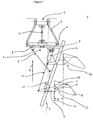
- Fig. 1 shows schematically a plane view from above of a well known plough 1 with means to adjust the working width.
- Plough headstock 2 is mounted to the back of a tractor 5 by means of two towing linkages 3 and 3' and a top linkage 5. Both ends of towing linkages 3 and 3' and top linkage 5 are provided with ball-and-socket joints. Seen from above, this mounting means allows the plough to swing sideways to some extend.
- Plough frame 8 is connected to plough headstock 2 by means of sliding 7.
- the angle between plough headstock 2 and plough frame 8 depends on the length of bracket 9.
- Bracket 9 may be in the form of a spindle or a hydraulic cylinder.
- a front plough member 10 and a rear plough member 11 are pivotably mounted on plough frame 8 by means of brackets 12 and 12'.
- Brackets 12 and 12' are interconnected by steering linkage 13.
- the angle between the brackets 12, 12' and plough frame 8 can be adjusted by means of plough width cylinder 14.
- One end of plough width cylinder 14 is connected to the steering linkage 13 and the other end to plough frame 8 or plough headstock 2 or to both depending on the type of plough.
- Plough members 10 and 11 usually comprise among others a plough beam 15, 15', a plough body 16, 16', a landside 17, 17', a plough share 18, 18' and a mouldboard 19, 19'.
- Plough 1 is further provided with a gps-antenna 20.
- Fig. 1 shows a conventional, one way plough. The invention also applies to two way reversible and swing ploughs.
- the nominal working width is calculated by multiplying the number of plough members 10, 11 by the distance l 1 between adjacent plough members.
- the distance l 1 can be adjusted by means of the plough width cylinder 14.
- the length of plough width cylinder 14 is positively correlated with the working width.
- the actual working width may however differ from the nominal working width as is explained hereafter.
- the soil force acting on a plough member 10, 11 is partly transferred by the landside 17 on the side of the plough furrow.
- the size of the landside is such that it moves exactly or near parallel to the direction of driving R along the furrow side when the plough is properly adjusted.
- the adjustment of the working width of the first plough member 10 is based on this characteristic.
- the working width of the first plough member 10 should equal l 1 .
- Plough frame 8 with sliding 7 can slide along plough headstock 2 by means of a spindle or a hydraulic cylinder (not shown).
- the working width needs to be adjusted when the field borderline runs parallel to the plough furrow, but the distance between the borderline and the furrow does not equal a multiple of the actual working width. Adjustment of the working width during ploughing is required to make the borderline and the furrow run parallel.
- the imprint of the landside 17, 17" in the furrow side may vary depending on the soil force acting on the front part of a plough member 10, 11 and the resistance to failure of the soil along the furrow side. Variation may occur when soil changes from coarse textured into a finer texture during ploughing on a given field. It is common practise that the working width increases when the soil changes from a coarse into a finer texture. If so, the plough in Fig. 1 swings to the left, unploughed side. The increase of the working width is almost completely the result of the increasing working width of the first plough member 10. The following plough members add relatively very little to this.
- the uncontrolled variation of the working width of a plough is very inconvenient for various reasons, e.g. when finishing up a field. Swinging of the plough also affects the position of the virtual towing point at the intersection of the produced parts of the towing linkages 3 and 3'. Variation of the position of the towing point may adversely affect the course stability of the tractor-plough combination.
- the tractor operator has three options to adjust the working width when ploughing wider when the soil changes from a coarse into a finer texture:
- option b. is to be preferred as it only changes the working width of the first plough member 10 and it brings back the towing point in the original, preferred position.
- the very sensitive response of the working width to changing the angle between the plough headstock 12 and the plough frame 8 is a serious drawback of option b.
- Option a. compensates for the increase of the working width of plough member 10 only. Changing the position of sliding 7 has no significant effect on the position of the towing point.
- option c. is the less favourable.
- Option c. compensates for the increase of the working width of the first plough member 10 by decreasing the working width of all plough members equally. The working width of the first plough member 10 remains greater than the working width of the other members.
- Option c. does not bring the towing point back in the original position.
- the field to be ploughed is provided with a virtual pattern of lines L to be followed by a defined point on the plough.
- the coordinates of the points defining the lines L are for instance designed by geo-processing of a digital map of the field to be ploughed.
- the distance between the lines equals the desired working width.
- These virtual ploughing lines may run parallel, may diverge or converge or may be straight or bending.
- the gps-antenna 20 is mounted on a plough so as to avoid interference by any plough or tractor part when receiving the satellite signal(s). Furthermore, the plough or tractor is equipped with a micro-processor comparing the actual "ist"-position with the desired "soll”-position. If needed, the micro processor sends a command to the plough to alter its working width.
- the gps-antenna 20 is mounted on a plough.
- the gps-antenna 20 is mounted on one of the plough members 10,11.
- the gsp-antenna 20 is mounted on the bracket 12 of the rear plough member 11. This plough member acts most sensitive to adjustment of the working width of the plough and swinging of the plough with respect to the tractor.
- This plough member acts most sensitive to adjustment of the working width of the plough and swinging of the plough with respect to the tractor.
- the position of the gps-antenna 20 with reference to the pivot joint of the bracket 12, 12' of the plough members 10,11.
- the gps-antenna 20 is positioned in a geometrical plane that, seen from above and in the driving direction, is bound at the rear by a line running at right angles to the direction of driving R and intersecting the pivot joint of the plough member where it is mounted on. This particular position of the gps-antenna 20 with respect of the plough generates a mechanical feed back in the control mechanism of the working width of the plough.
- the instantaneous working width of a plough is correct when the centre of the gps-antenna 20 follows the virtual plough line L .
- the micro processor commands the hydraulic system to retract the hydraulic cylinder 14 that operates the steering linkage.
- the brackets 12, 12' including the plough members 10, 11 and the gps-antenna 20 rotate clockwise with reference to the plough frame 8 in Fig. 1.
- the plough members 10, 11 move sideways with respect of the direction of driving R , in the direction of plough line L .
- This sideway movement stops as soon as the plough members 10, 11 retain the directional position, with reference to the direction of driving R , as before the adjustment.
- a new state of equilibrium has come into being.
- the gps-antenna 20 also rotates around the pivot joint in the direction of the virtual plough line L .
- the micro processor stops activating the hydraulic system. At that very moment, the plough is at or near its new state of equilibrium. This mechanical feed back forming a part of the plough width control mechanism effectively reduces oversteering and swinging of the plough to an acceptable level.
Landscapes
- Life Sciences & Earth Sciences (AREA)
- Engineering & Computer Science (AREA)
- Mechanical Engineering (AREA)
- Soil Sciences (AREA)
- Environmental Sciences (AREA)
- Lifting Devices For Agricultural Implements (AREA)
- Soil Working Implements (AREA)
- Position Fixing By Use Of Radio Waves (AREA)
- Guiding Agricultural Machines (AREA)
- Harvester Elements (AREA)
Abstract
Description
- The present invention relates to an arrangement to automatically control the working width of a plough. This arrangement comprises a gps-antenna which is part of a global positioning system. The gps-antenna serves to receive signals from one or more gps-satellites. Based on these signals a micro processor calculates the instantaneous position of the gps-antenna and compares this "ist" position with a pre-determined "soll" position. If the "ist"position does not comply with the "soll" position, the micro processor may command one or more actuators controlling the working width of the plough.
- Arrangements of the above type are known from example from
US 2003/0.208.311 A . The object of the present invention is to provide an arrangement to control the ploughing width with an improved degree of accuracy by introducing a mechanical feed back being part of the working width control mechanism. Some general aspects of the dynamics of ploughing, with particular reference to working width, are briefly described by reference to a schematical illustration of a plough in Fig. 1. - Fig. 1 shows schematically a plane view from above of a well known plough 1 with means to adjust the working width. Plough headstock 2 is mounted to the back of a
tractor 5 by means of twotowing linkages 3 and 3' and atop linkage 5. Both ends oftowing linkages 3 and 3' andtop linkage 5 are provided with ball-and-socket joints. Seen from above, this mounting means allows the plough to swing sideways to some extend. - Plough frame 8 is connected to plough headstock 2 by means of sliding 7. The angle between plough headstock 2 and plough frame 8 depends on the length of bracket 9. Bracket 9 may be in the form of a spindle or a hydraulic cylinder. A front plough member 10 and a rear plough member 11 are pivotably mounted on plough frame 8 by means of
brackets 12 and 12'.Brackets 12 and 12' are interconnected bysteering linkage 13. The angle between thebrackets 12, 12' and plough frame 8 can be adjusted by means ofplough width cylinder 14. One end ofplough width cylinder 14 is connected to thesteering linkage 13 and the other end to plough frame 8 or plough headstock 2 or to both depending on the type of plough. Plough members 10 and 11 usually comprise among others aplough beam 15, 15', a plough body 16, 16', alandside 17, 17', aplough share 18, 18' and a mouldboard 19, 19'. Plough 1 is further provided with a gps-antenna 20. Fig. 1 shows a conventional, one way plough. The invention also applies to two way reversible and swing ploughs. - The nominal working width is calculated by multiplying the number of plough members 10, 11 by the distance ℓ1 between adjacent plough members. The distance ℓ1 can be adjusted by means of the
plough width cylinder 14. The length ofplough width cylinder 14 is positively correlated with the working width. The actual working width may however differ from the nominal working width as is explained hereafter. - During ploughing, the soil force acting on a plough member 10, 11 is partly transferred by the
landside 17 on the side of the plough furrow. The size of the landside is such that it moves exactly or near parallel to the direction of driving R along the furrow side when the plough is properly adjusted. The adjustment of the working width of the first plough member 10 is based on this characteristic. The working width of the first plough member 10 should equal ℓ1. Plough frame 8 with sliding 7 can slide along plough headstock 2 by means of a spindle or a hydraulic cylinder (not shown). - There are two important reasons for the plough operator to adjust the working width of a plough:
- To end parallel to the field borderline;
- To straighten a bended furrow.
- The working width needs to be adjusted when the field borderline runs parallel to the plough furrow, but the distance between the borderline and the furrow does not equal a multiple of the actual working width. Adjustment of the working width during ploughing is required to make the borderline and the furrow run parallel.
- The imprint of the
landside - The uncontrolled variation of the working width of a plough is very inconvenient for various reasons, e.g. when finishing up a field. Swinging of the plough also affects the position of the virtual towing point at the intersection of the produced parts of the
towing linkages 3 and 3'. Variation of the position of the towing point may adversely affect the course stability of the tractor-plough combination. - The tractor operator has three options to adjust the working width when ploughing wider when the soil changes from a coarse into a finer texture:
- a. Moving the sliding 7 in the direction of the unploughed by means of a spindle or a hydraulic cylinder.
- b. Decrease the angle between the plough headstock 2 and the plough frame 8.
- c. Decrease the working width by shortening the working
width cylinder 14. - From a theoretical point of view, option b. is to be preferred as it only changes the working width of the first plough member 10 and it brings back the towing point in the original, preferred position. The very sensitive response of the working width to changing the angle between the
plough headstock 12 and the plough frame 8 is a serious drawback of option b. Option a. compensates for the increase of the working width of plough member 10 only. Changing the position of sliding 7 has no significant effect on the position of the towing point.
From a theoretical point of view, option c. is the less favourable. Option c. compensates for the increase of the working width of the first plough member 10 by decreasing the working width of all plough members equally. The working width of the first plough member 10 remains greater than the working width of the other members. Option c. does not bring the towing point back in the original position. - From a technical point of view it is possible to design a gps-controlled plough with arrangements to assess and control the working width of the first plough member and arrangements to assess and control the working width of the plough. Under practical conditions however it suffices to control the working width of the plough, provided that the accuracy of the gps-control mechanism meets the demands.
- When applying gps to control the working width of a plough it is assumed that the field to be ploughed is provided with a virtual pattern of lines L to be followed by a defined point on the plough. The coordinates of the points defining the lines L are for instance designed by geo-processing of a digital map of the field to be ploughed. The distance between the lines equals the desired working width. These virtual ploughing lines may run parallel, may diverge or converge or may be straight or bending.
- The gps-
antenna 20 is mounted on a plough so as to avoid interference by any plough or tractor part when receiving the satellite signal(s). Furthermore, the plough or tractor is equipped with a micro-processor comparing the actual "ist"-position with the desired "soll"-position. If needed, the micro processor sends a command to the plough to alter its working width. - Of particular relevance is the position where the gps-
antenna 20 is mounted on a plough. According to the invention, the gps-antenna 20 is mounted on one of the plough members 10,11. In a preferred embodiment, the gsp-antenna 20 is mounted on thebracket 12 of the rear plough member 11. This plough member acts most sensitive to adjustment of the working width of the plough and swinging of the plough with respect to the tractor. Of particular relevance is further the position of the gps-antenna 20 with reference to the pivot joint of thebracket 12, 12' of the plough members 10,11. According to a preferred embodiment of the invention, the gps-antenna 20 is positioned in a geometrical plane that, seen from above and in the driving direction, is bound at the rear by a line running at right angles to the direction of driving R and intersecting the pivot joint of the plough member where it is mounted on. This particular position of the gps-antenna 20 with respect of the plough generates a mechanical feed back in the control mechanism of the working width of the plough. - The effectiveness of the arrangement according to the invention will now be elucidated by reference to the embodiment illustrated schematically in Fig. 1.
- The instantaneous working width of a plough is correct when the centre of the gps-
antenna 20 follows the virtual plough line L . Assume now, that the gps-antenna 20 starts to deviate from the plough line L in the direction of the unploughed part of the field. When the deviation exceeds a predefined threshold value, the micro processor commands the hydraulic system to retract thehydraulic cylinder 14 that operates the steering linkage. As a result, thebrackets 12, 12' including the plough members 10, 11 and the gps-antenna 20 rotate clockwise with reference to the plough frame 8 in Fig. 1. As a result of this rotation, the plough members 10, 11 move sideways with respect of the direction of driving R, in the direction of plough line L. This sideway movement stops as soon as the plough members 10, 11 retain the directional position, with reference to the direction of driving R, as before the adjustment. A new state of equilibrium has come into being. During the rotation of the plough members 10,11 with respect to the plough frame 8, the gps-antenna 20 also rotates around the pivot joint in the direction of the virtual plough line L. As soon as the gps-antenna 20 intersects the dead band of the plough line L, the micro processor stops activating the hydraulic system. At that very moment, the plough is at or near its new state of equilibrium. This mechanical feed back forming a part of the plough width control mechanism effectively reduces oversteering and swinging of the plough to an acceptable level.
Claims (3)
- Arrangement to assess and control the working width of a plough, including a gps-antenna 20 to assess the instantaneous position of a point on said plough with reference to a virtual plough line L,
characterised in that the gps-antenna 20 is mounted on a plough member 10,11, said plough member being pivotably mounted on the plough frame 8 of said plough. - Plough with gps-antenna 20 according to claim 1,
characterised in that the gps-antenna 20 is positioned in a geometrical plane that, seen from above and in the driving direction R, is bound at the rear by a line running at right angles to the driving direction R and intersecting the pivot joint of the plough member it is mounted on. - Plough with GPS antenna according to claim 1,
characterised in that the gps-antenna 20 is mounted on the last plough member 11, said plough member is mounted on the back of the plough frame 8.
Priority Applications (1)
| Application Number | Priority Date | Filing Date | Title |
|---|---|---|---|
| PL06021740T PL1776851T5 (en) | 2005-10-18 | 2006-10-18 | Arrangement to control automatically the working width of a plough |
Applications Claiming Priority (1)
| Application Number | Priority Date | Filing Date | Title |
|---|---|---|---|
| NL1030219A NL1030219C2 (en) | 2005-10-18 | 2005-10-18 | Device for automatically controlling the working width of a team. |
Publications (3)
| Publication Number | Publication Date |
|---|---|
| EP1776851A1 true EP1776851A1 (en) | 2007-04-25 |
| EP1776851B1 EP1776851B1 (en) | 2011-07-20 |
| EP1776851B2 EP1776851B2 (en) | 2014-09-17 |
Family
ID=37622079
Family Applications (1)
| Application Number | Title | Priority Date | Filing Date |
|---|---|---|---|
| EP06021740.3A Not-in-force EP1776851B2 (en) | 2005-10-18 | 2006-10-18 | Arrangement to control automatically the working width of a plough |
Country Status (6)
| Country | Link |
|---|---|
| EP (1) | EP1776851B2 (en) |
| AT (1) | ATE516697T1 (en) |
| DK (1) | DK1776851T4 (en) |
| ES (1) | ES2369146T5 (en) |
| NL (1) | NL1030219C2 (en) |
| PL (1) | PL1776851T5 (en) |
Cited By (3)
| Publication number | Priority date | Publication date | Assignee | Title |
|---|---|---|---|---|
| DE102021132869A1 (en) | 2021-12-14 | 2023-06-15 | Amazonen-Werke H. Dreyer SE & Co. KG | Method of determining correction settings for an agricultural plow |
| US20230189682A1 (en) * | 2019-07-18 | 2023-06-22 | Roberts Welding & Fabricating Ltd. | Removably mounted plow for elongated tubular materials |
| EP4620280A1 (en) | 2024-02-26 | 2025-09-24 | Lemken GmbH & Co KG | Method for determining a correct adjustment for a plough |
Families Citing this family (2)
| Publication number | Priority date | Publication date | Assignee | Title |
|---|---|---|---|---|
| DK178793B1 (en) * | 2015-07-08 | 2017-02-20 | Agro Intelligence Aps | A plough system and a method for ploughing |
| EP4555840A1 (en) * | 2023-11-17 | 2025-05-21 | Overum Industries AB | A controller for a plough, a plough system and associated methods |
Citations (5)
| Publication number | Priority date | Publication date | Assignee | Title |
|---|---|---|---|---|
| US3537531A (en) * | 1968-07-23 | 1970-11-03 | Int Harvester Co | Automatic guidance apparatus for vehicles |
| DE3345231C1 (en) * | 1983-12-14 | 1985-03-21 | Xaver Fendt & Co, 8952 Marktoberdorf | Control process and devices for operating a combination consisting of a farm tractor and of a plough |
| WO2002080652A1 (en) * | 2001-04-09 | 2002-10-17 | Beeline Technologies Pty Ltd | Soil cultivation implement control apparatus and method |
| EP1338186A2 (en) * | 2002-02-26 | 2003-08-27 | CLAAS Selbstfahrende Erntemaschinen GmbH | Agricultural working machine track steering system |
| US20030208311A1 (en) * | 2002-05-06 | 2003-11-06 | Mcclure John A. | Method and system for implement steering for agricultural vehicles |
Family Cites Families (3)
| Publication number | Priority date | Publication date | Assignee | Title |
|---|---|---|---|---|
| DE19961442A1 (en) † | 1999-12-20 | 2001-07-12 | Griepentrog Hans Werner | Appliance for controlling agricultural machines based on the position of plants previously determined by employing a GPS system |
| DE10039600B4 (en) † | 2000-08-12 | 2016-01-14 | Lemken Gmbh & Co. Kg | Multi-share rotary plow |
| DE10303516A1 (en) † | 2003-01-30 | 2004-08-12 | Amazonen-Werke H. Dreyer Gmbh & Co. Kg | Device for working and / or cultivating agricultural land |
-
2005
- 2005-10-18 NL NL1030219A patent/NL1030219C2/en not_active IP Right Cessation
-
2006
- 2006-10-18 PL PL06021740T patent/PL1776851T5/en unknown
- 2006-10-18 EP EP06021740.3A patent/EP1776851B2/en not_active Not-in-force
- 2006-10-18 AT AT06021740T patent/ATE516697T1/en active
- 2006-10-18 ES ES06021740.3T patent/ES2369146T5/en active Active
- 2006-10-18 DK DK06021740.3T patent/DK1776851T4/en active
Patent Citations (5)
| Publication number | Priority date | Publication date | Assignee | Title |
|---|---|---|---|---|
| US3537531A (en) * | 1968-07-23 | 1970-11-03 | Int Harvester Co | Automatic guidance apparatus for vehicles |
| DE3345231C1 (en) * | 1983-12-14 | 1985-03-21 | Xaver Fendt & Co, 8952 Marktoberdorf | Control process and devices for operating a combination consisting of a farm tractor and of a plough |
| WO2002080652A1 (en) * | 2001-04-09 | 2002-10-17 | Beeline Technologies Pty Ltd | Soil cultivation implement control apparatus and method |
| EP1338186A2 (en) * | 2002-02-26 | 2003-08-27 | CLAAS Selbstfahrende Erntemaschinen GmbH | Agricultural working machine track steering system |
| US20030208311A1 (en) * | 2002-05-06 | 2003-11-06 | Mcclure John A. | Method and system for implement steering for agricultural vehicles |
Cited By (4)
| Publication number | Priority date | Publication date | Assignee | Title |
|---|---|---|---|---|
| US20230189682A1 (en) * | 2019-07-18 | 2023-06-22 | Roberts Welding & Fabricating Ltd. | Removably mounted plow for elongated tubular materials |
| US12557721B2 (en) * | 2019-07-18 | 2026-02-24 | Roberts Welding & Fabricating Ltd. | Removably mounted plow for elongated tubular materials |
| DE102021132869A1 (en) | 2021-12-14 | 2023-06-15 | Amazonen-Werke H. Dreyer SE & Co. KG | Method of determining correction settings for an agricultural plow |
| EP4620280A1 (en) | 2024-02-26 | 2025-09-24 | Lemken GmbH & Co KG | Method for determining a correct adjustment for a plough |
Also Published As
| Publication number | Publication date |
|---|---|
| ATE516697T1 (en) | 2011-08-15 |
| EP1776851B1 (en) | 2011-07-20 |
| NL1030219C2 (en) | 2007-04-19 |
| EP1776851B2 (en) | 2014-09-17 |
| PL1776851T3 (en) | 2011-12-30 |
| PL1776851T5 (en) | 2014-12-31 |
| DK1776851T4 (en) | 2014-11-24 |
| ES2369146T5 (en) | 2014-11-11 |
| ES2369146T3 (en) | 2011-11-25 |
| DK1776851T3 (en) | 2011-11-14 |
Similar Documents
| Publication | Publication Date | Title |
|---|---|---|
| EP3395135B1 (en) | Automatic fore/aft leveling trim function in a towable tillage implement | |
| CN107787630B (en) | Device for influencing the position of an agricultural attachment | |
| US4186806A (en) | Plow system | |
| EP3613901B1 (en) | Hitch device for connecting a groomer vehicle and a ski slope snow grooming implement, and control method employing such a hitch device | |
| EP3395133B1 (en) | Remote electrical positioning of an implement stabilizer wheel | |
| EP2042276B1 (en) | Agricultural vehicle and method for calculating the position | |
| US8256526B2 (en) | Apparatus and a system for providing guidance control for pull type tongued implements | |
| US4098346A (en) | Steering for plow with adjustable plow bottoms | |
| US4415040A (en) | Fully mounted variable width plow | |
| US4502544A (en) | Plow assembly with turn limiter | |
| EP1776851B1 (en) | Arrangement to control automatically the working width of a plough | |
| CN106793752A (en) | For the pivot support wheel on plow frame | |
| US4036305A (en) | Gang plow | |
| CA2986939C (en) | Semi-mounted plough | |
| US4778013A (en) | Plow with adjustable moldboard | |
| EP0047580B1 (en) | Variable width plow | |
| CA1074172A (en) | Draft control and tail beam device for ground working discer type agricultural implements and the like | |
| US20200196513A1 (en) | Closed-Loop Proportional Position Control Of An Implement Stabilizer Wheel | |
| CA2027475C (en) | Semimounted reversible plow | |
| US4282935A (en) | Multiple section, adjustable width plow | |
| US5186261A (en) | On-land plow assembly with a plurality of adjustable plow units | |
| JPH0116121B2 (en) | ||
| JP2003092901A (en) | Work machine rolling control device | |
| NL8105308A (en) | ATTACHMENT TURNERS WITH SWIVEL. | |
| GB2172782A (en) | Plough |
Legal Events
| Date | Code | Title | Description |
|---|---|---|---|
| PUAI | Public reference made under article 153(3) epc to a published international application that has entered the european phase |
Free format text: ORIGINAL CODE: 0009012 |
|
| AK | Designated contracting states |
Kind code of ref document: A1 Designated state(s): AT BE BG CH CY CZ DE DK EE ES FI FR GB GR HU IE IS IT LI LT LU LV MC NL PL PT RO SE SI SK TR |
|
| AX | Request for extension of the european patent |
Extension state: AL BA HR MK YU |
|
| 17P | Request for examination filed |
Effective date: 20071001 |
|
| AKX | Designation fees paid |
Designated state(s): AT BE BG CH CY CZ DE DK EE ES FI FR GB GR HU IE IS IT LI LT LU LV MC NL PL PT RO SE SI SK TR |
|
| RAP1 | Party data changed (applicant data changed or rights of an application transferred) |
Owner name: KUHN S.A. |
|
| GRAP | Despatch of communication of intention to grant a patent |
Free format text: ORIGINAL CODE: EPIDOSNIGR1 |
|
| GRAS | Grant fee paid |
Free format text: ORIGINAL CODE: EPIDOSNIGR3 |
|
| GRAA | (expected) grant |
Free format text: ORIGINAL CODE: 0009210 |
|
| AK | Designated contracting states |
Kind code of ref document: B1 Designated state(s): AT BE BG CH CY CZ DE DK EE ES FI FR GB GR HU IE IS IT LI LT LU LV MC NL PL PT RO SE SI SK TR |
|
| REG | Reference to a national code |
Ref country code: GB Ref legal event code: FG4D |
|
| REG | Reference to a national code |
Ref country code: CH Ref legal event code: EP |
|
| REG | Reference to a national code |
Ref country code: DE Ref legal event code: R096 Ref document number: 602006023136 Country of ref document: DE Effective date: 20110908 |
|
| REG | Reference to a national code |
Ref country code: RO Ref legal event code: EPE |
|
| REG | Reference to a national code |
Ref country code: NL Ref legal event code: T3 |
|
| REG | Reference to a national code |
Ref country code: DK Ref legal event code: T3 |
|
| REG | Reference to a national code |
Ref country code: ES Ref legal event code: FG2A Ref document number: 2369146 Country of ref document: ES Kind code of ref document: T3 Effective date: 20111125 |
|
| REG | Reference to a national code |
Ref country code: PL Ref legal event code: T3 |
|
| PG25 | Lapsed in a contracting state [announced via postgrant information from national office to epo] |
Ref country code: IS Free format text: LAPSE BECAUSE OF FAILURE TO SUBMIT A TRANSLATION OF THE DESCRIPTION OR TO PAY THE FEE WITHIN THE PRESCRIBED TIME-LIMIT Effective date: 20111120 Ref country code: PT Free format text: LAPSE BECAUSE OF FAILURE TO SUBMIT A TRANSLATION OF THE DESCRIPTION OR TO PAY THE FEE WITHIN THE PRESCRIBED TIME-LIMIT Effective date: 20111121 Ref country code: FI Free format text: LAPSE BECAUSE OF FAILURE TO SUBMIT A TRANSLATION OF THE DESCRIPTION OR TO PAY THE FEE WITHIN THE PRESCRIBED TIME-LIMIT Effective date: 20110720 Ref country code: SE Free format text: LAPSE BECAUSE OF FAILURE TO SUBMIT A TRANSLATION OF THE DESCRIPTION OR TO PAY THE FEE WITHIN THE PRESCRIBED TIME-LIMIT Effective date: 20110720 |
|
| PG25 | Lapsed in a contracting state [announced via postgrant information from national office to epo] |
Ref country code: GR Free format text: LAPSE BECAUSE OF FAILURE TO SUBMIT A TRANSLATION OF THE DESCRIPTION OR TO PAY THE FEE WITHIN THE PRESCRIBED TIME-LIMIT Effective date: 20111021 Ref country code: CY Free format text: LAPSE BECAUSE OF FAILURE TO SUBMIT A TRANSLATION OF THE DESCRIPTION OR TO PAY THE FEE WITHIN THE PRESCRIBED TIME-LIMIT Effective date: 20110720 Ref country code: SI Free format text: LAPSE BECAUSE OF FAILURE TO SUBMIT A TRANSLATION OF THE DESCRIPTION OR TO PAY THE FEE WITHIN THE PRESCRIBED TIME-LIMIT Effective date: 20110720 Ref country code: LV Free format text: LAPSE BECAUSE OF FAILURE TO SUBMIT A TRANSLATION OF THE DESCRIPTION OR TO PAY THE FEE WITHIN THE PRESCRIBED TIME-LIMIT Effective date: 20110720 |
|
| PLBI | Opposition filed |
Free format text: ORIGINAL CODE: 0009260 |
|
| PG25 | Lapsed in a contracting state [announced via postgrant information from national office to epo] |
Ref country code: SK Free format text: LAPSE BECAUSE OF FAILURE TO SUBMIT A TRANSLATION OF THE DESCRIPTION OR TO PAY THE FEE WITHIN THE PRESCRIBED TIME-LIMIT Effective date: 20110720 Ref country code: CZ Free format text: LAPSE BECAUSE OF FAILURE TO SUBMIT A TRANSLATION OF THE DESCRIPTION OR TO PAY THE FEE WITHIN THE PRESCRIBED TIME-LIMIT Effective date: 20110720 |
|
| PLAX | Notice of opposition and request to file observation + time limit sent |
Free format text: ORIGINAL CODE: EPIDOSNOBS2 |
|
| 26 | Opposition filed |
Opponent name: AMAZONEN-WERKE H. DREYER GMBH & CO. KG Effective date: 20120419 |
|
| PG25 | Lapsed in a contracting state [announced via postgrant information from national office to epo] |
Ref country code: EE Free format text: LAPSE BECAUSE OF FAILURE TO SUBMIT A TRANSLATION OF THE DESCRIPTION OR TO PAY THE FEE WITHIN THE PRESCRIBED TIME-LIMIT Effective date: 20110720 Ref country code: MC Free format text: LAPSE BECAUSE OF NON-PAYMENT OF DUE FEES Effective date: 20111031 |
|
| REG | Reference to a national code |
Ref country code: CH Ref legal event code: PL |
|
| REG | Reference to a national code |
Ref country code: DE Ref legal event code: R026 Ref document number: 602006023136 Country of ref document: DE Effective date: 20120419 |
|
| PG25 | Lapsed in a contracting state [announced via postgrant information from national office to epo] |
Ref country code: CH Free format text: LAPSE BECAUSE OF NON-PAYMENT OF DUE FEES Effective date: 20111031 Ref country code: LI Free format text: LAPSE BECAUSE OF NON-PAYMENT OF DUE FEES Effective date: 20111031 |
|
| REG | Reference to a national code |
Ref country code: IE Ref legal event code: MM4A |
|
| PLBB | Reply of patent proprietor to notice(s) of opposition received |
Free format text: ORIGINAL CODE: EPIDOSNOBS3 |
|
| PG25 | Lapsed in a contracting state [announced via postgrant information from national office to epo] |
Ref country code: IE Free format text: LAPSE BECAUSE OF NON-PAYMENT OF DUE FEES Effective date: 20111018 |
|
| PG25 | Lapsed in a contracting state [announced via postgrant information from national office to epo] |
Ref country code: LU Free format text: LAPSE BECAUSE OF NON-PAYMENT OF DUE FEES Effective date: 20111018 |
|
| PG25 | Lapsed in a contracting state [announced via postgrant information from national office to epo] |
Ref country code: BG Free format text: LAPSE BECAUSE OF FAILURE TO SUBMIT A TRANSLATION OF THE DESCRIPTION OR TO PAY THE FEE WITHIN THE PRESCRIBED TIME-LIMIT Effective date: 20111020 |
|
| PG25 | Lapsed in a contracting state [announced via postgrant information from national office to epo] |
Ref country code: TR Free format text: LAPSE BECAUSE OF FAILURE TO SUBMIT A TRANSLATION OF THE DESCRIPTION OR TO PAY THE FEE WITHIN THE PRESCRIBED TIME-LIMIT Effective date: 20110720 |
|
| PG25 | Lapsed in a contracting state [announced via postgrant information from national office to epo] |
Ref country code: HU Free format text: LAPSE BECAUSE OF FAILURE TO SUBMIT A TRANSLATION OF THE DESCRIPTION OR TO PAY THE FEE WITHIN THE PRESCRIBED TIME-LIMIT Effective date: 20110720 |
|
| PUAH | Patent maintained in amended form |
Free format text: ORIGINAL CODE: 0009272 |
|
| STAA | Information on the status of an ep patent application or granted ep patent |
Free format text: STATUS: PATENT MAINTAINED AS AMENDED |
|
| 27A | Patent maintained in amended form |
Effective date: 20140917 |
|
| AK | Designated contracting states |
Kind code of ref document: B2 Designated state(s): AT BE BG CH CY CZ DE DK EE ES FI FR GB GR HU IE IS IT LI LT LU LV MC NL PL PT RO SE SI SK TR |
|
| REG | Reference to a national code |
Ref country code: DE Ref legal event code: R102 Ref document number: 602006023136 Country of ref document: DE |
|
| REG | Reference to a national code |
Ref country code: DE Ref legal event code: R102 Ref document number: 602006023136 Country of ref document: DE Effective date: 20140917 |
|
| REG | Reference to a national code |
Ref country code: ES Ref legal event code: DC2A Ref document number: 2369146 Country of ref document: ES Kind code of ref document: T5 Effective date: 20141111 |
|
| REG | Reference to a national code |
Ref country code: DK Ref legal event code: T4 Effective date: 20141117 |
|
| REG | Reference to a national code |
Ref country code: PL Ref legal event code: T5 |
|
| REG | Reference to a national code |
Ref country code: NL Ref legal event code: T3 |
|
| PG25 | Lapsed in a contracting state [announced via postgrant information from national office to epo] |
Ref country code: LV Free format text: LAPSE BECAUSE OF FAILURE TO SUBMIT A TRANSLATION OF THE DESCRIPTION OR TO PAY THE FEE WITHIN THE PRESCRIBED TIME-LIMIT Effective date: 20140917 |
|
| REG | Reference to a national code |
Ref country code: FR Ref legal event code: PLFP Year of fee payment: 11 |
|
| REG | Reference to a national code |
Ref country code: FR Ref legal event code: PLFP Year of fee payment: 12 |
|
| REG | Reference to a national code |
Ref country code: FR Ref legal event code: PLFP Year of fee payment: 13 |
|
| PGFP | Annual fee paid to national office [announced via postgrant information from national office to epo] |
Ref country code: RO Payment date: 20191004 Year of fee payment: 14 Ref country code: LT Payment date: 20191001 Year of fee payment: 14 Ref country code: NL Payment date: 20191026 Year of fee payment: 14 |
|
| PGFP | Annual fee paid to national office [announced via postgrant information from national office to epo] |
Ref country code: ES Payment date: 20191104 Year of fee payment: 14 Ref country code: PL Payment date: 20191001 Year of fee payment: 14 Ref country code: BE Payment date: 20191028 Year of fee payment: 14 Ref country code: IT Payment date: 20191023 Year of fee payment: 14 |
|
| PGFP | Annual fee paid to national office [announced via postgrant information from national office to epo] |
Ref country code: AT Payment date: 20191002 Year of fee payment: 14 |
|
| PGFP | Annual fee paid to national office [announced via postgrant information from national office to epo] |
Ref country code: GB Payment date: 20191028 Year of fee payment: 14 |
|
| REG | Reference to a national code |
Ref country code: NL Ref legal event code: MM Effective date: 20201101 |
|
| REG | Reference to a national code |
Ref country code: AT Ref legal event code: MM01 Ref document number: 516697 Country of ref document: AT Kind code of ref document: T Effective date: 20201018 |
|
| GBPC | Gb: european patent ceased through non-payment of renewal fee |
Effective date: 20201018 |
|
| REG | Reference to a national code |
Ref country code: BE Ref legal event code: MM Effective date: 20201031 |
|
| PG25 | Lapsed in a contracting state [announced via postgrant information from national office to epo] |
Ref country code: RO Free format text: LAPSE BECAUSE OF NON-PAYMENT OF DUE FEES Effective date: 20201018 Ref country code: NL Free format text: LAPSE BECAUSE OF NON-PAYMENT OF DUE FEES Effective date: 20201101 |
|
| REG | Reference to a national code |
Ref country code: LT Ref legal event code: MM4D Effective date: 20201018 |
|
| PG25 | Lapsed in a contracting state [announced via postgrant information from national office to epo] |
Ref country code: GB Free format text: LAPSE BECAUSE OF NON-PAYMENT OF DUE FEES Effective date: 20201018 Ref country code: AT Free format text: LAPSE BECAUSE OF NON-PAYMENT OF DUE FEES Effective date: 20201018 Ref country code: BE Free format text: LAPSE BECAUSE OF NON-PAYMENT OF DUE FEES Effective date: 20201031 |
|
| PG25 | Lapsed in a contracting state [announced via postgrant information from national office to epo] |
Ref country code: IT Free format text: LAPSE BECAUSE OF NON-PAYMENT OF DUE FEES Effective date: 20201018 Ref country code: LT Free format text: LAPSE BECAUSE OF NON-PAYMENT OF DUE FEES Effective date: 20201018 |
|
| REG | Reference to a national code |
Ref country code: ES Ref legal event code: FD2A Effective date: 20220127 |
|
| PG25 | Lapsed in a contracting state [announced via postgrant information from national office to epo] |
Ref country code: ES Free format text: LAPSE BECAUSE OF NON-PAYMENT OF DUE FEES Effective date: 20201019 |
|
| PG25 | Lapsed in a contracting state [announced via postgrant information from national office to epo] |
Ref country code: PL Free format text: LAPSE BECAUSE OF NON-PAYMENT OF DUE FEES Effective date: 20201018 |
|
| PGFP | Annual fee paid to national office [announced via postgrant information from national office to epo] |
Ref country code: FR Payment date: 20231025 Year of fee payment: 18 Ref country code: DK Payment date: 20231027 Year of fee payment: 18 Ref country code: DE Payment date: 20231027 Year of fee payment: 18 |
|
| REG | Reference to a national code |
Ref country code: DE Ref legal event code: R119 Ref document number: 602006023136 Country of ref document: DE |
|
| REG | Reference to a national code |
Ref country code: DK Ref legal event code: EBP Effective date: 20241031 |
|
| PG25 | Lapsed in a contracting state [announced via postgrant information from national office to epo] |
Ref country code: DE Free format text: LAPSE BECAUSE OF NON-PAYMENT OF DUE FEES Effective date: 20250501 |
|
| PG25 | Lapsed in a contracting state [announced via postgrant information from national office to epo] |
Ref country code: FR Free format text: LAPSE BECAUSE OF NON-PAYMENT OF DUE FEES Effective date: 20241031 |
|
| PG25 | Lapsed in a contracting state [announced via postgrant information from national office to epo] |
Ref country code: DK Free format text: LAPSE BECAUSE OF NON-PAYMENT OF DUE FEES Effective date: 20241031 |