EP1782447B1 - Systeme, verfahren und einrichtung zur betätigung eines unterbrecherschalters - Google Patents
Systeme, verfahren und einrichtung zur betätigung eines unterbrecherschalters Download PDFInfo
- Publication number
- EP1782447B1 EP1782447B1 EP05777411A EP05777411A EP1782447B1 EP 1782447 B1 EP1782447 B1 EP 1782447B1 EP 05777411 A EP05777411 A EP 05777411A EP 05777411 A EP05777411 A EP 05777411A EP 1782447 B1 EP1782447 B1 EP 1782447B1
- Authority
- EP
- European Patent Office
- Prior art keywords
- metal element
- circuit breaker
- zone
- central zone
- width
- Prior art date
- Legal status (The legal status is an assumption and is not a legal conclusion. Google has not performed a legal analysis and makes no representation as to the accuracy of the status listed.)
- Expired - Lifetime
Links
Images


Classifications
-
- H—ELECTRICITY
- H01—ELECTRIC ELEMENTS
- H01H—ELECTRIC SWITCHES; RELAYS; SELECTORS; EMERGENCY PROTECTIVE DEVICES
- H01H71/00—Details of the protective switches or relays covered by groups H01H73/00 - H01H83/00
- H01H71/10—Operating or release mechanisms
- H01H71/12—Automatic release mechanisms with or without manual release
- H01H71/40—Combined electrothermal and electromagnetic mechanisms
- H01H71/405—Combined electrothermal and electromagnetic mechanisms in which a bimetal forms the inductor for the electromagnetic mechanism
-
- H—ELECTRICITY
- H01—ELECTRIC ELEMENTS
- H01H—ELECTRIC SWITCHES; RELAYS; SELECTORS; EMERGENCY PROTECTIVE DEVICES
- H01H71/00—Details of the protective switches or relays covered by groups H01H73/00 - H01H83/00
- H01H71/10—Operating or release mechanisms
- H01H71/12—Automatic release mechanisms with or without manual release
- H01H71/14—Electrothermal mechanisms
- H01H71/16—Electrothermal mechanisms with bimetal element
-
- H—ELECTRICITY
- H01—ELECTRIC ELEMENTS
- H01H—ELECTRIC SWITCHES; RELAYS; SELECTORS; EMERGENCY PROTECTIVE DEVICES
- H01H71/00—Details of the protective switches or relays covered by groups H01H73/00 - H01H83/00
- H01H71/10—Operating or release mechanisms
- H01H71/12—Automatic release mechanisms with or without manual release
- H01H71/40—Combined electrothermal and electromagnetic mechanisms
-
- H—ELECTRICITY
- H01—ELECTRIC ELEMENTS
- H01H—ELECTRIC SWITCHES; RELAYS; SELECTORS; EMERGENCY PROTECTIVE DEVICES
- H01H37/00—Thermally-actuated switches
- H01H37/02—Details
- H01H37/32—Thermally-sensitive members
- H01H37/52—Thermally-sensitive members actuated due to deflection of bimetallic element
- H01H2037/525—Details of manufacturing of the bimetals, e.g. connection to non bimetallic elements or insulating coatings
Definitions
- United States Patent No. 6,396,370 (Leone ) allegedly recites that "[t]he circuit breaker (10) of the present invention is a molded case circuit breaker and includes a molded case (12) having a main cover (20), a first terminal (16) and a second terminal (16) mounted inside the case (12) with a stationary contact (44) electrically coupled to the first terminal (18) and a movable contact (42) electrically coupled to the second terminal (16).
- the movable contact (42) is coupled to an operating mechanism (40) which has a pivoting member (13) moveable between an ON position, an OFF position and a TRIPPED position.
- An intermediate latching mechanism (52) also is mounted in the housing (12) and is coupled to the operating mechanism (40).
- the intermediate latching mechanism (52) is selectively operated by a trip unit (60) which comprises a magnetic short circuit release and a thermal overload release.
- the trip unit (60) can be reconfigured by the addition of an inner yoke (67) nested between the flanges (71) of an outer yoke (66) and a second magnetic shield (70) can be attached to the outer yoke (66) to change the sensitivity of the trip unit (60) to the currents experienced by the circuit breaker.
- a particular embodiment of the circuit breaker (10) includes an interchangeable bi-metal (62) member of a copper alloy having a chemical composition of CDA #19400 and with an electrical conductivity of not more than 40% IACS.” See Abstract.
- the bus strap has an off-set section forming a first shoulder against which one wall of the housing of the interchangeable trip unit seats, and a second shoulder against which a pole piece backed by the heater transformer core seats to fix a gap between the pole piece and the armature in the interchangeable trip unit providing the instantaneous magnetic trip function.
- the device of the present invention as according to claim 1.
- FIG. 1 is a perspective view of an exemplary embodiment of a system 1000
- FIG. 2 is a section view of an exemplary embodiment of system 2000 taken along line A-A of FIG. 1 ;
- FIG. 3 is a section view of an exemplary embodiment of system 3000 taken along line A-A of FIG. 1 ;
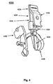
- FIG. 4 is a perspective view of an exemplary embodiment of system 4000.
- FIG. 5 is a perspective view of an exemplary embodiment of system 5000.
- apparatus an appliance or device for a particular purpose
- armature latch - a moveable component of a circuit breaker that releasably fastens and/or holds the operating mechanism of the circuit breaker.
- bi-metal element - a component adapted to be located in the conducting path of the circuit breaker, and adapted to, in response to the flow therethrough of a current of a predetermined approximate amplitude for a predetermined approximate time, generate heat, deflect in response to the heat, and thereby cause the circuit breaker to trip.
- central - situated at, in, or near the center of a length.
- circuit breaker - a device adapted to automatically open, and manually close, an alternating current electrical circuit.
- contact arm - a member comprising one of a pair of electrical contacts engageable to close a circuit.
- coupleable - capable of being joined, connected, and/or linked together.
- device - a machine, manufacture, and/or collection thereof.
- electric circuit - a system of electrically-connected electrical devices, the system providing a path for electrical energy to flow, i.e., a current path.
- handle - a manually operable lever for setting and/or resetting a position and/or status of a circuit breaker.
- line - a geometric figure formed by a point moving along a fixed direction and the reverse direction.
- load bus an electrically-conductive component of a circuit breaker located electrically downstream from the operating mechanism.
- magnetic element - a component adapted to be located in and/or adjacent the conducting path of the circuit breaker, and adapted to, in response to a current of a predetermined approximate amplitude for a predetermined approximate time, generate a magnetic field sufficient to substantially move an armature latch and/or a contact arm, thereby causing the circuit breaker to trip.
- method - a process, procedure, and/or collection of related activities for accomplishing something.
- molded case - an enclosure created by forming a molten thermoplastic.
- operating mechanism a portion of a circuit breaker that comprises pivoting member moveable between an ON position, an OFF position and a TRIPPED position to selectively engage and disengage operating contacts of the circuit breaker.
- system - a collection of mechanisms, devices, data, and/or instructions, the collection designed to perform one or more specific functions.
- zone - an area and/or region.
- a general function of a circuit breaker can be to electrically engage and disengage a selected circuit from an electrical power supply. This function can occur by engaging and disengaging a pair of operating contacts for each phase of the circuit breaker.
- the circuit breaker can provide protection against persistent overcurrent conditions and/or against very high currents produced by short circuits.
- One of each pair of the operating contacts can be supported by a pivoting contact arm while the other operating contact can be substantially stationary.
- the contact arm can be pivoted by an operating mechanism such that the movable contact supported by the contact arm can be engaged and disengaged from the stationary contact.
- the operating mechanism for the circuit breaker can disengage the operating contacts: the circuit breaker operating handle can be used to activate the operating mechanism; or a tripping mechanism, responsive to, for example, unacceptable levels of current carried by the circuit breaker, can be used to activate the operating mechanism.
- the operating handle can be coupled to the operating mechanism such that when the tripping mechanism activates the operating mechanism to separate the contacts, the operating handle moves to a fault or tripped position.
- the circuit breaker operating handle can be used to activate the operating mechanism such that the movable contact(s) engage the stationary contact(s).
- a motor coupled to the circuit breaker operating handle can also be used to engage or disengage the operating contacts. The motor can be remotely operated.
- a typical residential circuit breaker can have a continuous current rating ranging from as low as 5 amps to as high as 50 amps.
- a typical industrial circuit breaker can have a continuous current rating ranging from as low as 15 amps to as high as 160 amps.
- the tripping mechanism for the breaker can comprise a thermal overload release and a magnetic short circuit release.
- the thermal overload release can operate by means of a bi-metalic element, in which current flowing through the conducting path of a circuit breaker can generate heat in the bi-metal element, which can cause the bi-metal to deflect and trip the breaker.
- the heat generated in the bi-metal is typically a function of the amount of current flowing through the bi-metal as well as the period of time that current is flowing.
- the bi-metal cross-section and related elements can be specifically selected for such current range resulting in a number of different circuit breakers for each current range.
- the armature spring force can be varied, by an adjustment or by changing springs, to change the resisting force on the armature, which can change the current required to trip the breaker.
- the cross section of the steel in either the yoke, armature, or both can be adjusted to increase or decrease the amount of magnetic flux created by the short circuit current.
- FIG. 1 is a perspective view of an exemplary embodiment of an alternating current circuit breaker 1000 in a TRIPPED position.
- Circuit breaker 1000 can be thermally and/or electro-magnetically actuated and/or tripped.
- Circuit breaker 1000 can comprise a molded case and/or a body 1100 that can substantially contain and or surround most of the components of circuit breaker 1000.
- a handle 1200 Via its position with respect to body 1100, a handle 1200 can visually indicate a status of circuit breaker 1000, such as ON, TRIPPED, and/or OFF, etc.
- Handle 1200 can be moved into the TRIPPED position automatically by operation of various components of circuit breaker 1000.
- Handle 1200 can be moved into the ON, TRIPPED, and OFF positions manually.
- Circuit breaker 1000 can comprise a ground fault reset test button 1300, the manual actuation of which can trip circuit breaker 1000, an electronic trip device (not shown), and/or handle 1200 from an ON position to a TRIPPED position.
- handle 1200 can be moved from the TRIPPED position to the OFF position, and then to the ON position.
- FIGS. 2 and 3 are section views of an exemplary embodiment of circuit breaker 1000 taken along line A-A of FIG. 1 . Shown offset from circuit breaker 1000 in FIG. 3 is the general orientation of its XYZ coordinate system.
- a trip mechanism 1400 which can comprise an electro-magnetic element 1500 that can be magnetically, electrically, and/or mechanically coupled to a load bus 2100.
- Magnetic element 1500 can at least partially surround and/or be positioned substantially adjacent to a central zone of an elongated substantially planar bi-metal element 1600, which can also be electrically connected to load bus 2100 at location 2120.
- bi-metal element 1600 can comprise a proximal end zone 1620, a central zone 1640, and a distal end zone 1660.
- distal end zone 1660 can be thinner, as measured along the X coordinate axis, than proximal end zone 1620 and central zone 1640.
- distal end zone 1660 of bi-metal element 1600 can mechanically engage an armature latch 1700 (not shown in FIG. 3 ) that is adapted to trip an operating mechanism 1800 of circuit breaker 1000.
- a flexible conductor 1900 (not shown in FIG. 3 ) can electrically connect a contact arm 2000 to a location within central zone 1640 of bi-metal element 1600 and between electromagnetic element 1500 and distal end zone 1660 of bi-metal element 1600.
- FIG. 4 is a perspective view of an exemplary embodiment of system 4000, which can comprise a load bus 4100, which can be mechanically and/or electrically connected to a proximal end 4220 of a bi-metal element 4200.
- Load bus 4100 can be magnetically, electrically, and/or mechanically coupled to an electromagnetic element 4300, which can at least partially surround and/or be positioned substantially adjacent to a central zone 4240 of bi-metal element 4200.
- a flexible conductor 4400 can electrically connect a contact arm 4500 to a location within central zone 4240 of bi-metal element 4200 and between electromagnetic element 4300 and distal end zone 4260 of bi-metal element 4200. Note that distal end zone 4260 can be located substantially outside of a current path that connects load bus 4100 through bi-metal element 4200 and to flexible conductor 4400.
- FIG. 5 is a perspective view of an exemplary embodiment of system 5000, which can comprise a pair of substantially identical bi-metal elements 5100, 5200 that can be formed from a single bar 5300.
- Bi-metal element 5100 can define a central zone 5140 and an end zone 5160.
- Bi-metal element 5200 can define a central zone 5240 and an end zone 5260. Shown offset from bar 5300 is the general orientation of its XYZ coordinate system. Note that:
- the configuration of the end zones 5160 and 5260 and/or bi-metal elements 5100 and 5200 on bar 5300 can allow for:
Landscapes
- Physics & Mathematics (AREA)
- Electromagnetism (AREA)
- Engineering & Computer Science (AREA)
- Power Engineering (AREA)
- Breakers (AREA)
Claims (8)
- Vorrichtung, die eine Lastschiene (2100), eine Ankerklinke (1700) und einen Auslösemechanismus (1400) umfasst, wobei der Auslösemechanismus so ausgelegt ist, dass er mit einem Betätigungsmechanismus eines Wechselstrom-Leistungsschalters interagiert, und Folgendes umfasst:ein längliches, im Wesentlichen planares Bimetallelement (1600), das sich durch eine Länge und eine Breite kennzeichnen lässt, wobei das Bimetallelement längs in einen ersten Endbereich, einen mittleren Bereich und einen zweiten Endbereich untergliedert ist, die Lastschiene an den ersten Bereich gekoppelt ist, der zweite Endbereich eine Breite von maximal 60 Prozent einer Breite des mittleren Bereiches aufweist und so ausgelegt ist, dass er mit der Ankerklinke interagiert, die so ausgelegt ist, dass sie einen Betätigungsmechanismus des Leistungsschalters auslöst, undein elektromagnetisches Element (1500), das an die Lastschiene gekoppelt und im Wesentlichen neben dem mittleren Bereich des Bimetallelements positioniert ist, wobei die Vorrichtung ferner einen Kontaktarm (2000) umfasst, der elektrisch an das Bimetallelement gekoppelt ist, und einen flexiblen Leiter (1900), der den Kontaktarm und das Bimetallelement koppelt,dadurch gekennzeichnet, dass der Leiter (1900) an einer Stelle (2120) in dem mittleren Bereich (1640) des Bimetallelements (1600) sowie zwischen dem elektromagnetischen Element (1500) und dem zweiten Endbereich (1660) mit dem Bimetallelement verbunden ist, und wobei das magnetische Element (1500) den mittleren Bereich (1640) zumindest teilweise umgibt.
- Vorrichtung nach Anspruch 1, bei der es sich bei dem Leistungsschalter (1000) um einen Leistungsschalter mit Kunststoffgehäuse handelt.
- Vorrichtung nach Anspruch 1, bei der der zweite Endbereich (1660) nicht symmetrisch um eine Linie liegt, die dadurch definiert ist, dass sie eine Breite des mittleren Bereiches (1640) des Bimetallelements (1600) zweiteilt und parallel zu einer Länge des Bimetallelements verläuft.
- Vorrichtung nach Anspruch 1, bei der der zweite Endbereich (1660) im Wesentlichen auf einer Seite einer Linie liegt, die dadurch definiert ist, dass sie eine Breite des mittleren Bereiches (1640) des Bimetallelements (1600) zweiteilt und parallel zu einer Länge des Bimetallelements verläuft.
- Vorrichtung nach Anspruch 1, bei der eine Breite des ersten Endbereiches (1620) etwa einer Breite des mittleren Bereiches (1640) entspricht.
- Vorrichtung nach Anspruch 1, bei der der zweite Endbereich (1660) im Wesentlichen außerhalb eines Stromwegs des Bimetallelements (1600) liegt.
- Vorrichtung nach Anspruch 1, bei der das magnetische Element (1500) mit dem mittleren Bereich (1640) verbunden ist.
- Vorrichtung nach Anspruch 1, bei der der Auslösemechanismus (1400) so ausgelegt ist, dass er elektromagnetisch und thermisch betätigt wird.
Applications Claiming Priority (3)
| Application Number | Priority Date | Filing Date | Title |
|---|---|---|---|
| US59855204P | 2004-08-03 | 2004-08-03 | |
| US11/194,808 US7391289B2 (en) | 2004-08-03 | 2005-08-01 | Systems, methods, and device for actuating a circuit breaker |
| PCT/US2005/027206 WO2006017426A1 (en) | 2004-08-03 | 2005-08-02 | Systems, methods, and device for actuating a circuit breaker |
Publications (2)
| Publication Number | Publication Date |
|---|---|
| EP1782447A1 EP1782447A1 (de) | 2007-05-09 |
| EP1782447B1 true EP1782447B1 (de) | 2010-10-27 |
Family
ID=35756853
Family Applications (1)
| Application Number | Title | Priority Date | Filing Date |
|---|---|---|---|
| EP05777411A Expired - Lifetime EP1782447B1 (de) | 2004-08-03 | 2005-08-02 | Systeme, verfahren und einrichtung zur betätigung eines unterbrecherschalters |
Country Status (8)
| Country | Link |
|---|---|
| US (1) | US7391289B2 (de) |
| EP (1) | EP1782447B1 (de) |
| KR (1) | KR100854400B1 (de) |
| CN (1) | CN101036211B (de) |
| CA (1) | CA2575807A1 (de) |
| DE (1) | DE602005024410D1 (de) |
| MX (1) | MX2007001413A (de) |
| WO (1) | WO2006017426A1 (de) |
Cited By (1)
| Publication number | Priority date | Publication date | Assignee | Title |
|---|---|---|---|---|
| CN102760618A (zh) * | 2011-04-26 | 2012-10-31 | 西门子公司 | 断路器的脱扣机构及其断路器 |
Families Citing this family (15)
| Publication number | Priority date | Publication date | Assignee | Title |
|---|---|---|---|---|
| US7518482B2 (en) * | 2006-10-10 | 2009-04-14 | Dennis William Fleege | Trip unit having a plurality of stacked bimetal elements |
| US7397333B2 (en) * | 2006-10-18 | 2008-07-08 | Square D Company | Trip unit having bimetal element located outside the yoke |
| KR101096988B1 (ko) * | 2008-12-31 | 2011-12-20 | 엘에스산전 주식회사 | 트립 장치 |
| US8164018B2 (en) | 2009-03-23 | 2012-04-24 | Siemens Industry, Inc. | Circuit breaker arc chambers and methods for operating same |
| US9349559B2 (en) * | 2009-03-23 | 2016-05-24 | Siemens Industry, Inc. | Low-profile electronic circuit breakers, breaker tripping mechanisms, and systems and methods of using same |
| WO2010139113A1 (zh) * | 2009-06-03 | 2010-12-09 | Abb瑞士有限公司 | 模块化低压开关器 |
| US8563882B2 (en) * | 2010-10-12 | 2013-10-22 | Siemens Industry, Inc. | Electronic circuit breaker having a locking and unlocking mechanism and methods of operating same |
| US8830026B2 (en) * | 2010-12-30 | 2014-09-09 | General Electric Company | Shape memory alloy actuated circuit breaker |
| US8476992B2 (en) | 2011-10-07 | 2013-07-02 | Siemens Industry, Inc. | Circuit breaker having an unlocking mechanism and methods of operating same |
| AT512262B1 (de) * | 2011-12-09 | 2016-08-15 | Eaton Ind Austria Gmbh | Verfahren zum justieren einer auslöseeinheit für einen schutzschalter |
| US9406474B2 (en) * | 2012-02-23 | 2016-08-02 | Siemens Aktiengesellschaft | Circuit breaker heaters and translational magnetic systems |
| FR3007573B1 (fr) | 2013-06-20 | 2015-07-17 | Schneider Electric Ind Sas | Declencheur et procede de fabrication d'un tel declencheur |
| CN106783417B (zh) | 2015-11-23 | 2020-08-11 | 森萨塔科技公司 | 断路器 |
| USD777117S1 (en) * | 2016-04-27 | 2017-01-24 | Sensata Technologies, Inc. | Switch assembly with escutcheon |
| US10847333B2 (en) * | 2018-09-17 | 2020-11-24 | Siemends Industry, Inc. | Circuit breakers including dual triggering devices and methods of operating same |
Citations (2)
| Publication number | Priority date | Publication date | Assignee | Title |
|---|---|---|---|---|
| US3904998A (en) * | 1974-06-05 | 1975-09-09 | Caribe Circuit Breaker Co Inc | Circuit breaker |
| US3909764A (en) * | 1974-06-05 | 1975-09-30 | Caribe Circuit Breaker Co Inc | Electric circuit breaker |
Family Cites Families (24)
| Publication number | Priority date | Publication date | Assignee | Title |
|---|---|---|---|---|
| US2320437A (en) * | 1941-05-07 | 1943-06-01 | Westinghouse Electric & Mfg Co | Circuit breaker |
| US2689893A (en) * | 1952-12-16 | 1954-09-21 | Ite Circuit Breaker Ltd | Thermal magnetic trip device |
| US3110786A (en) | 1959-11-03 | 1963-11-12 | Westinghouse Electric Corp | Electromagnetic thermal current circuit breaker |
| US3244837A (en) * | 1962-12-17 | 1966-04-05 | Ite Circuit Breaker Ltd | Heating means for bimetal trip element |
| US4231006A (en) * | 1979-03-26 | 1980-10-28 | Sylvania Circuit Breaker Corporation | Circuit breaker having a thermally responsive latching member |
| US4719438A (en) * | 1986-09-30 | 1988-01-12 | Westinghouse Electric Corp. | Circuit breaker with fast trip unit |
| US4868529A (en) * | 1988-08-24 | 1989-09-19 | Siemens Energy & Automation, Inc. | Circuit breaker armature latch with control leg |
| US5214402A (en) * | 1991-12-23 | 1993-05-25 | North American Philips Corporation | Trip link latch and interpole link for a circuit breaker |
| DE4142965A1 (de) | 1991-12-24 | 1993-07-01 | Abb Patent Gmbh | Thermischer ausloeser |
| US5373272A (en) * | 1994-01-13 | 1994-12-13 | Square D Company | High current capacity blade for a circuit breaker |
| US5430419A (en) * | 1994-01-13 | 1995-07-04 | Square D | Double break circuit breaker having improved secondary section |
| US5680081A (en) * | 1994-01-13 | 1997-10-21 | Square D Company | Circuit breaker having double break mechanism |
| US5510759A (en) * | 1994-06-23 | 1996-04-23 | Eaton Corporation | Miniature circuit breaker with ground fault electronics supported by stiff conductors for easy assembly |
| US5453723A (en) * | 1994-06-23 | 1995-09-26 | Eaton Corporation | Two-pole compartmentalized ground fault miniature circuit breaker with increased current rating |
| US5483211A (en) * | 1994-06-23 | 1996-01-09 | Eaton Corporation | Two-pole compartmentalized ground fault miniature circuit breaker with a single central electronics compartment |
| FR2722331B1 (fr) | 1994-07-08 | 1996-09-27 | Legrand Sa | Sous-ensemble thermique pour disjoncteur |
| US5608367A (en) * | 1995-11-30 | 1997-03-04 | Eaton Corporation | Molded case circuit breaker with interchangeable trip unit having bimetal assembly which registers with permanent heater transformer airgap |
| US5565827A (en) * | 1995-12-04 | 1996-10-15 | Eaton Corporation | Circuit breaker with current conducting blow open latch |
| US5872495A (en) | 1997-12-10 | 1999-02-16 | Siemens Energy & Automation, Inc. | Variable thermal and magnetic structure for a circuitbreaker trip unit |
| US6747534B1 (en) * | 1999-08-18 | 2004-06-08 | Eaton Corporation | Circuit breaker with dial indicator for magnetic trip level adjustment |
| EP1098337A3 (de) * | 1999-11-05 | 2002-08-07 | Siemens Energy & Automation, Inc. | Signalzusatzmodul für Leistungsschalter mit gegossenem Gehäuse |
| US6597266B1 (en) * | 1999-11-05 | 2003-07-22 | Siemens Energy & Automation, Inc. | External actuator interlock mechanism for circuit breaker |
| US6181226B1 (en) * | 1999-11-05 | 2001-01-30 | Siemens Energy & Automation, Inc. | Bi-metal trip unit for a molded case circuit breaker |
| US6255925B1 (en) * | 2000-02-18 | 2001-07-03 | Siemens Energy & Automation, Inc. | Thermal-magnetic trip unit with adjustable magnetic tripping |
-
2005
- 2005-08-01 US US11/194,808 patent/US7391289B2/en not_active Expired - Fee Related
- 2005-08-02 EP EP05777411A patent/EP1782447B1/de not_active Expired - Lifetime
- 2005-08-02 CA CA002575807A patent/CA2575807A1/en not_active Abandoned
- 2005-08-02 DE DE602005024410T patent/DE602005024410D1/de not_active Expired - Lifetime
- 2005-08-02 WO PCT/US2005/027206 patent/WO2006017426A1/en not_active Ceased
- 2005-08-02 MX MX2007001413A patent/MX2007001413A/es active IP Right Grant
- 2005-08-02 KR KR1020077003957A patent/KR100854400B1/ko not_active Expired - Fee Related
- 2005-08-02 CN CN2005800337029A patent/CN101036211B/zh not_active Expired - Fee Related
Patent Citations (2)
| Publication number | Priority date | Publication date | Assignee | Title |
|---|---|---|---|---|
| US3904998A (en) * | 1974-06-05 | 1975-09-09 | Caribe Circuit Breaker Co Inc | Circuit breaker |
| US3909764A (en) * | 1974-06-05 | 1975-09-30 | Caribe Circuit Breaker Co Inc | Electric circuit breaker |
Cited By (2)
| Publication number | Priority date | Publication date | Assignee | Title |
|---|---|---|---|---|
| CN102760618A (zh) * | 2011-04-26 | 2012-10-31 | 西门子公司 | 断路器的脱扣机构及其断路器 |
| CN102760618B (zh) * | 2011-04-26 | 2015-04-08 | 西门子公司 | 断路器的脱扣机构及其断路器 |
Also Published As
| Publication number | Publication date |
|---|---|
| KR20070038156A (ko) | 2007-04-09 |
| CN101036211A (zh) | 2007-09-12 |
| DE602005024410D1 (de) | 2010-12-09 |
| CN101036211B (zh) | 2010-05-05 |
| US7391289B2 (en) | 2008-06-24 |
| KR100854400B1 (ko) | 2008-08-26 |
| US20060028307A1 (en) | 2006-02-09 |
| CA2575807A1 (en) | 2006-02-16 |
| MX2007001413A (es) | 2007-04-10 |
| WO2006017426A1 (en) | 2006-02-16 |
| EP1782447A1 (de) | 2007-05-09 |
Similar Documents
| Publication | Publication Date | Title |
|---|---|---|
| EP1782447B1 (de) | Systeme, verfahren und einrichtung zur betätigung eines unterbrecherschalters | |
| US9601295B2 (en) | Breaker tripping mechanisms, circuit breakers, systems, and methods of using same | |
| CN102568955B (zh) | 形状记忆合金促动的断路器 | |
| EP2837013B1 (de) | Schutzschalter mit niedriger auslösungsebene sowie auslösungseinheiten und verfahren | |
| US7843291B2 (en) | Integrated maglatch accessory | |
| EP1098337A2 (de) | Signalzusatzmodul für Leistungsschalter mit gegossenem Gehäuse | |
| US6181226B1 (en) | Bi-metal trip unit for a molded case circuit breaker | |
| US9899160B2 (en) | Low-profile electronic circuit breakers, systems, and methods | |
| GB2359928A (en) | Connector strap for a rotary contact circuit breaker | |
| EP1131836B1 (de) | Klappankersystem für einen schutzschalter | |
| CA2899773C (en) | Bimetal and magnetic armature providing an arc splatter resistant offset therebetween, and circuit breaker including the same | |
| US6617533B1 (en) | Interlock for a circuit breaker | |
| WO2013126061A1 (en) | Circuit breaker heaters and translational magnetic systems | |
| EP3559974B1 (de) | Elektrische schaltvorrichtung und thermische auslösungsanordnung dafür | |
| EP2472549B1 (de) | Bimetallanordnung für Schutzschalter | |
| US8149075B2 (en) | Plastic cradle | |
| US6972649B1 (en) | Method and apparatus for shielding and armature from a magnetic flux | |
| NZ202137A (en) | Ac/dc circuit breaker:thermal trip heat paths | |
| MXPA01005131A (en) | Clapper armature system for a circuit breaker |
Legal Events
| Date | Code | Title | Description |
|---|---|---|---|
| PUAI | Public reference made under article 153(3) epc to a published international application that has entered the european phase |
Free format text: ORIGINAL CODE: 0009012 |
|
| 17P | Request for examination filed |
Effective date: 20070129 |
|
| AK | Designated contracting states |
Kind code of ref document: A1 Designated state(s): DE FR GB IT |
|
| 17Q | First examination report despatched |
Effective date: 20070518 |
|
| DAX | Request for extension of the european patent (deleted) | ||
| RBV | Designated contracting states (corrected) |
Designated state(s): DE FR GB IT |
|
| GRAP | Despatch of communication of intention to grant a patent |
Free format text: ORIGINAL CODE: EPIDOSNIGR1 |
|
| RAP1 | Party data changed (applicant data changed or rights of an application transferred) |
Owner name: SIEMENS INDUSTRY, INC. |
|
| GRAS | Grant fee paid |
Free format text: ORIGINAL CODE: EPIDOSNIGR3 |
|
| GRAA | (expected) grant |
Free format text: ORIGINAL CODE: 0009210 |
|
| AK | Designated contracting states |
Kind code of ref document: B1 Designated state(s): DE FR GB IT |
|
| REG | Reference to a national code |
Ref country code: GB Ref legal event code: FG4D |
|
| REF | Corresponds to: |
Ref document number: 602005024410 Country of ref document: DE Date of ref document: 20101209 Kind code of ref document: P |
|
| PLBE | No opposition filed within time limit |
Free format text: ORIGINAL CODE: 0009261 |
|
| STAA | Information on the status of an ep patent application or granted ep patent |
Free format text: STATUS: NO OPPOSITION FILED WITHIN TIME LIMIT |
|
| 26N | No opposition filed |
Effective date: 20110728 |
|
| REG | Reference to a national code |
Ref country code: DE Ref legal event code: R097 Ref document number: 602005024410 Country of ref document: DE Effective date: 20110728 |
|
| GBPC | Gb: european patent ceased through non-payment of renewal fee |
Effective date: 20110802 |
|
| REG | Reference to a national code |
Ref country code: FR Ref legal event code: ST Effective date: 20120430 |
|
| PG25 | Lapsed in a contracting state [announced via postgrant information from national office to epo] |
Ref country code: IT Free format text: LAPSE BECAUSE OF NON-PAYMENT OF DUE FEES Effective date: 20110802 |
|
| REG | Reference to a national code |
Ref country code: DE Ref legal event code: R119 Ref document number: 602005024410 Country of ref document: DE Effective date: 20120301 |
|
| PG25 | Lapsed in a contracting state [announced via postgrant information from national office to epo] |
Ref country code: FR Free format text: LAPSE BECAUSE OF NON-PAYMENT OF DUE FEES Effective date: 20110831 Ref country code: GB Free format text: LAPSE BECAUSE OF NON-PAYMENT OF DUE FEES Effective date: 20110802 |
|
| PG25 | Lapsed in a contracting state [announced via postgrant information from national office to epo] |
Ref country code: DE Free format text: LAPSE BECAUSE OF NON-PAYMENT OF DUE FEES Effective date: 20120301 |