EP1783408A1 - Dispositif déviateur ou combinateur pour des installations hydrauliques - Google Patents
Dispositif déviateur ou combinateur pour des installations hydrauliques Download PDFInfo
- Publication number
- EP1783408A1 EP1783408A1 EP06076864A EP06076864A EP1783408A1 EP 1783408 A1 EP1783408 A1 EP 1783408A1 EP 06076864 A EP06076864 A EP 06076864A EP 06076864 A EP06076864 A EP 06076864A EP 1783408 A1 EP1783408 A1 EP 1783408A1
- Authority
- EP
- European Patent Office
- Prior art keywords
- chamber
- hydraulic installations
- rotor
- tubular closure
- openings
- Prior art date
- Legal status (The legal status is an assumption and is not a legal conclusion. Google has not performed a legal analysis and makes no representation as to the accuracy of the status listed.)
- Withdrawn
Links
- XLYOFNOQVPJJNP-UHFFFAOYSA-N water Substances O XLYOFNOQVPJJNP-UHFFFAOYSA-N 0.000 title description 4
- 238000009434 installation Methods 0.000 claims description 13
- 238000004891 communication Methods 0.000 claims description 12
- 230000036316 preload Effects 0.000 claims description 6
- 230000001681 protective effect Effects 0.000 abstract 1
- 238000012856 packing Methods 0.000 description 5
- 238000006073 displacement reaction Methods 0.000 description 4
- 230000008901 benefit Effects 0.000 description 3
- 235000021183 entrée Nutrition 0.000 description 3
- 238000010276 construction Methods 0.000 description 2
- 238000007789 sealing Methods 0.000 description 2
- 230000002349 favourable effect Effects 0.000 description 1
- 235000013305 food Nutrition 0.000 description 1
- 238000000034 method Methods 0.000 description 1
- 238000012986 modification Methods 0.000 description 1
- 230000004048 modification Effects 0.000 description 1
- 210000000056 organ Anatomy 0.000 description 1
- 230000002093 peripheral effect Effects 0.000 description 1
Images


Classifications
-
- F—MECHANICAL ENGINEERING; LIGHTING; HEATING; WEAPONS; BLASTING
- F16—ENGINEERING ELEMENTS AND UNITS; GENERAL MEASURES FOR PRODUCING AND MAINTAINING EFFECTIVE FUNCTIONING OF MACHINES OR INSTALLATIONS; THERMAL INSULATION IN GENERAL
- F16K—VALVES; TAPS; COCKS; ACTUATING-FLOATS; DEVICES FOR VENTING OR AERATING
- F16K11/00—Multiple-way valves, e.g. mixing valves; Pipe fittings incorporating such valves
- F16K11/02—Multiple-way valves, e.g. mixing valves; Pipe fittings incorporating such valves with all movable sealing faces moving as one unit
- F16K11/06—Multiple-way valves, e.g. mixing valves; Pipe fittings incorporating such valves with all movable sealing faces moving as one unit comprising only sliding valves, i.e. sliding closure elements
- F16K11/072—Multiple-way valves, e.g. mixing valves; Pipe fittings incorporating such valves with all movable sealing faces moving as one unit comprising only sliding valves, i.e. sliding closure elements with pivoted closure members
- F16K11/074—Multiple-way valves, e.g. mixing valves; Pipe fittings incorporating such valves with all movable sealing faces moving as one unit comprising only sliding valves, i.e. sliding closure elements with pivoted closure members with flat sealing faces
- F16K11/0743—Multiple-way valves, e.g. mixing valves; Pipe fittings incorporating such valves with all movable sealing faces moving as one unit comprising only sliding valves, i.e. sliding closure elements with pivoted closure members with flat sealing faces with both the supply and the discharge passages being on one side of the closure plates
Definitions
- the present invention relates to a hydraulic device which can be embodied in the form of a deflector or / and a combiner.
- a deflector for hydraulic installations is a device which is intended to receive a supply inlet, coming from a duct or valve possibly mixing, and which is provided with an operating member made available to a user, which actuator authorizes the selective connection of said supply input to one or another of two or more flow outputs.
- a combiner differs from a deflator in that it must also allow the selective connection of the power input simultaneously to two or more of a plurality of flow outputs.
- a chamber receives the connections of the supply inlet and the flow outlets, and comprises a rotor provided with an operating member; in the rotor is made at least one passage which is sealingly connected to the supply inlet and which, with its displacement, can be connected in a sealed manner to the flow outputs that the user wants to connect to the input of 'food.
- the rotor must be provided with one or more movable seals, intended to cooperate with the supply inlet and with at least one of the flow outlets, and these seals must be subjected to a mechanical pressure sufficient to establish tightness even in the presence of the highest hydraulic pressure that can be expected that will prove on special occasions, while in the normal operation of the device the hydraulic pressure is much lower.
- the seals are unnecessarily subjected to high wear, and in addition the frictional resistance they oppose to the operation of the rotor is unnecessarily high. The consequences are a reduction in the useful life of the device and an increase in the force that the user must apply for the maneuver.
- the passage made in the rotor can not have a large section, and it must have a relatively complex conformation, so that this passage opposes a considerable resistance to the flow, and the maximum flow rate admitted by the device is relatively small compared to the dimensions of the device.
- the object of the present invention is to overcome the disadvantages of known devices.
- an object of the invention is to allow to proportion at any time the mechanical pressure applied to the seals at the hydraulic pressure actually present. It is also an object of the invention to reduce seal wear and the force required to operate the device. Another object is to reduce the number of seals subjected to displacement which the device must be provided, as well as to simplify the conformation. A particular goal is to allow a high throughput relative to the dimensions of the device. Yet another object of the invention is to achieve the stated technical goals without increasing or even reducing the cost of the device.
- the device according to the invention is of the type which comprises a body, in said body a chamber in which a feed inlet opens, said chamber comprising a flat surface in which openings connected to flow outlets are formed, and said chamber comprising a rotor whose axis of rotation is perpendicular to said flat surface of the chamber, this rotor being provided with an operating member, and this device is characterized in that said feed inlet opens freely in said chamber, and said rotor comprises one or more tubular shutter members, each of which comprises a piston-shaped seal applied against said flat surface of the chamber and cooperating with said openings of the flow outlets to close them, the cavity of said organ tubular obturator being in communication with said chamber.
- a resilient pre-load member may be disposed in each tubular closure member to apply to the corresponding piston seal an auxiliary mechanical pressure directed toward said flat surface of the chamber.
- the device can be configured as a deflector having two or more flow outlets, or as a combiner capable of performing any desired combination of flow output connections with the power input.
- each piston seal of a tubular closure member is pushed against the surface in which the openings connected to the flow outlets are formed by the hydraulic pressure present in the chamber, which communicates permanently with the feed inlet and with which communicate the tubular closure members. Therefore, the mechanical pressure applied to these linings is always proportioned to the hydraulic pressure to which the seal must resist.
- a resilient pre-load member When a resilient pre-load member is provided, it only has the auxiliary function of sealing even in the presence of a very low hydraulic pressure, and the force it exerts can be very small. As a result, with a high degree of operational safety, a reduction in the wear of the packings as well as the force required for the operation of the device.
- Another advantage of the arrangement according to the invention is the reduction in the number of packings subjected to displacement. Indeed, only movable liners intended to cooperate with the outlet openings are required, while the supply inlet to the chamber is free. In addition, this input, which is not intended to cooperate with the rotor, may be arranged relative to the chamber in any position considered favorable.
- the resistance opposed to the flow by the device is extremely reduced because either the feed inlet, or the flow outlets that are not closed by the tubular closure members, open directly and freely in the chamber, which forms a direct communication of the entrance to the exit, without the flow having to traverse a relatively narrowed passage.
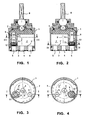
- the number 1 designates the body of the device, which in these examples is configured as a cartridge, but of course can be configured in any way.
- a chamber 2 which is limited at the bottom (according to the drawings) by a bottom 3 which has a feed inlet opening 4 and two flow outlet openings 5 and 6, all opening on the upper flat surface 3 'of the bottom 3, which constitutes a flat surface of the chamber 2.
- the bottom 3 may constitute a separate element applied to the body 1, as shown, or it may be made in one piece with the body 1.
- a rotor 7 which is rotatably connected to a control means, such as a rod 8 for receiving a handle (not shown) or other operating means made available to a user.
- the rotor 7 can rotate around a perpendicular axis of rotation 0 of the flat surface 3 'of the bottom 3, on which the openings 4, 5 and 6 open.
- the rotor 7 comprises a tubular closure member 9 whose cavity 10 communicates through openings 11 with the chamber 2.
- a seal 12 having the form of a piston, whose working surface bears against the flat surface 3 'of the bottom 3.
- An elastic member, such as a spring 13 can be arranged to push the lining 12 against the bottom 3.
- this function can also be fulfilled by the inherent elasticity of the lining 12 and / or by appropriate conformations of the lining and the seat formed for the lining in the cavity 10 of the tubular closure member 9.
- the operation of the device is as follows.
- the rotor 7 is carried in a position like that according to FIGS. 1 and 3, in which the tubular closure member 9 is arranged with its seal 12 in correspondence of the outlet opening 5, this outlet opening 5 is closed and can not be fed.
- the outlet opening 6 is in free communication with the inlet opening 4 through the chamber 2, and when water is fed through the inlet opening 4, it flows to through the chamber 2 and the outlet opening 6 without encountering any appreciable resistance.
- the device can therefore allow a large flow, even if it can have small dimensions.
- the device thus behaves like a deflector between the two outlet apertures 5 and 6.
- Suitable conformations of the rotor 7 and the body 1 can delineate in a known manner the rotation allowed to the rotor 7, so as to facilitate the user's maneuvering. , by precisely determining the two working positions of the deviator. It should be noted that this diverter requires a single liner subject to displacement, and that this lining is of particularly economical construction for its shape.
- the chamber 2 which freely communicates with the inlet opening 4, is subjected to the working hydraulic pressure, which through the openings 11 is transmitted to the cavity 10 of the tubular closure member 9, and therefore applies to the piston seal 12 by pushing it against the flat surface of the bottom 3. Therefore, the mechanical pressure exerted on the seal 12 is always proportioned to the hydraulic pressure against which it must be obtained. seal. In this way, an effective seal is always ensured, while at the same time avoiding unnecessary wear of the packing as well as the unnecessary increase of the friction and therefore of the force required for the operation of the deflector.
- the position relative to the chamber 2 in which the feed opening 4 is formed in the bottom 3 is not critical.
- This opening can be arranged in the position considered more suitable for reasons of construction and / or installation.
- this opening may be central as in Figures 3 and 4, or it may be peripheral as shown in Figure 5. In other cases, this opening could be practiced in the body 1 instead of in the background 3.
- FIG. 6-9 there is shown a device constituting a deviator with three outputs. Parts that correspond to the parts described with respect to the foregoing figures are designated by the same reference numerals.
- the outlet openings in the bottom 3 are in number of three: 5, 6 and 14, and the rotor 9, instead of presenting only a tubular closure member 9 with its cavity 10, the openings 11, the packing 12 and possibly the pre-load spring 13 is provided with two tubular closure members 9 'and 9 "with their cavities 10' and 10 ", the openings 11 'and 11", the gaskets 12' and 12 "and possibly the preloading springs 13 'and 13"
- Figures 10 to 12 show how the device according to the invention can be realized in the form of a combiner.
- the outlet openings in the bottom 3 are the same 5, 6 and 14 which are shown in Figures 7 to 9, but in this case the device is provided with three tubular closure members 9 °, 9 and 9 "with their cavities, the communication openings with the chamber of the device, the gaskets 12 °, 12 'and 12" and possibly pre-load springs.
- the gaskets 12 'and 12 "close two outlet openings and leave free only the outlet opening 14 which, therefore, communicates with the inlet opening of 4, when the device is carried in the position shown in FIG.
- the packings 12 'and 12 "close two outlet openings and leave it free only when the rotation of the rotor 7 is in the position shown in FIG. outlet opening 5 which, therefore, communicates with the feed inlet opening 4; the seal 12 ° remains still inactive.
- the seal 12 ° closes an outlet opening and leaves free the two outlet openings 5 and 14 which, therefore, communicate with the feed inlet opening 4; in this case, the two gaskets 12 'and 12 "remain inactive
- the device constitutes a combiner that allows selective feeding of only one of its three outlet openings, or any combination of two outlet openings. It will be readily understood that by appropriately selecting the number and arrangement of the outlet openings and the number and arrangement of the tubular closure members, a number of operating conditions known to be useful for a combiner can be realized.
- FIGS. 1 to 4 and 6 to 9 can function as combiners, even if with limited characteristics, if intermediate work positions are provided between the positions shown.
- FIG. 13 shows that, by giving a lining 12 '"an arcuate shape, this lining can perform the functions of two liners such as those 12' and 12" according to FIG. 7, or of three liners such as those 12 °, 12 'and 12 "according to FIG. 10.
- Such an arc-shaped lining may be supported by a single tubular closure member also having a corresponding arcuate section, or by two or more tubular closure members of circular cross-section (for example those according to Figure 6) supporting different points of the arcuate lining 12 "'.
Landscapes
- Engineering & Computer Science (AREA)
- General Engineering & Computer Science (AREA)
- Mechanical Engineering (AREA)
- Multiple-Way Valves (AREA)
Applications Claiming Priority (1)
| Application Number | Priority Date | Filing Date | Title |
|---|---|---|---|
| ITTO20050779 ITTO20050779A1 (it) | 2005-11-03 | 2005-11-03 | Dispositivo deviatore o combinatore per impianti idraulici |
Publications (1)
| Publication Number | Publication Date |
|---|---|
| EP1783408A1 true EP1783408A1 (fr) | 2007-05-09 |
Family
ID=37686127
Family Applications (1)
| Application Number | Title | Priority Date | Filing Date |
|---|---|---|---|
| EP06076864A Withdrawn EP1783408A1 (fr) | 2005-11-03 | 2006-10-11 | Dispositif déviateur ou combinateur pour des installations hydrauliques |
Country Status (3)
| Country | Link |
|---|---|
| EP (1) | EP1783408A1 (it) |
| IT (1) | ITTO20050779A1 (it) |
| WO (1) | WO2007051597A1 (it) |
Cited By (3)
| Publication number | Priority date | Publication date | Assignee | Title |
|---|---|---|---|---|
| WO2011088782A1 (zh) * | 2010-01-20 | 2011-07-28 | 厦门松霖科技有限公司 | 带插座三通阀 |
| CN106764042A (zh) * | 2017-01-21 | 2017-05-31 | 宁波惠荣电器有限公司 | 用于电热水龙头的阀件 |
| WO2018115713A1 (fr) | 2016-12-20 | 2018-06-28 | Zodiac Pool Care Europe | Vanne compacte multivoie de raccordement entre deux circuits de circulation de fluide |
Families Citing this family (1)
| Publication number | Priority date | Publication date | Assignee | Title |
|---|---|---|---|---|
| CN112302123B (zh) * | 2020-09-02 | 2022-05-31 | 厦门致杰智能科技有限公司 | 一种水路切换结构及切换方法 |
Citations (5)
| Publication number | Priority date | Publication date | Assignee | Title |
|---|---|---|---|---|
| US2428410A (en) * | 1943-07-30 | 1947-10-07 | Lee G Daniels | Rotary type multiport valve |
| LU38756A1 (it) * | 1959-06-04 | 1960-08-01 | ||
| GB1283197A (en) * | 1969-05-27 | 1972-07-26 | Gullick Dobson Ltd | Improvements in or relating to self-aligning or self-seating devices applicable, for example, to fluid-flow control valves |
| WO1991005191A1 (en) * | 1989-10-05 | 1991-04-18 | Masco Corporation | Cartridge for a single control lever mixing faucet with connecting pipes reinforced by elastic means |
| US6367504B1 (en) * | 1997-10-06 | 2002-04-09 | Masco Corporation Of Indiana | Multi-way stop or diverter valve |
-
2005
- 2005-11-03 IT ITTO20050779 patent/ITTO20050779A1/it unknown
-
2006
- 2006-10-11 EP EP06076864A patent/EP1783408A1/fr not_active Withdrawn
- 2006-10-31 WO PCT/EP2006/010479 patent/WO2007051597A1/de not_active Ceased
Patent Citations (5)
| Publication number | Priority date | Publication date | Assignee | Title |
|---|---|---|---|---|
| US2428410A (en) * | 1943-07-30 | 1947-10-07 | Lee G Daniels | Rotary type multiport valve |
| LU38756A1 (it) * | 1959-06-04 | 1960-08-01 | ||
| GB1283197A (en) * | 1969-05-27 | 1972-07-26 | Gullick Dobson Ltd | Improvements in or relating to self-aligning or self-seating devices applicable, for example, to fluid-flow control valves |
| WO1991005191A1 (en) * | 1989-10-05 | 1991-04-18 | Masco Corporation | Cartridge for a single control lever mixing faucet with connecting pipes reinforced by elastic means |
| US6367504B1 (en) * | 1997-10-06 | 2002-04-09 | Masco Corporation Of Indiana | Multi-way stop or diverter valve |
Cited By (4)
| Publication number | Priority date | Publication date | Assignee | Title |
|---|---|---|---|---|
| WO2011088782A1 (zh) * | 2010-01-20 | 2011-07-28 | 厦门松霖科技有限公司 | 带插座三通阀 |
| WO2018115713A1 (fr) | 2016-12-20 | 2018-06-28 | Zodiac Pool Care Europe | Vanne compacte multivoie de raccordement entre deux circuits de circulation de fluide |
| CN106764042A (zh) * | 2017-01-21 | 2017-05-31 | 宁波惠荣电器有限公司 | 用于电热水龙头的阀件 |
| CN106764042B (zh) * | 2017-01-21 | 2022-12-20 | 宁波惠荣电器有限公司 | 用于电热水龙头的阀件 |
Also Published As
| Publication number | Publication date |
|---|---|
| ITTO20050779A1 (it) | 2007-05-04 |
| WO2007051597A1 (de) | 2007-05-10 |
Similar Documents
| Publication | Publication Date | Title |
|---|---|---|
| EP0148480B1 (fr) | Vanne dont l'ouverture fonctionne a la depression | |
| EP0619003B1 (fr) | Cartouche avec plaques en materiau dur pour un robinet monocommande | |
| FR2480391A1 (fr) | Robinet a joints ignifuges | |
| FR2688857A1 (fr) | Vanne comportant un obturateur basculant et une membrane d'isolation. | |
| EP1433988B1 (fr) | Vanne de régulation | |
| FR2657138A1 (fr) | Partie de raccord rapide a organe de reduction de pression. | |
| FR2792988A1 (fr) | Cartouche de robinet mitigeur a limitation de temperature | |
| CH616732A5 (it) | ||
| FR2829217A1 (fr) | Dispositif permettant de controler la distribution d'un fluide | |
| EP1783408A1 (fr) | Dispositif déviateur ou combinateur pour des installations hydrauliques | |
| EP0952376A1 (fr) | Vanne à clapets et membrane gonflable | |
| FR3079879A1 (fr) | Vanne de decharge a ouverture regulee | |
| EP0418956A2 (fr) | Robinet mélangeur avec obturateur sphérique | |
| FR2727734A1 (fr) | Vannes de reglage a double debit | |
| EP1431639A1 (fr) | Vanne à actionneur intégré | |
| EP0942346B1 (fr) | Soupape à trois voies pour régulation de pression | |
| FR2847644A1 (fr) | Soupape a commande par solenoide | |
| EP3685080A1 (fr) | Vanne thermostatique pour véhicule automobile | |
| EP4305328A1 (fr) | Vanne de detente comportant un coulisseau mobile | |
| EP3537251B1 (fr) | Robinet mitigeur thermostatique | |
| FR2821128A1 (fr) | Distributeur pneumatique | |
| EP0029387A1 (fr) | Disconnecteur pour canalisation d'eau potable | |
| FR2944083A1 (fr) | Dispositif de controle de la circulation d'un fluide au niveau d'une ouverture et circuit comportant un tel dispositif. | |
| FR2887950A1 (fr) | Vanne sans siege, a obturateur coulissant pour la distribution du gaz | |
| FR2561345A1 (fr) | Vanne a plusieurs voies |
Legal Events
| Date | Code | Title | Description |
|---|---|---|---|
| PUAI | Public reference made under article 153(3) epc to a published international application that has entered the european phase |
Free format text: ORIGINAL CODE: 0009012 |
|
| AK | Designated contracting states |
Kind code of ref document: A1 Designated state(s): AT BE BG CH CY CZ DE DK EE ES FI FR GB GR HU IE IS IT LI LT LU LV MC NL PL PT RO SE SI SK TR |
|
| AX | Request for extension of the european patent |
Extension state: AL BA HR MK YU |
|
| STAA | Information on the status of an ep patent application or granted ep patent |
Free format text: STATUS: THE APPLICATION HAS BEEN WITHDRAWN |
|
| 18W | Application withdrawn |
Effective date: 20071109 |