EP1793609A2 - Method and system for managing multiview videos - Google Patents
Method and system for managing multiview videos Download PDFInfo
- Publication number
- EP1793609A2 EP1793609A2 EP06023909A EP06023909A EP1793609A2 EP 1793609 A2 EP1793609 A2 EP 1793609A2 EP 06023909 A EP06023909 A EP 06023909A EP 06023909 A EP06023909 A EP 06023909A EP 1793609 A2 EP1793609 A2 EP 1793609A2
- Authority
- EP
- European Patent Office
- Prior art keywords
- multiview
- reference pictures
- view
- reference picture
- temporal
- Prior art date
- Legal status (The legal status is an assumption and is not a legal conclusion. Google has not performed a legal analysis and makes no representation as to the accuracy of the status listed.)
- Granted
Links
Images





Classifications
-
- H—ELECTRICITY
- H04—ELECTRIC COMMUNICATION TECHNIQUE
- H04N—PICTORIAL COMMUNICATION, e.g. TELEVISION
- H04N19/00—Methods or arrangements for coding, decoding, compressing or decompressing digital video signals
- H04N19/60—Methods or arrangements for coding, decoding, compressing or decompressing digital video signals using transform coding
- H04N19/61—Methods or arrangements for coding, decoding, compressing or decompressing digital video signals using transform coding in combination with predictive coding
- H04N19/615—Methods or arrangements for coding, decoding, compressing or decompressing digital video signals using transform coding in combination with predictive coding using motion compensated temporal filtering [MCTF]
-
- H—ELECTRICITY
- H04—ELECTRIC COMMUNICATION TECHNIQUE
- H04N—PICTORIAL COMMUNICATION, e.g. TELEVISION
- H04N19/00—Methods or arrangements for coding, decoding, compressing or decompressing digital video signals
- H04N19/10—Methods or arrangements for coding, decoding, compressing or decompressing digital video signals using adaptive coding
- H04N19/102—Methods or arrangements for coding, decoding, compressing or decompressing digital video signals using adaptive coding characterised by the element, parameter or selection affected or controlled by the adaptive coding
- H04N19/103—Selection of coding mode or of prediction mode
-
- H—ELECTRICITY
- H04—ELECTRIC COMMUNICATION TECHNIQUE
- H04N—PICTORIAL COMMUNICATION, e.g. TELEVISION
- H04N19/00—Methods or arrangements for coding, decoding, compressing or decompressing digital video signals
- H04N19/10—Methods or arrangements for coding, decoding, compressing or decompressing digital video signals using adaptive coding
- H04N19/102—Methods or arrangements for coding, decoding, compressing or decompressing digital video signals using adaptive coding characterised by the element, parameter or selection affected or controlled by the adaptive coding
- H04N19/103—Selection of coding mode or of prediction mode
- H04N19/105—Selection of the reference unit for prediction within a chosen coding or prediction mode, e.g. adaptive choice of position and number of pixels used for prediction
-
- H—ELECTRICITY
- H04—ELECTRIC COMMUNICATION TECHNIQUE
- H04N—PICTORIAL COMMUNICATION, e.g. TELEVISION
- H04N19/00—Methods or arrangements for coding, decoding, compressing or decompressing digital video signals
- H04N19/10—Methods or arrangements for coding, decoding, compressing or decompressing digital video signals using adaptive coding
- H04N19/169—Methods or arrangements for coding, decoding, compressing or decompressing digital video signals using adaptive coding characterised by the coding unit, i.e. the structural portion or semantic portion of the video signal being the object or the subject of the adaptive coding
- H04N19/17—Methods or arrangements for coding, decoding, compressing or decompressing digital video signals using adaptive coding characterised by the coding unit, i.e. the structural portion or semantic portion of the video signal being the object or the subject of the adaptive coding the unit being an image region, e.g. an object
- H04N19/176—Methods or arrangements for coding, decoding, compressing or decompressing digital video signals using adaptive coding characterised by the coding unit, i.e. the structural portion or semantic portion of the video signal being the object or the subject of the adaptive coding the unit being an image region, e.g. an object the region being a block, e.g. a macroblock
-
- H—ELECTRICITY
- H04—ELECTRIC COMMUNICATION TECHNIQUE
- H04N—PICTORIAL COMMUNICATION, e.g. TELEVISION
- H04N19/00—Methods or arrangements for coding, decoding, compressing or decompressing digital video signals
- H04N19/46—Embedding additional information in the video signal during the compression process
-
- H—ELECTRICITY
- H04—ELECTRIC COMMUNICATION TECHNIQUE
- H04N—PICTORIAL COMMUNICATION, e.g. TELEVISION
- H04N19/00—Methods or arrangements for coding, decoding, compressing or decompressing digital video signals
- H04N19/50—Methods or arrangements for coding, decoding, compressing or decompressing digital video signals using predictive coding
- H04N19/597—Methods or arrangements for coding, decoding, compressing or decompressing digital video signals using predictive coding specially adapted for multi-view video sequence encoding
-
- H—ELECTRICITY
- H04—ELECTRIC COMMUNICATION TECHNIQUE
- H04N—PICTORIAL COMMUNICATION, e.g. TELEVISION
- H04N19/00—Methods or arrangements for coding, decoding, compressing or decompressing digital video signals
- H04N19/60—Methods or arrangements for coding, decoding, compressing or decompressing digital video signals using transform coding
- H04N19/61—Methods or arrangements for coding, decoding, compressing or decompressing digital video signals using transform coding in combination with predictive coding
-
- H—ELECTRICITY
- H04—ELECTRIC COMMUNICATION TECHNIQUE
- H04N—PICTORIAL COMMUNICATION, e.g. TELEVISION
- H04N19/00—Methods or arrangements for coding, decoding, compressing or decompressing digital video signals
- H04N19/60—Methods or arrangements for coding, decoding, compressing or decompressing digital video signals using transform coding
- H04N19/63—Methods or arrangements for coding, decoding, compressing or decompressing digital video signals using transform coding using sub-band based transform, e.g. wavelets
-
- H—ELECTRICITY
- H04—ELECTRIC COMMUNICATION TECHNIQUE
- H04N—PICTORIAL COMMUNICATION, e.g. TELEVISION
- H04N19/00—Methods or arrangements for coding, decoding, compressing or decompressing digital video signals
- H04N19/10—Methods or arrangements for coding, decoding, compressing or decompressing digital video signals using adaptive coding
- H04N19/102—Methods or arrangements for coding, decoding, compressing or decompressing digital video signals using adaptive coding characterised by the element, parameter or selection affected or controlled by the adaptive coding
- H04N19/13—Adaptive entropy coding, e.g. adaptive variable length coding [AVLC] or context adaptive binary arithmetic coding [CABAC]
Definitions
- This invention relates generally to encoding and decoding multiview videos, and more particularly to managing reference pictures while encoding and decoding multiview videos.
- Multiview video encoding and decoding is essential for applications such as three dimensional television (3DTV), free viewpoint television (FTV), and multicamera surveillance. Multiview video encoding and decoding is also known as dynamic light field compression.
- Figure 1 shows a prior art 'simulcast' system 100 for multiview video encoding.
- Cameras 1-4 acquire sequences of frames or videos 101-104 of a scene 5. Each camera has a different view of the scene.
- Each video is encoded 111-114 independently to corresponding encoded videos 121-124. That system uses conventional 2D video encoding techniques. Therefore, that system does not correlate between the different videos acquired by the cameras from the different viewpoints while predicting frames of the encoded video. Independent encoding decreases compression efficiency, and thus network bandwidth and storage are increased.
- Figure 2 shows a prior art disparity compensated prediction system 200 that does use inter-view correlations.
- Videos 201-204 are encoded 211-214 to encoded videos 231-234.
- the videos 201 and 204 are encoded independently using a standard video encoder such as MPEG-2 or H.264, also known as MPEG-4 Part 10. These independently encoded videos are 'reference' videos.
- the remaining videos 202 and 203 are encoded using temporal prediction and inter-view predictions based on reconstructed reference videos 251 and 252 obtained from decoders 221 and 222.
- the prediction is determined adaptively on a per block basis, S.C. Chan et al., "The data compression of simplified dynamic light fields," Proc. IEEE Int. Acoustics, Speech, and Signal Processing Conf., April, 2003 .
- Wavelet decomposition is an effective technique for static light field compression.
- Input samples 301 are split 310 into odd samples 302 and even samples 303.
- the odd samples are predicted 320 from the even samples.
- a prediction error forms high band samples 304.
- the high band samples are used to update 330 the even samples and to form low band samples 305. That decomposition is invertible so that linear or non-linear operations can be incorporated into the prediction and update steps.
- the lifting scheme enables a motion-compensated temporal transform, i.e., motion compensated temporal filtering (MCTF) which, for videos, essentially filters along a temporal motion trajectory.
- MCTF motion compensated temporal filtering
- a review of MCTF for video coding is described by Ohm et al., "Interframe wavelet coding - motion picture representation for universal scalability," Signal Processing: Image Communication, vol. 19, no. 9, pp. 877-908, October 2004 .
- the lifting scheme can be based on any wavelet kernel such as Harr or 5/3 Daubechies, and any motion model such as block-based translation or affine global motion, without affecting the reconstruction.
- the MCTF decomposes the video into high band frames and low band frames. Then, the frames are subjected to spatial transforms to reduce any remaining spatial correlations. The transformed low and high band frames, along with associated motion information, are entropy encoded to form an encoded bitstream.
- MCTF can be implemented using the lifting scheme shown in Figure 3 with the temporally adjacent videos as input. In addition, MCTF can be applied recursively to the output low band frames.
- MCTF-based videos have a compression efficiency comparable to that of video compression standards such as H.264/AVC.
- the videos have inherent temporal scalability.
- that method cannot be used for directly encoding multiview videos in which there is a correlation between videos acquired from multiple views because there is no efficient method for predicting views that accounts for correlation in time.
- the lifting scheme has also been used to encode static light fields, i.e., single multiview images.
- the encoder performs a disparity compensated inter-view filtering (DCVF) across the static views in the spatial domain, see Chang et al., "Inter-view wavelet compression of light fields with disparity compensated lifting," SPIE Conf on Visual Communications and Image Processing, 2003 .
- DCVF decomposes the static light field into high and low band images, which are then subject to spatial transforms to reduce any remaining spatial correlations.
- the transformed images, along with the associated disparity information, are entropy encoded to form the encoded bitstream.
- DCVF is typically implemented using the lifting-based wavelet transform scheme as shown in Figure 3 with the images acquired from spatially adjacent camera views as input.
- DCVF can be applied recursively to the output low band images.
- DCVF-based static light field compression provides a better compression efficiency than independently coding the multiple frames.
- that method also cannot encode multiview videos in which both temporal correlation and spatial correlation between views are used because there is no efficient method for predicting views that account for correlation in time.
- a method and system to decompose multiview videos acquired of a scene by multiple cameras is presented.
- Each multiview video includes a sequence of frames, and each camera provides a different view of the scene.
- a prediction mode is selected from a temporal, spatial, view synthesis, and intra-prediction mode.
- the multiview videos are then decomposed into low band frames, high band frames, and side information according to the selected prediction mode.
- a novel video reflecting a synthetic view of the scene can also be generated from one or more of the multiview videos.
- one embodiment of the invention provides a system and method for managing multiview videos.
- a reference picture list is maintained for each current frame of multiple multiview videos.
- the reference picture list indexes temporal reference pictures, spatial reference pictures and synthesized reference pictures of the multiview videos.
- each current frame of the multiview videos is predicted according to reference pictures indexed by the associated reference picture list during encoding and decoding.
- Figure 1 is a block diagram of a prior art system for encoding multiview videos
- Figure 2 is a block diagram of a prior art disparity compensated prediction system for encoding multiview videos
- Figure 3 is a flow diagram of a prior art wavelet decomposition process
- Figure 4 is a block diagram of a MCTF/DCVF decomposition according to an embodiment of the invention.
- Figure 5 is a block diagram of low-band frames and high band frames as a function of time and space after the MCTF/DCVF decomposition according to an embodiment of the invention
- Figure 6 is a block diagram of prediction of high band frame from adjacent low-band frames according to an embodiment of the invention.
- Figure 7 is a block diagram of a multiview coding system using macroblock-adaptive MCTF/DCVF decomposition according to an embodiment of the invention.
- Figure 8 is a schematic of video synthesis according to an embodiment of the invention.
- Figure 9 is a block diagram of a prior art reference picture management
- Figure 10 is a block diagram of multiview reference picture management according to an embodiment of the invention.
- Figure 11 is a block diagram of multiview reference pictures in a decoded picture buffer according to an embodiment of the invention.
- Figure 12 is a graph comparing coding efficiencies of different multiview reference picture orderings
- Figure 13 is a block diagram of dependencies of view mode on the multiview reference picture list manager according to an embodiment of the invention.
- Figure 14 is diagram of a prior art reference picture management for single view coding systems that employ prediction from temporal reference pictures
- Figure 15 is a diagram of a reference picture management for multiview coding and decoding systems that employ prediction from multiview reference pictures according to an embodiment of the invention
- Figure 16 is a block diagram of view synthesis in a decoder using depth information encoded and received as side information according to an embodiment of the invention
- Figure 17 is a block diagram of cost calculations for selecting a prediction mode according to an embodiment of the invention.
- Figure 18 is a block diagram of view synthesis in a decoder using depth information estimated by a decoder according to an embodiment of the invention.
- Figure 19 is a block diagram of multiview videos using V-frames to achieve spatial random access in the decoder according to an embodiment of the invention.
- Multiview videos are videos that are acquired of a scene by multiple cameras having different poses.
- a pose camera as both its 3D (x, y, z) position, and its 3D ( ⁇ , p, ⁇ ) orientation.
- Each pose corresponds to a 'view' of the scene.
- the method uses temporal correlation between frames within each video acquired for a particular camera pose, as well as spatial correlation between synchronized frames in videos acquired from multiple camera views.
- 'synthetic' frames can be correlated, as described below.
- the temporal correlation uses motion compensated temporal filtering (MCTF), while the spatial correlation uses disparity compensated inter-view filtering (DCVF).
- MCTF motion compensated temporal filtering
- DCVF disparity compensated inter-view filtering
- spatial correlation uses prediction of one view from synthesized frames that are generated from 'neighboring' frames.
- Neighboring frames are temporally or spatially adjacent frames, for example, frames before or after a current frame in the temporal domain, or one or more frames acquired at the same instant in time but from cameras having different poses or views of the scene.
- Each frame of each video includes macroblocks of pixels. Therefore, the method of multiview video encoding and decoding according to one embodiment of the invention is macroblock adaptive.
- the encoding and decoding of a current macroblock in a current frame is performed using several possible prediction modes, including various forms of temporal, spatial, view synthesis, and intra prediction.
- To determine the best prediction mode on a macroblock basis one embodiment of the invention provides a method for selecting a prediction mode. The method can be used for any number of camera arrangements.
- a method for managing a reference picture list is described. Specifically, we describe a method of inserting and removing reference pictures from a picture buffer according to the reference picture list.
- the reference pictures include temporal reference pictures, spatial reference pictures and synthesized reference pictures.
- a reference picture is defmed as any frame that is used during the encoding and decoding to 'predict' a current frame.
- reference pictures are spatially or temporally adjacent or 'neighboring' to the current frame.
- One embodiment of the invention enables random access to the frames of the multiview videos during encoding and decoding. This improves coding efficiency.
- FIG 4 show a MCTF/DCVF decomposition 400 according to one embodiment of the invention.
- Frames of input videos 401-404 are acquired of a scene 5 by cameras 1-4 having different posses. Note, as shown in Fig 8, some of the cameras 1a and 1b can be at the same locations but with different orientations. It is assumed that there is some amount of view overlap between any pair of cameras. The poses of the cameras can change while acquiring the multiview videos. Typically, the cameras are synchronized with each other. Each input video provides a different 'view' of the scene.
- the input frames 401-404 are sent to a MCTF/DCVF decomposition 400.
- the decomposition produces encoded low-band frames 411, encoded high band frames 412, and associated side information 413.
- the high band frames encode prediction errors using the low band frames as reference pictures.
- the decomposition is according to selected prediction modes 410.
- the prediction modes include spatial, temporal, view synthesis, and intra prediction modes.
- the prediction modes can be selected adaptively on a per macroblock basis for each current frame. With intra prediction, the current macroblock is predicted from other macroblocks in the same frame.
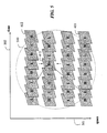
- Figure 5 shows a preferred alternating 'checkerboard pattern' of the low band frames (L) 411 and the high band frames (H) 412 for a neighborhood of frames 510.
- the frames have a spatial (view) dimension 501 and a temporal dimension 502.
- the pattern alternates low band frames and high band frames in the spatial dimension for a single instant in time, and additionally alternates temporally the low band frames and the high band frames for a single video.
- the pattern distributes low band frames evenly in both the space and time dimensions, which achieves scalability in space and time when a decoder only reconstructs the low band frames.
- the pattern aligns the high band frames with adjacent low band frames in both the space and time dimensions. This maximizes the correlation between reference pictures from which the predictions of the errors in the current frame are made, as shown in Figure 6.
- the high band frames 412 are generated by predicting one set of samples from the other set of samples.
- the prediction can be achieved using a number of modes including various forms of temporal prediction, various forms of spatial prediction, and a view synthesis prediction according to the embodiments of invention described below.
- the means by which the high band frames 412 are predicted and the necessary information required to make the prediction are referred to as the side information 413. If a temporal prediction is performed, then the temporal mode is signaled as part of the side information along with corresponding motion information. If a spatial prediction is performed, then the spatial mode is signaled as part of the side information along with corresponding disparity information. If view synthesis prediction is performed, then the view synthesis mode is signaled as part of the side information along with corresponding disparity, motion and depth information.
- each current frame 600 uses neighboring frames 510 in both the space and time dimensions.
- the frames that are used for predicting the current frame are called reference pictures.
- the reference pictures are maintained in the reference list, which is part of the encoded bitstream.
- the reference pictures are stored in the decoded picture buffer.
- the MCTF and DCVF are applied adaptively to each current macroblock for each frame of the input videos to yield decomposed low band frames, as well as the high band frames and the associated side information.
- each macroblock is processed adaptively according to a 'best' prediction mode. An optimal method for selecting the prediction mode is described below.
- the MCTF is first applied to the frames of each video independently.
- the resulting frames are then further decomposed with the DCVF.
- the corresponding side information is also generated. If performed on a macroblock-basis, then the prediction mode selections for the MCTF and the DCVF are considered separately. As an advantage, this prediction mode selection inherently supports temporal scalability. In this way, lower temporal rates of the videos are easily accessed in the compressed bitstream.
- the DCVF is first applied to the frames of the input videos.
- the resulting frames are then temporally decomposed with the MCTF.
- the side information is also generated. If performed on a macroblock-basis, then the prediction mode selections for the MCTF and DCVF are considered separately. As an advantage, this selection inherently supports spatial scalability. In this way, a reduced number of the views are easily accessed in the compressed bitstream.
- the decomposition described above can be applied recursively on the resulting set of low band frames from a previous decomposition stage.
- our MCTF/DCVF decomposition 400 effectively removes both temporal and spatial (inter-view) correlations, and can achieve a very high compression efficiency.
- the compression efficiency of our multiview video encoder outperforms conventional simulcast encoding, which encodes each video for each view independently.
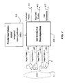
- the outputs 411 and 412 of decomposition 400 are fed to a signal encoder 710, and the output 413 is fed to a side information encoder 720.
- the signal encoder 710 performs a transform, quantization and entropy coding to remove any remaining correlations in the decomposed low band and high band frames 411-412. Such operations are well known in the art, Netravali and Haskell, Digital Pictures: Representation, Compression and Standards, Second Edition, Plenum Press, 1995 .
- the side information encoder 720 encodes the side information 413 generated by the decomposition 400.
- the side information 413 includes motion information corresponding to the temporal predictions, disparity information corresponding to the spatial predictions and view synthesis and depth information corresponding to the view synthesis predictions.
- Encoding the side information can be achieved by known and established techniques, such as the techniques used in the MPEG-4 Visual standard, ISO/IEC 14496-2, " Information technology -- Coding of audio-visual objects - Part 2: Visual,” 2nd Edition, 2001 , or the more recent H.264/AVC standard, and ITU-T Recommendation H.264, "Advanced video coding for generic audiovisual services," 2004 .
- motion vectors of the macroblocks are typically encoded using predictive methods that determine a prediction vector from vectors in macroblocks in reference pictures.
- the difference between the prediction vector and the current vector is then subject to an entropy coding process, which typically uses the statistics of the prediction error.
- An entropy coding process typically uses the statistics of the prediction error.
- a similar procedure can be used to encode disparity vectors.
- depth information for each macroblock can be encoded using predictive coding methods in which a prediction from macroblocks in reference pictures is obtained, or by simply using a fixed length code to express the depth value directly. If pixel level accuracy for the depth is extracted and compressed, then texture coding techniques that apply transform, quantization and entropy coding techniques can be applied.
- the encoded signals 711-713 from the signal encoder 710 and side information encoder 720 can be multiplexed 730 to produce an encoded output bitstream 731.
- the bitstream 731 can be decoded 740 to produce output multiview videos 741 corresponding to the input multiview videos 401-404.
- synthetic video can also be generated.
- the decoder performs the inverse operations of the encoder to reconstruct the multiview videos. If all low band and high band frames are decoded, then the full set of frames in both the space (view) dimension and time dimension at the encoded quality are reconstructed and available.
- view synthesis is a process by which frames 801 of a synthesized video are generated from frames 803 of one or more actual multiview videos.
- view synthesis provides a means to synthesize the frames 801 corresponding to a selected novel view 802 of the scene 5.
- This novel view 802 may correspond to a 'virtual' camera 800 not present at the time the input multiview videos 401-404 were acquired or the view can correspond to a camera view that is acquired, whereby the synthesized view will be used for prediction and encoding/decoding of this view as described below.
- the synthesis is based on extrapolation or warping, and if multiple videos are used, then the synthesis is based on interpolation.
- the pixels in the frames 801 for the synthetic view 802 can be synthesized from the corresponding pixel values in the frames 803.
- View synthesis is commonly used in computer graphics for rendering still images for multiple views, see Buehler et al., "Unstructured Lumigraph Rendering," Proc. ACM SIGGRAPH, 2001. That method requires extrinsic and intrinsic parameters for the cameras.
- Synesized frames to be used for predicting the current frame.
- synthesized frames are generated for designated high band frames.
- synthesized frames are generated for specific views. The synthesized frames serve as reference pictures from which a current synthesized frame can be predicted.
- each synthesized video we generate multiple synthesized frames, each corresponding to a candidate depth value. For each macroblock in the current frame, the best matching macroblock in the set of synthesized frames is determined. The synthesized frame from which this best match is found indicates the depth value of the macroblock in the current frame. This process is repeated for each macroblock in the current frame.
- a difference between the current macroblock and the synthesized block is encoded and compressed by the signal encoder 710.
- the side information for this multiview mode is encoded by the side information encoder 720.
- the side information includes a signal indicating the view synthesis prediction mode, the depth value of the macroblock, and an optional displacement vector that compensates for any misalignments between the macroblock in the current frame and the best matching macroblock in the synthesized frame to be compensated.
- the candidate modes m include various modes of temporal, spatial, view synthesis, and intra prediction.
- the cost function J(m) depends on the rate and distortion resulting from encoding the macroblock using a specific prediction mode m .
- the distortion D measures a difference between a reconstructed macroblock and a source macroblock.
- the reconstructed macroblock is obtained by encoding and decoding the macroblock using the given prediction mode m.
- a common distortion measure is a sum of squared difference.
- the rate R corresponds to the number of bits needed to encode the macroblock, including the prediction error and the side information.
- the weighting parameter ⁇ controls the rate-distortion tradeoff of the macroblock coding, and can be derived from a size of a quantization step.
- FIG. 9 shows a reference picture management for prior art single-view encoding and decoding systems.
- Temporal reference pictures 901 are managed by a single-view reference picture list (RPL) manager 910, which determines insertion 920 and removal 930 of temporal reference pictures 901 to a decoded picture buffer (DPB) 940.
- a reference picture list 950 is also maintained to indicate the frames that are stored in the DPB 940.
- the RPL is used for reference picture management operations such as insert 920 and remove 930, as well as temporal prediction 960 in both the encoded and the decoder.
- the temporal reference pictures 901 are generated as a result of applying a set of typical encoding operations including prediction, transform and quantization, then applying the inverse of those operations including inverse quantization, inverse transform and motion compensation. Furthermore, temporal reference pictures 901 are only inserted into the DPB 940 and added to the RPL 950 when the temporal pictures are required for the prediction of a current frame in the encoder.
- the same temporal reference pictures 901 are generated by applying a set of typical decoding operations on the bitstream including inverse quantization, inverse transform and motion compensation.
- the temporal reference pictures 901 are only inserted 920 into the DPB 940 and added to the RPL 950 if they are required for prediction of a current frame in the decoder.
- Figure 10 shows a reference picture management for multiview encoding and decoding.
- the multiview systems also include spatial reference pictures 1001 and synthesized reference pictures 1002. These reference pictures are collectively referred to as multiview reference pictures 1005.
- the multiview reference pictures 1005 are managed by a multiview RPL manager 1010, which determines insertion 1020 and removal 1030 of the multiview reference pictures 1005 to the multiview DPB 1040.
- a multiview reference picture list (RPL) 1050 is also maintained to indicate the frames that are stored in the DPB. That is, the RPL is an index for the DPB.
- the multiview RPLs are used for reference picture management operations such as insert 1020 and remove 1030, as well as prediction 1060 of the current frame.
- prediction 1060 for the multiview system is different than prediction 960 for the single-view system because prediction from different types of multiview reference pictures 1005 is enabled. Further details on the multiview reference picture management 1010 are described below.
- a set of multiview reference pictures 1005 can be indicated in the multiview RPL 1050.
- a set can have zero (null set), one or multiple elements. Identical copies of the RPLs are maintained by both the encoder and decoder for each current frame.
- All frames inserted in the multiview RPLs 1050 are initialized and marked as usable for prediction using an appropriate syntax.
- the 'used_for_reference' flag is set to '1'.
- reference pictures are initialized so that a frame can be used for prediction in a video encoding system.
- each reference picture is assigned a picture order count (POC).
- POC picture order count
- the POC corresponds to the temporal ordering of a picture, e.g., the frame number.
- All frames used as multiview reference pictures are maintained in the RPL and stored in the DPB in such a way that the frames are treated as conventional reference pictures by the encoder 700 or the decoder 740. This way, the encoding and decoding processes can be conventional. Further details on storing multiview reference pictures are described below. For each current frame to be predicted, the RPL and DPB are updated accordingly.
- the process of maintaining the RPL is coordinated between the encoder 700 and the decoder 740.
- the encoder and decoder maintain identical copies of multiview reference picture list when predicting a particular current frame.
- a number of conventions for maintaining the multiframe reference picture list are possible. Therefore, the particular convention that is used is inserted in the bitstream 731, or provided as sequence level side information, e.g., configuration information that is communicated to the decoder. Furthermore, the convention allows different prediction structures, e.g., 1-D arrays, 2-D arrays, arcs, crosses, and sequences synthesized using view interpolation or warping techniques.
- a synthesized frame is generated by warping a corresponding frame of one of the multiview videos acquired by the cameras.
- a conventional model of the scene can be used during the synthesis.
- the view type indicates whether the reference picture is a frame from a video other than the video of the current frame, or whether the reference picture is synthesized from other frames, or whether the reference picture depends on other reference pictures.
- synthesized reference pictures can be maintained differently than reference pictures from the same video as the current frame, or reference pictures from spatially adjacent videos.
- the insertion order indicates how reference pictures are ordered in the RPL. For instance, a reference picture in the same video as the current frame can be given a lower order value than a reference picture in a video taken from an adjacent view. In this case, the reference picture is placed earlier in the multiview RPL.
- Camera properties indicate properties of the camera that is used to acquire the reference picture, or the virtual camera that is used to generate a synthetic reference picture. These properties include translation and rotation relative to a fixed coordinate system, i.e., the camera 'pose', intrinsic parameters describing how a 3-D point is projected into a 2-D image, lens distortions, color calibration information, illumination levels, etc. For instance, based on the camera properties, the proximity of certain cameras to adjacent cameras can be determined automatically, and only videos acquired by adjacent cameras are considered as part of a particular RPL.
- one embodiment of our invention uses a convention that reserves a portion 1101 of each reference picture list for temporal reference pictures 1003, reserves another portion 1102 for synthesized reference pictures 1002 and a third portion 1103 for spatial reference pictures 1001. This is an example of a convention that is dependent only on the view type.
- the number of frames contained in each portion can vary based on a prediction dependency of the current frame being encoded or decoded.
- the particular maintenance convention can be specified by standard, explicit or implicit rules, or in the encoded bitstream as side information.
- the multiview RPL manager 1010 maintains the RPL so that the order in which the multiview reference pictures are stored in the DPB corresponds to their 'usefulness' to improve the efficiency of the encoding and decoding. Specifically, reference pictures in the beginning of the RPL can be predicatively encoded with fewer bits than reference pictures at the end of the RPL.
- multiview reference pictures can be assigned a very large POC value because they do not occur in the normal temporal ordering of a video sequence. Therefore, the default ordering process of most video codecs can place such multiview reference pictures earlier in the reference picture lists.
- the multiview reference pictures are either explicitly reordered by the encoder, whereby the encoder then signals this reordering to the decoder, or the encoder and decoder implicitly reorder multiview reference pictures according to a predetermined convention.
- the order of the reference pictures is facilitated by a view mode 1300 to each reference picture. It is noted that the view mode 1300 also affects the multiview prediction process 1060. In one embodiment of our invention, we use three different types of view modes, I-view, P-view and B-view, which are described in further detail below.
- FIG. 14 Before describing the detailed operation of multiview reference picture management, prior art reference picture management for single video encoding and decoding systems is shown in Figure 14. Only temporal reference pictures 901 are used for the temporal prediction 960. The temporal prediction dependency between temporal reference pictures of the video in acquisition or display order 1401 is shown. The reference pictures are reordered 1410 into an encoding order 1402, in which each reference picture is encoded or decoded at a time instants t 0 - t 6 .
- Block 1420 shows the ordering of the reference pictures for each instant in time. At time t 0 , when an intra-frame I 0 is encoded or decoded, there are no temporal reference pictures used for temporal prediction, hence the DBP/RPL is empty.
- frame I 0 is available as a temporal reference picture.
- both frames I 0 and P 1 are available as reference frames for bi-directional temporal prediction of inter-frames B 1 and B 2 .
- the temporal reference pictures and DBP/RPL are managed in a similar way for future pictures.
- FIG. 15 To describe the multiview case according to an embodiment of the invention, we consider the three different types of views described above and shown in Figure 15: 1-view, P-view, and B-view.
- the multiview prediction dependency between reference pictures of the videos in display order 1501 is shown.
- the reference pictures of the videos are reordered 1510 into a coding order 1502 for each view mode, in which each reference picture is encoded or decoded at a given time instant denoted to - t 2 .
- the order of the multiview reference pictures is shown in block 1520 for each time instant.
- the I-view is the simplest mode that enables more complex modes. I-view uses conventional encoding and prediction modes, without any spatial or synthesized prediction. For example, I-views can be encoded using conventional H.264/AVC techniques without any multiview extensions. When spatial reference pictures from an I-view sequence are placed into the reference lists of other views, these spatial reference pictures are usually placed after temporal reference pictures.
- P-view is more complex than I-view in that P-view allows prediction from another view to exploit the spatial correlation between views.
- sequences encoded using the P-view mode use multiview reference pictures from other I-view or P-view. Synthesized reference pictures can also be used in the P-view.
- P-views are placed after both temporal reference pictures and after multiview references pictures derived from I-views.
- a synthesized reference picture S 20 and the spatial reference picture I 0 are available for prediction. Further details on the generation of synthesized pictures are described below.
- I 2 is available as a temporal reference picture, along with a synthesized reference picture S 21 and a spatial reference picture P 0 from the I-view.
- there exist two temporal reference pictures I 2 and P 2 as well as a synthesized reference picture S 22 and a spatial reference picture B 0 , from which predictions can be made.
- B-views are similar to P-views in that the B-views use multiview reference pictures.
- One key difference between P-views and B-views is that P-views use reference pictures from its own view as well as one other view, while B-views may reference pictures in multiple views.
- synthesized reference pictures are used, the B-views are placed before spatial reference pictures because synthesized views generally have a stronger correlation than spatial references.
- the example shown in Figure 15 is only for one embodiment of the invention. Many different types of prediction dependencies are supported.
- the spatial reference pictures are not limited to pictures in different views at the same time instant. Spatial reference pictures can also include reference pictures for different views at different time instants.
- the number of bi-directionally predicted pictures between intra-pictures and unidirectionally predicted inter-pictures can vary.
- the configuration of I-views, P-views, and B-views can also vary.
- multiview picture management is that it is compatible with existing single-view video coding systems and designs. Not only does this provide minimal changes to the existing single-view video coding standards, but it also enables software and hardware from existing single view video coding systems to be used for multiview video coding as described herein.
- the syntax for communicating such parameters is specified by the existing video coding standards, such as the H.264/AVC standard.
- the video coding standard specifies a prediction mode for a given macroblock in a current frame from other temporally related reference pictures.
- the standard also specifies methods used to encode and decode a resulting prediction error.
- Other parameters specify a type or size of a transform, a quantization method, and an entropy coding method.
- our multiview reference pictures can be implemented with only limited number of modifications to standard encoding and decoding components such as the reference picture lists, decoded picture buffer, and prediction structure of existing systems. It is noted that the macroblock structure, transforms, quantization and entropy encoding remain unchanged.
- view synthesis is a process by which frames 801 corresponding to a synthetic view 802 of a virtual camera 800 are generated from frames 803 acquired of existing videos.
- view synthesis provides a means to synthesize the frames corresponding to a selected novel view of the scene by a virtual camera not present at the time the input videos were acquired.
- the pixels in the frames of the synthesized video view can be generated by extrapolation and/or interpolation.
- Figure 16 shows a process for generating a reconstructed macroblock using the view-synthesis mode, when depth 1901 information is included in the encoded multiview bitstream 731.
- the depth for a given macroblock is decoded by a side information decoder 1910.
- the depth 1901 and the spatial reference pictures 1902 are used to perform view synthesis 1920, where a synthesized macroblock 1904 is generated.
- a reconstructed macroblock 1903 is then formed by adding 1930 the synthesized macroblock 1904 and a decoded residual macroblock 1905.
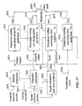
- Figure 17 shows a process for selecting the prediction mode while encoding or decoding a current frame.
- Motion estimation 2010 for a current macroblock 2011 is performed using temporal reference pictures 2020.
- the resultant motion vectors 2021 are used to determine 2030 a first coding cost, cost 1 2031, using temporal prediction.
- the prediction mode associated with this process is m 1 .
- Disparity estimation 2040 for the current macroblock is performed using spatial reference pictures 2041.
- the resultant disparity vectors 2042 are used to determine 2050 a second coding cost, cost 2 2051, using spatial prediction.
- the prediction mode associated with this process is denoted m 2 .
- Depth estimation 2060 for the current macroblock is performed based on the spatial reference pictures 2041. View synthesis is performed based on the estimated depth. The depth information 2061 and the synthesized view 2062 are used to determine 2070 a third coding cost, cost 3 2071, using view-synthesis prediction. The prediction mode associated this process is m 3 .
- Adjacent pixels 2082 of the current macroblock are used to determine 2080 a fourth coding cost, cost 4 2081, using intra prediction.
- the prediction mode associated with process is m 4 .
- the minimum cost among cost 1 , cost 2 , cost 3 and cost 4 is determined 2090, and one of the modes m 1 , m 2 , m 3 and m 4 that has the minimum cost is selected as the best prediction mode 2091 for the current macroblock 2011.
- the depth information and displacement vectors for synthesized views can be estimated from decoded frames of one or more multiview videos.
- the depth information can be per-pixel depth estimated from stereo cameras, or it can be per-macroblock depth estimated from macroblock matching, depending on the process applied.
- An advantage of this approach is a reduced bandwidth because depth values and displacement vectors are not needed in the bitstream, as long as the encoder has access to the same depth and displacement information as the decoder.
- the encoder can achieve this as long as the decoder uses exactly the same depth and displacement estimation process as the encoder. Therefore, in this embodiment of the invention, a difference between the current macroblock and the synthesized macroblock is encoded by the encoder.
- the side information for this mode is encoded by the side information encoder 720.
- the side information includes a signal indicating the view synthesis mode and the reference view(s).
- the side information can also include depth and displacement correction information, which is the difference between the depth and displacement used by the encoder for view synthesis and the values estimated by the decoder.
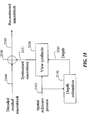
- Figure 18 shows the decoding process for a macroblock using the view-synthesis mode when the depth information is estimated or inferred in the decoder and is not conveyed in the encoded multiview bitstream.
- the depth 2101 is estimated 2110 from the spatial reference pictures 2102.
- the estimated depth and the spatial reference pictures are then used to perform view synthesis 2120, where a synthesized macroblock 2121 is generated.
- a reconstructed macroblock 2103 is formed by the addition 2130 of the synthesized macroblock and the decoded residual macroblock 2104.
- intra-frames also known as I-frames
- I-frames intra-frames
- V-frames are frames in the compressed bitstream that are predicted from spatial reference pictures or synthesized reference pictures.
- Figure 19 shows the use of I-frames for the initial view and the use of V-frames for subsequent views at the same time instant 1900. It is noted that for the checkerboard configuration shown in Figure 5, V-frames would not occur at the same time instant for all views. Any of the low-band frames could be assigned a V-frame. In this case, the V-frames would be predicted from low-band frames of neighboring views.
- IDR frames which are similar to MPEG-2 I-frames with closed GOP, imply that all reference pictures are removed from the decoder picture buffer. In this way, the frame before an IDR frame cannot be used to predict frames after the IDR frame.
- V-frames similarly imply that all temporal reference pictures can be removed from the decoder picture buffer.
- spatial reference pictures can remain in the decoder picture buffer. In this way, a frame in a given view before the V-frame cannot be used to perform temporal prediction for a frame in the same view after the V-frame.
- the V-frame for that view must first be decoded. As described above, this can be achieved through prediction from spatial reference pictures or synthesized reference pictures, without the use of temporal reference pictures.
Landscapes
- Engineering & Computer Science (AREA)
- Multimedia (AREA)
- Signal Processing (AREA)
- Compression Or Coding Systems Of Tv Signals (AREA)
Abstract
Description
- This invention relates generally to encoding and decoding multiview videos, and more particularly to managing reference pictures while encoding and decoding multiview videos.
- Multiview video encoding and decoding is essential for applications such as three dimensional television (3DTV), free viewpoint television (FTV), and multicamera surveillance. Multiview video encoding and decoding is also known as dynamic light field compression.
- Figure 1 shows a prior art 'simulcast'
system 100 for multiview video encoding. Cameras 1-4 acquire sequences of frames or videos 101-104 of ascene 5. Each camera has a different view of the scene. Each video is encoded 111-114 independently to corresponding encoded videos 121-124. That system uses conventional 2D video encoding techniques. Therefore, that system does not correlate between the different videos acquired by the cameras from the different viewpoints while predicting frames of the encoded video. Independent encoding decreases compression efficiency, and thus network bandwidth and storage are increased. - Figure 2 shows a prior art disparity compensated
prediction system 200 that does use inter-view correlations. Videos 201-204 are encoded 211-214 to encoded videos 231-234. Thevideos remaining videos reference videos decoders - Figure 3 shows prior art 'lifting-based' wavelet decomposition, see W. Sweldens, "The data compression of simplified dynamic light fields," J. Appl. Comp. Harm. Anal., vol. 3, no. 2, pp. 186-200, 1996. Wavelet decomposition is an effective technique for static light field compression.
Input samples 301 are split 310 intoodd samples 302 and evensamples 303. The odd samples are predicted 320 from the even samples. A prediction error formshigh band samples 304. The high band samples are used to update 330 the even samples and to formlow band samples 305. That decomposition is invertible so that linear or non-linear operations can be incorporated into the prediction and update steps. - The lifting scheme enables a motion-compensated temporal transform, i.e., motion compensated temporal filtering (MCTF) which, for videos, essentially filters along a temporal motion trajectory. A review of MCTF for video coding is described by Ohm et al., "Interframe wavelet coding - motion picture representation for universal scalability," Signal Processing: Image Communication, vol. 19, no. 9, pp. 877-908, October 2004. The lifting scheme can be based on any wavelet kernel such as Harr or 5/3 Daubechies, and any motion model such as block-based translation or affine global motion, without affecting the reconstruction.
- For encoding, the MCTF decomposes the video into high band frames and low band frames. Then, the frames are subjected to spatial transforms to reduce any remaining spatial correlations. The transformed low and high band frames, along with associated motion information, are entropy encoded to form an encoded bitstream. MCTF can be implemented using the lifting scheme shown in Figure 3 with the temporally adjacent videos as input. In addition, MCTF can be applied recursively to the output low band frames.
- MCTF-based videos have a compression efficiency comparable to that of video compression standards such as H.264/AVC. In addition, the videos have inherent temporal scalability. However, that method cannot be used for directly encoding multiview videos in which there is a correlation between videos acquired from multiple views because there is no efficient method for predicting views that accounts for correlation in time.
- The lifting scheme has also been used to encode static light fields, i.e., single multiview images. Rather than performing a motion-compensated temporal filtering, the encoder performs a disparity compensated inter-view filtering (DCVF) across the static views in the spatial domain, see Chang et al., "Inter-view wavelet compression of light fields with disparity compensated lifting," SPIE Conf on Visual Communications and Image Processing, 2003. For encoding, DCVF decomposes the static light field into high and low band images, which are then subject to spatial transforms to reduce any remaining spatial correlations. The transformed images, along with the associated disparity information, are entropy encoded to form the encoded bitstream. DCVF is typically implemented using the lifting-based wavelet transform scheme as shown in Figure 3 with the images acquired from spatially adjacent camera views as input. In addition, DCVF can be applied recursively to the output low band images. DCVF-based static light field compression provides a better compression efficiency than independently coding the multiple frames. However, that method also cannot encode multiview videos in which both temporal correlation and spatial correlation between views are used because there is no efficient method for predicting views that account for correlation in time.
- A method and system to decompose multiview videos acquired of a scene by multiple cameras is presented.
- Each multiview video includes a sequence of frames, and each camera provides a different view of the scene.
- A prediction mode is selected from a temporal, spatial, view synthesis, and intra-prediction mode.
- The multiview videos are then decomposed into low band frames, high band frames, and side information according to the selected prediction mode.
- A novel video reflecting a synthetic view of the scene can also be generated from one or more of the multiview videos.
- More particularly, one embodiment of the invention provides a system and method for managing multiview videos. A reference picture list is maintained for each current frame of multiple multiview videos. The reference picture list indexes temporal reference pictures, spatial reference pictures and synthesized reference pictures of the multiview videos. Then, each current frame of the multiview videos is predicted according to reference pictures indexed by the associated reference picture list during encoding and decoding.
- Figure 1 is a block diagram of a prior art system for encoding multiview videos;
- Figure 2 is a block diagram of a prior art disparity compensated prediction system for encoding multiview videos;
- Figure 3 is a flow diagram of a prior art wavelet decomposition process;
- Figure 4 is a block diagram of a MCTF/DCVF decomposition according to an embodiment of the invention;
- Figure 5 is a block diagram of low-band frames and high band frames as a function of time and space after the MCTF/DCVF decomposition according to an embodiment of the invention;
- Figure 6 is a block diagram of prediction of high band frame from adjacent low-band frames according to an embodiment of the invention;
- Figure 7 is a block diagram of a multiview coding system using macroblock-adaptive MCTF/DCVF decomposition according to an embodiment of the invention;
- Figure 8 is a schematic of video synthesis according to an embodiment of the invention;
- Figure 9 is a block diagram of a prior art reference picture management;
- Figure 10 is a block diagram of multiview reference picture management according to an embodiment of the invention;
- Figure 11 is a block diagram of multiview reference pictures in a decoded picture buffer according to an embodiment of the invention;
- Figure 12 is a graph comparing coding efficiencies of different multiview reference picture orderings;
- Figure 13 is a block diagram of dependencies of view mode on the multiview reference picture list manager according to an embodiment of the invention;
- Figure 14 is diagram of a prior art reference picture management for single view coding systems that employ prediction from temporal reference pictures;
- Figure 15 is a diagram of a reference picture management for multiview coding and decoding systems that employ prediction from multiview reference pictures according to an embodiment of the invention;
- Figure 16 is a block diagram of view synthesis in a decoder using depth information encoded and received as side information according to an embodiment of the invention;
- Figure 17 is a block diagram of cost calculations for selecting a prediction mode according to an embodiment of the invention;
- Figure 18 is a block diagram of view synthesis in a decoder using depth information estimated by a decoder according to an embodiment of the invention; and
- Figure 19 is a block diagram of multiview videos using V-frames to achieve spatial random access in the decoder according to an embodiment of the invention.
- One embodiment of our invention provides a joint temporal/inter-view processing method for encoding and decoding frames of multiview videos. Multiview videos are videos that are acquired of a scene by multiple cameras having different poses. We define a pose camera as both its 3D (x, y, z) position, and its 3D (θ, p, ϕ) orientation. Each pose corresponds to a 'view' of the scene.
- The method uses temporal correlation between frames within each video acquired for a particular camera pose, as well as spatial correlation between synchronized frames in videos acquired from multiple camera views. In addition, 'synthetic' frames can be correlated, as described below.
- In one embodiment, the temporal correlation uses motion compensated temporal filtering (MCTF), while the spatial correlation uses disparity compensated inter-view filtering (DCVF).
- In another embodiment of the invention, spatial correlation uses prediction of one view from synthesized frames that are generated from 'neighboring' frames. Neighboring frames are temporally or spatially adjacent frames, for example, frames before or after a current frame in the temporal domain, or one or more frames acquired at the same instant in time but from cameras having different poses or views of the scene.
- Each frame of each video includes macroblocks of pixels. Therefore, the method of multiview video encoding and decoding according to one embodiment of the invention is macroblock adaptive. The encoding and decoding of a current macroblock in a current frame is performed using several possible prediction modes, including various forms of temporal, spatial, view synthesis, and intra prediction. To determine the best prediction mode on a macroblock basis, one embodiment of the invention provides a method for selecting a prediction mode. The method can be used for any number of camera arrangements.
- In order to maintain compatibility with existing single-view encoding and decoding systems, a method for managing a reference picture list is described. Specifically, we describe a method of inserting and removing reference pictures from a picture buffer according to the reference picture list. The reference pictures include temporal reference pictures, spatial reference pictures and synthesized reference pictures.
- As used herein, a reference picture is defmed as any frame that is used during the encoding and decoding to 'predict' a current frame. Typically, reference pictures are spatially or temporally adjacent or 'neighboring' to the current frame.
- It is important to note that the same operations are applied in both the encoder and decoder because the same set of reference pictures are used at any give time instant to encode and decode the current frame.
- One embodiment of the invention enables random access to the frames of the multiview videos during encoding and decoding. This improves coding efficiency.
- MCTF/DCVF Decomposition
- Figure 4 show a MCTF/
DCVF decomposition 400 according to one embodiment of the invention. Frames of input videos 401-404 are acquired of ascene 5 by cameras 1-4 having different posses. Note, as shown in Fig 8, some of thecameras 1a and 1b can be at the same locations but with different orientations. It is assumed that there is some amount of view overlap between any pair of cameras. The poses of the cameras can change while acquiring the multiview videos. Typically, the cameras are synchronized with each other. Each input video provides a different 'view' of the scene. The input frames 401-404 are sent to a MCTF/DCVF decomposition 400. The decomposition produces encoded low-band frames 411, encoded high band frames 412, and associatedside information 413. The high band frames encode prediction errors using the low band frames as reference pictures. The decomposition is according to selectedprediction modes 410. The prediction modes include spatial, temporal, view synthesis, and intra prediction modes. The prediction modes can be selected adaptively on a per macroblock basis for each current frame. With intra prediction, the current macroblock is predicted from other macroblocks in the same frame. - Figure 5 shows a preferred alternating 'checkerboard pattern' of the low band frames (L) 411 and the high band frames (H) 412 for a neighborhood of
frames 510. The frames have a spatial (view)dimension 501 and atemporal dimension 502. Essentially, the pattern alternates low band frames and high band frames in the spatial dimension for a single instant in time, and additionally alternates temporally the low band frames and the high band frames for a single video. - There are several advantages of this checkerboard pattern. The pattern distributes low band frames evenly in both the space and time dimensions, which achieves scalability in space and time when a decoder only reconstructs the low band frames. In addition, the pattern aligns the high band frames with adjacent low band frames in both the space and time dimensions. This maximizes the correlation between reference pictures from which the predictions of the errors in the current frame are made, as shown in Figure 6.
- According to a lifting-based wavelet transform, the high band frames 412 are generated by predicting one set of samples from the other set of samples. The prediction can be achieved using a number of modes including various forms of temporal prediction, various forms of spatial prediction, and a view synthesis prediction according to the embodiments of invention described below.
- The means by which the high band frames 412 are predicted and the necessary information required to make the prediction are referred to as the
side information 413. If a temporal prediction is performed, then the temporal mode is signaled as part of the side information along with corresponding motion information. If a spatial prediction is performed, then the spatial mode is signaled as part of the side information along with corresponding disparity information. If view synthesis prediction is performed, then the view synthesis mode is signaled as part of the side information along with corresponding disparity, motion and depth information. - As shown in Figures 6, the prediction of each
current frame 600uses neighboring frames 510 in both the space and time dimensions. The frames that are used for predicting the current frame are called reference pictures. The reference pictures are maintained in the reference list, which is part of the encoded bitstream. The reference pictures are stored in the decoded picture buffer. - In one embodiment of the invention, the MCTF and DCVF are applied adaptively to each current macroblock for each frame of the input videos to yield decomposed low band frames, as well as the high band frames and the associated side information. In this way, each macroblock is processed adaptively according to a 'best' prediction mode. An optimal method for selecting the prediction mode is described below.
- In one embodiment of the invention, the MCTF is first applied to the frames of each video independently. The resulting frames are then further decomposed with the DCVF. In addition to the final decomposed frames, the corresponding side information is also generated. If performed on a macroblock-basis, then the prediction mode selections for the MCTF and the DCVF are considered separately. As an advantage, this prediction mode selection inherently supports temporal scalability. In this way, lower temporal rates of the videos are easily accessed in the compressed bitstream.
- In another embodiment, the DCVF is first applied to the frames of the input videos. The resulting frames are then temporally decomposed with the MCTF. In addition to the final decomposed frames, the side information is also generated. If performed on a macroblock-basis, then the prediction mode selections for the MCTF and DCVF are considered separately. As an advantage, this selection inherently supports spatial scalability. In this way, a reduced number of the views are easily accessed in the compressed bitstream.
- The decomposition described above can be applied recursively on the resulting set of low band frames from a previous decomposition stage. As an advantage, our MCTF/
DCVF decomposition 400 effectively removes both temporal and spatial (inter-view) correlations, and can achieve a very high compression efficiency. The compression efficiency of our multiview video encoder outperforms conventional simulcast encoding, which encodes each video for each view independently. - Coding of MCTF/DCVF Decomposition
- As shown in Figure 7, the
outputs decomposition 400 are fed to asignal encoder 710, and theoutput 413 is fed to aside information encoder 720. Thesignal encoder 710 performs a transform, quantization and entropy coding to remove any remaining correlations in the decomposed low band and high band frames 411-412. Such operations are well known in the art, Netravali and Haskell, Digital Pictures: Representation, Compression and Standards, Second Edition, Plenum Press, 1995. - The
side information encoder 720 encodes theside information 413 generated by thedecomposition 400. In addition to the prediction mode and the reference picture list, theside information 413 includes motion information corresponding to the temporal predictions, disparity information corresponding to the spatial predictions and view synthesis and depth information corresponding to the view synthesis predictions. - Encoding the side information can be achieved by known and established techniques, such as the techniques used in the MPEG-4 Visual standard, ISO/IEC 14496-2, "Information technology -- Coding of audio-visual objects - Part 2: Visual," 2nd Edition, 2001, or the more recent H.264/AVC standard, and ITU-T Recommendation H.264, "Advanced video coding for generic audiovisual services," 2004.
- For instance, motion vectors of the macroblocks are typically encoded using predictive methods that determine a prediction vector from vectors in macroblocks in reference pictures. The difference between the prediction vector and the current vector is then subject to an entropy coding process, which typically uses the statistics of the prediction error. A similar procedure can be used to encode disparity vectors.
- Furthermore, depth information for each macroblock can be encoded using predictive coding methods in which a prediction from macroblocks in reference pictures is obtained, or by simply using a fixed length code to express the depth value directly. If pixel level accuracy for the depth is extracted and compressed, then texture coding techniques that apply transform, quantization and entropy coding techniques can be applied.
- The encoded signals 711-713 from the
signal encoder 710 andside information encoder 720 can be multiplexed 730 to produce an encodedoutput bitstream 731. - Decoding of MCTF/DCVF Decomposition
- The
bitstream 731 can be decoded 740 to produce outputmultiview videos 741 corresponding to the input multiview videos 401-404. Optionally, synthetic video can also be generated. Generally, the decoder performs the inverse operations of the encoder to reconstruct the multiview videos. If all low band and high band frames are decoded, then the full set of frames in both the space (view) dimension and time dimension at the encoded quality are reconstructed and available. - Depending on the number of recursive levels of decomposition that were applied in the encoder and which type of decompositions were applied, a reduced number of videos and/or a reduced temporal rate can be decoded as shown in Figure 7.
- View Synthesis
- As shown in Figure 8, view synthesis is a process by which frames 801 of a synthesized video are generated from
frames 803 of one or more actual multiview videos. In other words, view synthesis provides a means to synthesize theframes 801 corresponding to a selectednovel view 802 of thescene 5. Thisnovel view 802 may correspond to a 'virtual'camera 800 not present at the time the input multiview videos 401-404 were acquired or the view can correspond to a camera view that is acquired, whereby the synthesized view will be used for prediction and encoding/decoding of this view as described below. - If one video is used, then the synthesis is based on extrapolation or warping, and if multiple videos are used, then the synthesis is based on interpolation.
- Given the pixel values of
frames 803 of one or more multiview videos and the depth values of points in the scene, the pixels in theframes 801 for thesynthetic view 802 can be synthesized from the corresponding pixel values in theframes 803. - View synthesis is commonly used in computer graphics for rendering still images for multiple views, see Buehler et al., "Unstructured Lumigraph Rendering," Proc. ACM SIGGRAPH, 2001. That method requires extrinsic and intrinsic parameters for the cameras.
- View synthesis for compressing multiview videos is novel. In one embodiment of our invention, we generate synthesized frames to be used for predicting the current frame. In one embodiment of the invention, synthesized frames are generated for designated high band frames. In another embodiment of the invention, synthesized frames are generated for specific views. The synthesized frames serve as reference pictures from which a current synthesized frame can be predicted.
- One difficulty with this approach is that the depth values of the
scene 5 are unknown. Therefore, we estimate the depth values using known techniques, e.g., based on correspondences of features in the multiview videos. - Alternatively, for each synthesized video, we generate multiple synthesized frames, each corresponding to a candidate depth value. For each macroblock in the current frame, the best matching macroblock in the set of synthesized frames is determined. The synthesized frame from which this best match is found indicates the depth value of the macroblock in the current frame. This process is repeated for each macroblock in the current frame.
- A difference between the current macroblock and the synthesized block is encoded and compressed by the
signal encoder 710. The side information for this multiview mode is encoded by theside information encoder 720. The side information includes a signal indicating the view synthesis prediction mode, the depth value of the macroblock, and an optional displacement vector that compensates for any misalignments between the macroblock in the current frame and the best matching macroblock in the synthesized frame to be compensated. - Prediction Mode Selection
- In the macroblock-adaptive MCTF/DCVF decomposition, the prediction mode m for each macroblock can be selected by minimizing a cost function adaptively on a per macroblock basis:

where J(m) = D(m) + λR(m), and D is distortion, λ is a weighting parameter, R is rate, m indicates the set of candidate prediction modes, and m* indicates the optimal prediction mode that has been selected based on a minimum cost criteria. - The candidate modes m include various modes of temporal, spatial, view synthesis, and intra prediction. The cost function J(m) depends on the rate and distortion resulting from encoding the macroblock using a specific prediction mode m.
- The distortion D measures a difference between a reconstructed macroblock and a source macroblock. The reconstructed macroblock is obtained by encoding and decoding the macroblock using the given prediction mode m. A common distortion measure is a sum of squared difference. The rate R corresponds to the number of bits needed to encode the macroblock, including the prediction error and the side information. The weighting parameter λ controls the rate-distortion tradeoff of the macroblock coding, and can be derived from a size of a quantization step.
- Detailed aspects of the encoding and decoding processes are described in further detail below. In particular, the various data structures that are used by the encoding and decoding processes are described. It should be understood that the data structures, as described herein, that are used in the encoder are identical to corresponding data structures used in the decoder. It should also be understood that the processing steps of the decoder essentially follow the same processing steps as the encoder, but in an inverse order.
- Reference Picture Management
- Figure 9 shows a reference picture management for prior art single-view encoding and decoding systems.
Temporal reference pictures 901 are managed by a single-view reference picture list (RPL)manager 910, which determinesinsertion 920 andremoval 930 oftemporal reference pictures 901 to a decoded picture buffer (DPB) 940. Areference picture list 950 is also maintained to indicate the frames that are stored in theDPB 940. The RPL is used for reference picture management operations such asinsert 920 and remove 930, as well astemporal prediction 960 in both the encoded and the decoder. - In single-view encoders, the
temporal reference pictures 901 are generated as a result of applying a set of typical encoding operations including prediction, transform and quantization, then applying the inverse of those operations including inverse quantization, inverse transform and motion compensation. Furthermore,temporal reference pictures 901 are only inserted into theDPB 940 and added to theRPL 950 when the temporal pictures are required for the prediction of a current frame in the encoder. - In single-view decoders, the same
temporal reference pictures 901 are generated by applying a set of typical decoding operations on the bitstream including inverse quantization, inverse transform and motion compensation. As in the encoder, thetemporal reference pictures 901 are only inserted 920 into theDPB 940 and added to theRPL 950 if they are required for prediction of a current frame in the decoder. - Figure 10 shows a reference picture management for multiview encoding and decoding. In addition to
temporal reference pictures 1003, the multiview systems also includespatial reference pictures 1001 and synthesized reference pictures 1002. These reference pictures are collectively referred to as multiview reference pictures 1005. Themultiview reference pictures 1005 are managed by amultiview RPL manager 1010, which determinesinsertion 1020 andremoval 1030 of themultiview reference pictures 1005 to themultiview DPB 1040. For each video, a multiview reference picture list (RPL) 1050 is also maintained to indicate the frames that are stored in the DPB. That is, the RPL is an index for the DPB. The multiview RPLs are used for reference picture management operations such asinsert 1020 and remove 1030, as well asprediction 1060 of the current frame. - It is noted that
prediction 1060 for the multiview system is different thanprediction 960 for the single-view system because prediction from different types ofmultiview reference pictures 1005 is enabled. Further details on the multiviewreference picture management 1010 are described below. - Multiview Reference Picture List Manager
- Before encoding a current frame in the encoder or before decoding the current frame in the decoder, a set of
multiview reference pictures 1005 can be indicated in themultiview RPL 1050. As defined conventionally and herein, a set can have zero (null set), one or multiple elements. Identical copies of the RPLs are maintained by both the encoder and decoder for each current frame. - All frames inserted in the
multiview RPLs 1050 are initialized and marked as usable for prediction using an appropriate syntax. According to the H.264/AVC standard and reference software, the 'used_for_reference' flag is set to '1'. In general, reference pictures are initialized so that a frame can be used for prediction in a video encoding system. To maintain compatibility with conventional single-view video compression standards, such as H.264/AVC, each reference picture is assigned a picture order count (POC). Typically, for single-view encoding and decoding systems, the POC corresponds to the temporal ordering of a picture, e.g., the frame number. For multiview encoding and decoding systems, temporal order alone is not sufficient to assign a POC for each reference picture. Therefore, we determine a unique POC for every multiview reference picture according to a convention. One convention is to assign a POC for temporal reference pictures based on temporal order, and then to reserve a sequence of very high POC numbers, e.g., 10,000 - 10,100, for the spatial and synthesized reference pictures. Other POC assignment conventions, or simply "ordering" conventions, are described in further detail below. - All frames used as multiview reference pictures are maintained in the RPL and stored in the DPB in such a way that the frames are treated as conventional reference pictures by the
encoder 700 or thedecoder 740. This way, the encoding and decoding processes can be conventional. Further details on storing multiview reference pictures are described below. For each current frame to be predicted, the RPL and DPB are updated accordingly. - Defining and Signaling Multiview Conventions
- The process of maintaining the RPL is coordinated between the
encoder 700 and thedecoder 740. In particular, the encoder and decoder maintain identical copies of multiview reference picture list when predicting a particular current frame. - A number of conventions for maintaining the multiframe reference picture list are possible. Therefore, the particular convention that is used is inserted in the
bitstream 731, or provided as sequence level side information, e.g., configuration information that is communicated to the decoder. Furthermore, the convention allows different prediction structures, e.g., 1-D arrays, 2-D arrays, arcs, crosses, and sequences synthesized using view interpolation or warping techniques. - For example, a synthesized frame is generated by warping a corresponding frame of one of the multiview videos acquired by the cameras. Alternatively, a conventional model of the scene can be used during the synthesis. In other embodiments of our invention, we define several multiview reference picture maintenance conventions that are dependent on view type, insertion order, and camera properties.
- The view type indicates whether the reference picture is a frame from a video other than the video of the current frame, or whether the reference picture is synthesized from other frames, or whether the reference picture depends on other reference pictures. For example, synthesized reference pictures can be maintained differently than reference pictures from the same video as the current frame, or reference pictures from spatially adjacent videos.
- The insertion order indicates how reference pictures are ordered in the RPL. For instance, a reference picture in the same video as the current frame can be given a lower order value than a reference picture in a video taken from an adjacent view. In this case, the reference picture is placed earlier in the multiview RPL.
- Camera properties indicate properties of the camera that is used to acquire the reference picture, or the virtual camera that is used to generate a synthetic reference picture. These properties include translation and rotation relative to a fixed coordinate system, i.e., the camera 'pose', intrinsic parameters describing how a 3-D point is projected into a 2-D image, lens distortions, color calibration information, illumination levels, etc. For instance, based on the camera properties, the proximity of certain cameras to adjacent cameras can be determined automatically, and only videos acquired by adjacent cameras are considered as part of a particular RPL.
- As shown in Figure 11, one embodiment of our invention uses a convention that reserves a
portion 1101 of each reference picture list fortemporal reference pictures 1003, reserves anotherportion 1102 for synthesizedreference pictures 1002 and athird portion 1103 for spatial reference pictures 1001. This is an example of a convention that is dependent only on the view type. The number of frames contained in each portion can vary based on a prediction dependency of the current frame being encoded or decoded. - The particular maintenance convention can be specified by standard, explicit or implicit rules, or in the encoded bitstream as side information.
- Storing Pictures in the DPB
- The
multiview RPL manager 1010 maintains the RPL so that the order in which the multiview reference pictures are stored in the DPB corresponds to their 'usefulness' to improve the efficiency of the encoding and decoding. Specifically, reference pictures in the beginning of the RPL can be predicatively encoded with fewer bits than reference pictures at the end of the RPL. - As shown in Figure 12, optimizing the order in which multiview references pictures are maintained in the RPL can have a significant impact on coding efficiency. For example, following the POC assignment described above for initialization, multiview reference pictures can be assigned a very large POC value because they do not occur in the normal temporal ordering of a video sequence. Therefore, the default ordering process of most video codecs can place such multiview reference pictures earlier in the reference picture lists.
- Because temporal reference pictures from the same sequence generally exhibit stronger correlations than spatial reference pictures from other sequences, the default ordering is undesirable. Therefore, the multiview reference pictures are either explicitly reordered by the encoder, whereby the encoder then signals this reordering to the decoder, or the encoder and decoder implicitly reorder multiview reference pictures according to a predetermined convention.
- As shown in Figure 13, the order of the reference pictures is facilitated by a
view mode 1300 to each reference picture. It is noted that theview mode 1300 also affects themultiview prediction process 1060. In one embodiment of our invention, we use three different types of view modes, I-view, P-view and B-view, which are described in further detail below. - Before describing the detailed operation of multiview reference picture management, prior art reference picture management for single video encoding and decoding systems is shown in Figure 14. Only
temporal reference pictures 901 are used for thetemporal prediction 960. The temporal prediction dependency between temporal reference pictures of the video in acquisition ordisplay order 1401 is shown. The reference pictures are reordered 1410 into anencoding order 1402, in which each reference picture is encoded or decoded at a time instants t0 - t6.Block 1420 shows the ordering of the reference pictures for each instant in time. At time t0, when an intra-frame I0 is encoded or decoded, there are no temporal reference pictures used for temporal prediction, hence the DBP/RPL is empty. At time t1, when the uni-directional inter-frame P1 is encoded or decoded, frame I0 is available as a temporal reference picture. At times t2 and t3, both frames I0 and P1 are available as reference frames for bi-directional temporal prediction of inter-frames B1 and B2. The temporal reference pictures and DBP/RPL are managed in a similar way for future pictures. - To describe the multiview case according to an embodiment of the invention, we consider the three different types of views described above and shown in Figure 15: 1-view, P-view, and B-view. The multiview prediction dependency between reference pictures of the videos in
display order 1501 is shown. As shown in Figure 15, the reference pictures of the videos are reordered 1510 into acoding order 1502 for each view mode, in which each reference picture is encoded or decoded at a given time instant denoted to - t2. The order of the multiview reference pictures is shown inblock 1520 for each time instant. - The I-view is the simplest mode that enables more complex modes. I-view uses conventional encoding and prediction modes, without any spatial or synthesized prediction. For example, I-views can be encoded using conventional H.264/AVC techniques without any multiview extensions. When spatial reference pictures from an I-view sequence are placed into the reference lists of other views, these spatial reference pictures are usually placed after temporal reference pictures.
- As shown in Figure 15, for the I-view, when frame I0 is encoded or decoded at t0, there are no multiview reference pictures used for prediction. Hence, the DBP/RPL is empty. At time t1, when frame P0 is encoded or decoded, I0 is available as a temporal reference picture. At time t2, when the frame B0 is encoded or decoded, both frames I0 and P0 are available as temporal reference pictures.
- P-view is more complex than I-view in that P-view allows prediction from another view to exploit the spatial correlation between views. Specifically, sequences encoded using the P-view mode use multiview reference pictures from other I-view or P-view. Synthesized reference pictures can also be used in the P-view. When multiview reference pictures from an I-view are placed into the reference lists of other views, P-views are placed after both temporal reference pictures and after multiview references pictures derived from I-views.
- As shown in Figure 15, for the P-view, when frame I2 is encoded or decoded at t0, a synthesized reference picture S20 and the spatial reference picture I0 are available for prediction. Further details on the generation of synthesized pictures are described below. At time t1, when P2 is encoded or decoded, I2 is available as a temporal reference picture, along with a synthesized reference picture S21 and a spatial reference picture P0 from the I-view. At time t2, there exist two temporal reference pictures I2 and P2, as well as a synthesized reference picture S22 and a spatial reference picture B0, from which predictions can be made.
- B-views are similar to P-views in that the B-views use multiview reference pictures. One key difference between P-views and B-views is that P-views use reference pictures from its own view as well as one other view, while B-views may reference pictures in multiple views. When synthesized reference pictures are used, the B-views are placed before spatial reference pictures because synthesized views generally have a stronger correlation than spatial references.
- As shown in Figure 15, for the B-view, when I1 is encoded or decoded at t0, a synthesized reference picture S10 and the spatial reference pictures I0 and I2 are available for prediction. At time t1, when P1 is encoded or decoded, I1 is available as a temporal reference picture, along with a synthesized reference picture S11 and spatial reference pictures P0 and P2 from the I-view and P-view, respectively. At time t2, there exist two temporal reference pictures I1 and P1, as well as a synthesized reference picture S12 and spatial reference pictures B0 and B2, from which predictions can be made.
- It must be emphasized that the example shown in Figure 15 is only for one embodiment of the invention. Many different types of prediction dependencies are supported. For instance, the spatial reference pictures are not limited to pictures in different views at the same time instant. Spatial reference pictures can also include reference pictures for different views at different time instants. Also, the number of bi-directionally predicted pictures between intra-pictures and unidirectionally predicted inter-pictures can vary. Similarly, the configuration of I-views, P-views, and B-views can also vary. Furthermore, there can be several synthesized reference pictures available, each generated using a different set of pictures or different depth map or process.
- Compatibility
- One important benefit of the multiview picture management according to the embodiments of the invention is that it is compatible with existing single-view video coding systems and designs. Not only does this provide minimal changes to the existing single-view video coding standards, but it also enables software and hardware from existing single view video coding systems to be used for multiview video coding as described herein.
- The reason for this is that most conventional video encoding systems communicate encoding parameters to a decoder in a compressed bitstream. Therefore, the syntax for communicating such parameters is specified by the existing video coding standards, such as the H.264/AVC standard. For example, the video coding standard specifies a prediction mode for a given macroblock in a current frame from other temporally related reference pictures. The standard also specifies methods used to encode and decode a resulting prediction error. Other parameters specify a type or size of a transform, a quantization method, and an entropy coding method.
- Therefore, our multiview reference pictures can be implemented with only limited number of modifications to standard encoding and decoding components such as the reference picture lists, decoded picture buffer, and prediction structure of existing systems. It is noted that the macroblock structure, transforms, quantization and entropy encoding remain unchanged.
- View Synthesis
- As described above for Figure 8, view synthesis is a process by which frames 801 corresponding to a
synthetic view 802 of avirtual camera 800 are generated fromframes 803 acquired of existing videos. In other words, view synthesis provides a means to synthesize the frames corresponding to a selected novel view of the scene by a virtual camera not present at the time the input videos were acquired. Given the pixel values of frames of one or more actual video and the depth values of points in the scene, the pixels in the frames of the synthesized video view can be generated by extrapolation and/or interpolation. - Prediction from Synthesized Views
- Figure 16 shows a process for generating a reconstructed macroblock using the view-synthesis mode, when
depth 1901 information is included in the encodedmultiview bitstream 731. The depth for a given macroblock is decoded by aside information decoder 1910. Thedepth 1901 and thespatial reference pictures 1902 are used to performview synthesis 1920, where asynthesized macroblock 1904 is generated. Areconstructed macroblock 1903 is then formed by adding 1930 the synthesizedmacroblock 1904 and a decodedresidual macroblock 1905. - Details on Multiview Mode Selection at Encoder
- Figure 17 shows a process for selecting the prediction mode while encoding or decoding a current frame.
Motion estimation 2010 for acurrent macroblock 2011 is performed using temporal reference pictures 2020. Theresultant motion vectors 2021 are used to determine 2030 a first coding cost,cost 1 2031, using temporal prediction. The prediction mode associated with this process is m 1. -
Disparity estimation 2040 for the current macroblock is performed using spatial reference pictures 2041. Theresultant disparity vectors 2042 are used to determine 2050 a second coding cost,cost 2 2051, using spatial prediction. The prediction mode associated with this process is denoted m 2. -
Depth estimation 2060 for the current macroblock is performed based on the spatial reference pictures 2041. View synthesis is performed based on the estimated depth. Thedepth information 2061 and thesynthesized view 2062 are used to determine 2070 a third coding cost,cost 3 2071, using view-synthesis prediction. The prediction mode associated this process is m3. -
Adjacent pixels 2082 of the current macroblock are used to determine 2080 a fourth coding cost,cost 4 2081, using intra prediction. The prediction mode associated with process is m 4. - The minimum cost among cost1, cost2, cost3 and cost4 is determined 2090, and one of the modes m 1, m2, m 3 and m 4 that has the minimum cost is selected as the
best prediction mode 2091 for thecurrent macroblock 2011. - View Synthesis Using Depth Estimation
- Using the
view synthesis mode 2091, the depth information and displacement vectors for synthesized views can be estimated from decoded frames of one or more multiview videos. The depth information can be per-pixel depth estimated from stereo cameras, or it can be per-macroblock depth estimated from macroblock matching, depending on the process applied. - An advantage of this approach is a reduced bandwidth because depth values and displacement vectors are not needed in the bitstream, as long as the encoder has access to the same depth and displacement information as the decoder. The encoder can achieve this as long as the decoder uses exactly the same depth and displacement estimation process as the encoder. Therefore, in this embodiment of the invention, a difference between the current macroblock and the synthesized macroblock is encoded by the encoder.
- The side information for this mode is encoded by the
side information encoder 720. The side information includes a signal indicating the view synthesis mode and the reference view(s). The side information can also include depth and displacement correction information, which is the difference between the depth and displacement used by the encoder for view synthesis and the values estimated by the decoder. - Figure 18 shows the decoding process for a macroblock using the view-synthesis mode when the depth information is estimated or inferred in the decoder and is not conveyed in the encoded multiview bitstream. The
depth 2101 is estimated 2110 from the spatial reference pictures 2102. The estimated depth and the spatial reference pictures are then used to performview synthesis 2120, where asynthesized macroblock 2121 is generated. Areconstructed macroblock 2103 is formed by theaddition 2130 of the synthesized macroblock and the decodedresidual macroblock 2104. - Spatial Random Access
- In order to provide random access to frames in a conventional video, intra-frames, also known as I-frames, are usually spaced throughout the video. This enables the decoder to access any frame in the decoded sequence, although at a decreased compression efficiency.
- For our multiview encoding and decoding system, we provide a new type of frame, which we call a `V-frame' to enable random access and increase compression efficiency. A V-frame is similar to an 1-frame in the sense that the V-frame is encoded without any temporal prediction. However, the V-frame also allows prediction from other cameras or prediction from synthesized videos. Specifically, V-frames are frames in the compressed bitstream that are predicted from spatial reference pictures or synthesized reference pictures. By periodically inserting V-frames, instead of I-frames, in the bitstream, we provide temporal random access as is possible with I-frames, but with a better encoding efficiency. Therefore, V-frames do not use temporal reference frames. Figure 19 shows the use of I-frames for the initial view and the use of V-frames for subsequent views at the
same time instant 1900. It is noted that for the checkerboard configuration shown in Figure 5, V-frames would not occur at the same time instant for all views. Any of the low-band frames could be assigned a V-frame. In this case, the V-frames would be predicted from low-band frames of neighboring views. - In H.264/AVC video coding standard, IDR frames, which are similar to MPEG-2 I-frames with closed GOP, imply that all reference pictures are removed from the decoder picture buffer. In this way, the frame before an IDR frame cannot be used to predict frames after the IDR frame.
- In the multiview decoder as described herein, V-frames similarly imply that all temporal reference pictures can be removed from the decoder picture buffer. However, spatial reference pictures can remain in the decoder picture buffer. In this way, a frame in a given view before the V-frame cannot be used to perform temporal prediction for a frame in the same view after the V-frame.
- To gain access to a particular frame in one of the multiview videos, the V-frame for that view must first be decoded. As described above, this can be achieved through prediction from spatial reference pictures or synthesized reference pictures, without the use of temporal reference pictures.
- After the V-frame of the select view is decoded, subsequent frames in that view are decoded. Because these subsequent frames are likely to have a prediction dependency on reference pictures from neighboring views, the reference pictures in these neighboring views are also be decoded.
- Although the invention has been described by way of examples of preferred embodiments, it is to be understood that various other adaptations and modifications can be made within the spirit and scope of the invention. Therefore, it is the object of the appended claims to cover all such variations and modifications as come within the true spirit and scope of the invention.
Claims (31)
- A method for managing multiview videos, comprising the steps of:maintaining a reference picture list for each current frame of a plurality of multiview videos, the reference picture list indexing temporal reference pictures, spatial reference pictures and synthesized reference pictures of the plurality of multiview videos; andpredicting each current frame of the plurality of multiview videos according to reference pictures indexed by the associated reference picture list.
- The method of claim 1 in which the maintaining and the predicting is performed in an encoder.
- The method of claim 1 in which the maintaining and the predicting is performed in a decoder.
- The method of claim 1, further comprising:storing the indexed reference pictures in a decoded picture buffer according to the reference picture list before predicting each current frame; andremoving a selected reference picture from the decoded- picture buffer after predicting with the selected reference picture is complete.
- The method of claim 1, further comprising:acquiring the plurality of multiview videos of a scene with corresponding cameras arranged at a plurality of poses such that there is view overlap between any pair of cameras; andsynchronizing the plurality of cameras.
- The method of claim 1, in which the plurality of multiview videos are temporally correlated and spatial correlated.
- The method of claim 5, further comprising:synthesizing a synthesized multiview video from the plurality of multiview videos for a virtual camera at a novel pose with respect to the scene, the novel pose being different than any of the plurality of poses.
- The method of claim 7, in which the synthesizing warps the synthesized multiview video from a single one of the plurality of multiview videos.
- The method of claim 1, in which the synthesizing interpolates the synthesized multiview video from two or more of the plurality of multiview videos.
- The method of claim 1, in which each current frame includes a plurality of macroblocks, and the predicting is macroblock adaptive according to a selected one of a plurality of prediction modes.
- The method of claim 1, in which the identical reference picture list is used for predicting a particular current block during encoding and decoding.
- The method of claim 10, in which the plurality of prediction modes includes spatial, temporal, view synthesis, and intra prediction modes.
- The method of claim 6, in which motion compensated temporal filtering is first applied to each multiview video independently, and disparity compensated inter-view filtering is applied subsequently to support temporal scalability.
- The method of claim 6, in which motion compensated temporal filtering is first applied to decompose the plurality of multiview videos, and disparity compensated inter-view filtering is applied subsequently to the decomposed multiview videos to support temporal scalability.
- The method of claim 6, in which disparity compensated inter-view filtering is first applied to decompose the plurality of multiview videos, and motion compensated temporal filtering is applied subsequently to the decomposed multiview videos to support spatial scalability.
- The method of claim 6, in which motion compensated temporal filtering and the disparity compensated inter-view filtering are applied recursively to remove temporal and spatial correlations.
- The method of claim 7, in which the synthesizing is performed in an encoder.
- The method of claim 7, in which the synthesizing is performed in a decoder.
- The method of claim 10, in which the predicting minimizes a cost function adaptively on a per macroblock basis according to

where J(m) = D(m) + λR(m), and D is distortion, λ is a weighting parameter, R is rate, m indicates a set of candidate prediction modes, and m* indicates an optimal prediction mode that is selected based on a minimum cost. - The method of claim 1, further comprising:ordering the reference pictures in the reference picture list according to a selected one of a set of view types.
- The method of claim 1, further comprising:ordering the reference pictures in the reference picture list according to parameters of cameras used to acquire the plurality of multiview videos.
- The method of claim 1, further comprising:ordering the reference pictures in the reference picture list according to coding efficiencies.
- The method of claim 20, in which the set of view types includes I-view, P-view and B-view.
- The method of claim 1, in which temporal reference pictures in the reference picture list are ordered before corresponding synthesized reference pictures, and the synthesized reference pictures are ordered before spatial reference pictures.
- The method of claim 1, in which temporal reference pictures in the reference picture list are ordered according to a correlation factor.
- The method of claim 1, further comprising:encoding the reference pictures in the reference picture list according to a selected one of a set of multiview prediction modes.
- The method of claim 1, further comprising:decoding the reference pictures in the reference picture list according to a selected one of a set of multiview prediction modes.
- The method of claim 26, further comprising:determining a first cost for temporal prediction;determining a second cost for spatial prediction;determining a third cost for view synthesis prediction;determining a fourth cost for intra prediction; andselecting the prediction according to the minimum cost of the first, second, third and fourth costs.
- The method of claim 5, further comprising:synthesizing a synthesized multiview video from the plurality of multiview videos for a virtual camera at an identical pose with respect to the scene as one of the plurality of poses.
- The method of claim 21 in which a proximity of neighboring camera views to a current camera view is determined and only the reference pictures corresponding to the neighboring camera views within a specified proximity are added to the reference picture list of the current camera view.
- A system for managing multiview videos, comprising:a reference picture list manager configured to maintain a reference picture list for each current frame of a plurality of multiview videos, the reference picture list indexing temporal reference pictures, spatial reference pictures and synthesized reference pictures of the plurality of multiview videos; andmeans for predicting each current frame of the plurality of multiview videos according to reference pictures indexed by the associated reference picture list.
Applications Claiming Priority (1)
| Application Number | Priority Date | Filing Date | Title |
|---|---|---|---|
| US11/292,393 US7489342B2 (en) | 2004-12-17 | 2005-11-30 | Method and system for managing reference pictures in multiview videos |
Publications (3)
| Publication Number | Publication Date |
|---|---|
| EP1793609A2 true EP1793609A2 (en) | 2007-06-06 |
| EP1793609A3 EP1793609A3 (en) | 2009-05-13 |
| EP1793609B1 EP1793609B1 (en) | 2015-08-19 |
Family
ID=37770344
Family Applications (1)
| Application Number | Title | Priority Date | Filing Date |
|---|---|---|---|
| EP06023909.2A Not-in-force EP1793609B1 (en) | 2005-11-30 | 2006-11-17 | Method and system for managing multiview videos |
Country Status (3)
| Country | Link |
|---|---|
| US (1) | US7489342B2 (en) |
| EP (1) | EP1793609B1 (en) |
| JP (1) | JP4890201B2 (en) |
Cited By (2)
| Publication number | Priority date | Publication date | Assignee | Title |
|---|---|---|---|---|
| EP2408208A1 (en) * | 2010-07-16 | 2012-01-18 | Sony Corporation | Image processing device and image processing method |
| WO2019115899A1 (en) * | 2017-12-15 | 2019-06-20 | Orange | Methods and devices for encoding and decoding a multi-view video sequence representative of an omnidirectional video |
Families Citing this family (73)
| Publication number | Priority date | Publication date | Assignee | Title |
|---|---|---|---|---|
| KR100987775B1 (en) * | 2004-01-20 | 2010-10-13 | 삼성전자주식회사 | 3 Dimensional coding method of video |
| JP2007073424A (en) * | 2005-09-08 | 2007-03-22 | Sanyo Electric Co Ltd | Nonaqueous electrolyte secondary battery |
| US8670437B2 (en) * | 2005-09-27 | 2014-03-11 | Qualcomm Incorporated | Methods and apparatus for service acquisition |
| US8229983B2 (en) | 2005-09-27 | 2012-07-24 | Qualcomm Incorporated | Channel switch frame |
| US7471292B2 (en) * | 2005-11-15 | 2008-12-30 | Sharp Laboratories Of America, Inc. | Virtual view specification and synthesis in free viewpoint |
| US7903737B2 (en) * | 2005-11-30 | 2011-03-08 | Mitsubishi Electric Research Laboratories, Inc. | Method and system for randomly accessing multiview videos with known prediction dependency |
| US20070177671A1 (en) * | 2006-01-12 | 2007-08-02 | Lg Electronics Inc. | Processing multiview video |
| KR101276847B1 (en) | 2006-01-12 | 2013-06-18 | 엘지전자 주식회사 | Processing multiview video |
| US8115804B2 (en) | 2006-01-12 | 2012-02-14 | Lg Electronics Inc. | Processing multiview video |
| KR100949975B1 (en) * | 2006-03-30 | 2010-03-29 | 엘지전자 주식회사 | A method and apparatus for decoding/encoding a video signal |
| US20100091845A1 (en) * | 2006-03-30 | 2010-04-15 | Byeong Moon Jeon | Method and apparatus for decoding/encoding a video signal |
| US8325814B2 (en) * | 2006-06-19 | 2012-12-04 | Lg Electronics Inc. | Method and apparatus for processing a video signal |
| BRPI0714119B1 (en) * | 2006-07-11 | 2020-09-15 | Interdigital Vc Holdings, Inc | METHODS AND APPARATUS USING VIRTUAL REFERENCE IMAGES |
| CN101491096B (en) | 2006-07-12 | 2012-05-30 | Lg电子株式会社 | Signal processing method and apparatus thereof |
| WO2008023967A1 (en) * | 2006-08-25 | 2008-02-28 | Lg Electronics Inc | A method and apparatus for decoding/encoding a video signal |
| CN101653001A (en) * | 2006-10-13 | 2010-02-17 | 汤姆逊许可公司 | Reference picture list management syntax for multi-view video coding |
| US8948256B2 (en) * | 2006-10-13 | 2015-02-03 | Thomson Licensing | Reference picture list management syntax for multiple view video coding |
| CN101548550B (en) * | 2006-10-16 | 2014-08-27 | 诺基亚公司 | System and method for implementing efficient decoded buffer management in multi-view video coding |
| EP2077037A2 (en) * | 2006-10-16 | 2009-07-08 | Thomson Licensing | Method for using a network abstract layer unit to signal an instantaneous decoding refresh during a video operation |
| FR2907575B1 (en) * | 2006-10-18 | 2009-02-13 | Canon Res Ct France Soc Par Ac | METHOD AND DEVICE FOR ENCODING IMAGES REPRESENTING VIEWS OF THE SAME SCENE |
| AU2007309634A1 (en) * | 2006-10-24 | 2008-05-02 | Thomson Licensing | Picture management for multi-view video coding |
| CN103024444B (en) * | 2006-11-14 | 2015-11-18 | 高通股份有限公司 | For the system and method that channel switches |
| CN101536524B (en) * | 2006-11-15 | 2012-06-13 | 高通股份有限公司 | Systems and methods for applications using channel switch frames |
| KR20080066522A (en) * | 2007-01-11 | 2008-07-16 | 삼성전자주식회사 | Method and apparatus for encoding and decoding multiview image |
| CN101647279A (en) | 2007-01-24 | 2010-02-10 | Lg电子株式会社 | A method and an apparatus for processing a video signal |
| US20100266042A1 (en) * | 2007-03-02 | 2010-10-21 | Han Suh Koo | Method and an apparatus for decoding/encoding a video signal |
| BRPI0809210A2 (en) * | 2007-04-04 | 2014-09-02 | Thomson Licensing | REFERENCE IMAGE LIST MANAGEMENT |
| BR122018004903B1 (en) | 2007-04-12 | 2019-10-29 | Dolby Int Ab | video coding and decoding tiling |
| KR20100014553A (en) * | 2007-04-25 | 2010-02-10 | 엘지전자 주식회사 | A method and an apparatus for decoding/encoding a video signal |
| WO2008140190A1 (en) * | 2007-05-14 | 2008-11-20 | Samsung Electronics Co, . Ltd. | Method and apparatus for encoding and decoding multi-view image |
| US20090060043A1 (en) * | 2007-08-29 | 2009-03-05 | Geert Nuyttens | Multiviewer based on merging of output streams of spatio scalable codecs in a compressed domain |
| MY162861A (en) | 2007-09-24 | 2017-07-31 | Koninl Philips Electronics Nv | Method and system for encoding a video data signal, encoded video data signal, method and system for decoding a video data signal |
| CN101415114B (en) * | 2007-10-17 | 2010-08-25 | 华为终端有限公司 | Method and apparatus for encoding and decoding video, and video encoder and decoder |
| KR101560182B1 (en) * | 2008-01-07 | 2015-10-15 | 삼성전자주식회사 | Method and apparatus for multi-view video encoding and method and apparatus for multi-view video decoding |
| KR101524465B1 (en) | 2008-01-10 | 2015-06-02 | 삼성전자주식회사 | Method and apparatus for multi-view video encoding using chrominance compensation, and method and apparatus for multi-view video decoding using chrominance compensation |
| WO2009108028A1 (en) * | 2008-02-28 | 2009-09-03 | 엘지전자(주) | Method for decoding free viewpoint image, and apparatus for implementing the same |
| US20110001792A1 (en) * | 2008-03-04 | 2011-01-06 | Purvin Bibhas Pandit | Virtual reference view |
| KR101479011B1 (en) * | 2008-12-17 | 2015-01-13 | 삼성전자주식회사 | Method of schedulling multi-band and broadcasting service system using the method |
| CN102265617A (en) | 2008-12-26 | 2011-11-30 | 日本胜利株式会社 | Image encoding device, image encoding method, program thereof, image decoding device, image decoding method, and program thereof |
| WO2010085361A2 (en) | 2009-01-26 | 2010-07-29 | Thomson Licensing | Frame packing for video coding |
| BRPI1013339B1 (en) | 2009-02-19 | 2021-09-21 | Interdigital Madison Patent Holdings | METHOD AND APPARATUS FOR ENCODING VIDEO, METHOD AND APPARATUS FOR DECODING VIDEO, VIDEO SIGNAL FORMATTED TO INCLUDE INFORMATION AND MEDIA READABLE BY PROCESSOR |
| US8693539B2 (en) * | 2009-03-26 | 2014-04-08 | Panasonic Corporation | Coding method, error detecting method, decoding method, coding apparatus, error detecting apparatus, and decoding apparatus |
| EP2422520A1 (en) * | 2009-04-20 | 2012-02-29 | Dolby Laboratories Licensing Corporation | Adaptive interpolation filters for multi-layered video delivery |
| CA2718447C (en) * | 2009-04-28 | 2014-10-21 | Panasonic Corporation | Image decoding method, image coding method, image decoding apparatus, and image coding apparatus |
| US20120044322A1 (en) | 2009-05-01 | 2012-02-23 | Dong Tian | 3d video coding formats |
| TWI384887B (en) * | 2009-06-11 | 2013-02-01 | Univ Nat Central | Multiview video encode/decode method |
| US9774882B2 (en) | 2009-07-04 | 2017-09-26 | Dolby Laboratories Licensing Corporation | Encoding and decoding architectures for format compatible 3D video delivery |
| AU2009243439A1 (en) * | 2009-11-30 | 2011-06-16 | Canon Kabushiki Kaisha | Robust image alignment for distributed multi-view imaging systems |
| CN102714727B (en) | 2010-01-14 | 2016-09-28 | 杜比实验室特许公司 | buffered adaptive filter |
| KR101828096B1 (en) | 2010-01-29 | 2018-02-09 | 톰슨 라이센싱 | Block-based interleaving |
| EP2541943A1 (en) * | 2010-02-24 | 2013-01-02 | Nippon Telegraph And Telephone Corporation | Multiview video coding method, multiview video decoding method, multiview video coding device, multiview video decoding device, and program |
| JP2012023652A (en) * | 2010-07-16 | 2012-02-02 | Sony Corp | Image processing device and image processing method |
| US9357229B2 (en) | 2010-07-28 | 2016-05-31 | Qualcomm Incorporated | Coding motion vectors in video coding |
| US20130162774A1 (en) | 2010-09-14 | 2013-06-27 | Dong Tian | Compression methods and apparatus for occlusion data |
| US9066102B2 (en) | 2010-11-17 | 2015-06-23 | Qualcomm Incorporated | Reference picture list construction for generalized P/B frames in video coding |
| JP5281632B2 (en) * | 2010-12-06 | 2013-09-04 | 日本電信電話株式会社 | Multi-view image encoding method, multi-view image decoding method, multi-view image encoding device, multi-view image decoding device, and programs thereof |
| KR101187530B1 (en) * | 2011-03-02 | 2012-10-02 | 한국과학기술원 | Rendering strategy for monoscopic, stereoscopic and multi-view computer generated imagery, system using the same and recording medium for the same |
| KR20120118781A (en) * | 2011-04-19 | 2012-10-29 | 삼성전자주식회사 | Method and apparatus for unified scalable video encoding for multi-view video, method and apparatus for unified scalable video decoding for multi-view video |
| JP2013038623A (en) * | 2011-08-09 | 2013-02-21 | Sony Corp | Image encoder and image encoding method and program |
| EP2753080A4 (en) * | 2011-08-31 | 2015-04-29 | Sony Corp | ENCODING DEVICE, ENCODING METHOD, DECODING DEVICE, AND DECODING METHOD |
| US10034018B2 (en) | 2011-09-23 | 2018-07-24 | Velos Media, Llc | Decoded picture buffer management |
| KR102047492B1 (en) * | 2012-03-12 | 2019-11-22 | 삼성전자주식회사 | Method and apparatus for scalable video encoding, method and apparatus for scalable video decoding |
| US9503702B2 (en) * | 2012-04-13 | 2016-11-22 | Qualcomm Incorporated | View synthesis mode for three-dimensional video coding |
| WO2013176485A1 (en) * | 2012-05-22 | 2013-11-28 | 엘지전자 주식회사 | Method and device for processing video signal |
| US9762903B2 (en) * | 2012-06-01 | 2017-09-12 | Qualcomm Incorporated | External pictures in video coding |
| US9258562B2 (en) | 2012-06-13 | 2016-02-09 | Qualcomm Incorporated | Derivation of depth map estimate |
| CN104885450B (en) * | 2012-12-27 | 2017-09-08 | 日本电信电话株式会社 | Image encoding method, image decoding method, image encoding device, image decoding device, image encoding program, and image decoding program |
| US10136119B2 (en) * | 2013-01-10 | 2018-11-20 | Qualcomm Incoporated | View synthesis in 3D video |
| KR101871034B1 (en) * | 2013-02-13 | 2018-07-19 | 유니버시타트 데스 사를란데스 | Plenoptic imaging device |
| KR102153539B1 (en) * | 2013-09-05 | 2020-09-08 | 한국전자통신연구원 | Apparatus for processing video and method therefor |
| US20190141332A1 (en) * | 2017-11-08 | 2019-05-09 | Qualcomm Incorporated | Use of synthetic frames in video coding |
| US10638165B1 (en) * | 2018-11-08 | 2020-04-28 | At&T Intellectual Property I, L.P. | Adaptive field of view prediction |
| CN120130071A (en) * | 2023-01-09 | 2025-06-10 | Oppo广东移动通信有限公司 | A reference image list construction method, video encoding and decoding method, device and system |
Family Cites Families (9)
| Publication number | Priority date | Publication date | Assignee | Title |
|---|---|---|---|---|
| JPH0698312A (en) * | 1992-09-16 | 1994-04-08 | Fujitsu Ltd | High efficiency picture coding system |
| EP0639031A3 (en) * | 1993-07-09 | 1995-04-05 | Rca Thomson Licensing Corp | Method and apparatus for encoding stereo video signals. |
| JP3426668B2 (en) * | 1993-11-19 | 2003-07-14 | 三洋電機株式会社 | Video coding method |
| US5612735A (en) * | 1995-05-26 | 1997-03-18 | Luncent Technologies Inc. | Digital 3D/stereoscopic video compression technique utilizing two disparity estimates |
| US6055012A (en) * | 1995-12-29 | 2000-04-25 | Lucent Technologies Inc. | Digital multi-view video compression with complexity and compatibility constraints |
| JPH09261653A (en) * | 1996-03-18 | 1997-10-03 | Sharp Corp | Multi-view image coding device |
| JP3776595B2 (en) * | 1998-07-03 | 2006-05-17 | 日本放送協会 | Multi-viewpoint image compression encoding apparatus and decompression decoding apparatus |
| KR100433625B1 (en) * | 2001-11-17 | 2004-06-02 | 학교법인 포항공과대학교 | Apparatus for reconstructing multiview image using stereo image and depth map |
| JP4185014B2 (en) * | 2004-04-14 | 2008-11-19 | 日本電信電話株式会社 | VIDEO ENCODING METHOD, VIDEO ENCODING DEVICE, VIDEO ENCODING PROGRAM, AND COMPUTER-READABLE RECORDING MEDIUM CONTAINING THE PROGRAM, AND VIDEO DECODING METHOD, VIDEO DECODER, VIDEO DECODED PROGRAM, AND COMPUTER-READABLE RECORDING THE PROGRAM recoding media |
-
2005
- 2005-11-30 US US11/292,393 patent/US7489342B2/en not_active Expired - Fee Related
-
2006
- 2006-11-10 JP JP2006305298A patent/JP4890201B2/en active Active
- 2006-11-17 EP EP06023909.2A patent/EP1793609B1/en not_active Not-in-force
Non-Patent Citations (6)
| Title |
|---|
| "Survey of Algorithms used for Multi-view Video Coding (MVC)" VIDEO STANDARDS AND DRAFTS, XX, XX, no. N6909, 21 January 2005 (2005-01-21), XP030013629 * |
| EDDIE COOKE ET AL: "Multi-view synthesis for an extendable teleconferencing system" 23. PICTURE CODING SYMPOSIUM;23-4-2003 - 25-4-2003; SAINT MALO,, 23 April 2003 (2003-04-23), XP030080035 * |
| GUOPING LI ET AL: "A novel multi-view video coding scheme based on H.264" INFORMATION, COMMUNICATIONS AND SIGNAL PROCESSING, 2003 AND FOURTH PAC IFIC RIM CONFERENCE ON MULTIMEDIA. PROCEEDINGS OF THE 2003 JOINT CONFE RENCE OF THE FOURTH INTERNATIONAL CONFERENCE ON SINGAPORE 15-18 DEC. 2003, PISCATAWAY, NJ, USA,IEEE, vol. 1, 15 December 2003 (2003-12-15), pages 493-497, XP010703019 ISBN: 978-0-7803-8185-8 * |
| JUN XIN ET AL: "Preliminary studies on view interpolation for multi-view video coding" VIDEO STANDARDS AND DRAFTS, XX, XX, no. M11436, 12 October 2004 (2004-10-12), XP030040210 * |
| MARTINIAN ET A.: "MERL Response to Call for Evidence on Multi-view Video Coding" VIDEO STANDARDS AND DRAFTS, XX, XX, no. M11700, 11 January 2005 (2005-01-11), XP030040445 * |
| MASAYUKI TANIMOTO ET AL: "Response to Call for Evidence on Multi-View Video Coding" VIDEO STANDARDS AND DRAFTS, XX, XX, no. M11762, 17 January 2005 (2005-01-17), XP030040507 * |
Cited By (6)
| Publication number | Priority date | Publication date | Assignee | Title |
|---|---|---|---|---|
| EP2408208A1 (en) * | 2010-07-16 | 2012-01-18 | Sony Corporation | Image processing device and image processing method |
| WO2019115899A1 (en) * | 2017-12-15 | 2019-06-20 | Orange | Methods and devices for encoding and decoding a multi-view video sequence representative of an omnidirectional video |
| FR3075540A1 (en) * | 2017-12-15 | 2019-06-21 | Orange | METHODS AND DEVICES FOR ENCODING AND DECODING A MULTI-VIEW VIDEO SEQUENCE REPRESENTATIVE OF AN OMNIDIRECTIONAL VIDEO. |
| CN111630862A (en) * | 2017-12-15 | 2020-09-04 | 奥兰治 | Method and apparatus for encoding and decoding multi-view video sequences representing omnidirectional video |
| US11166043B2 (en) | 2017-12-15 | 2021-11-02 | Orange | Methods and devices for encoding and decoding a multi-view video sequence representative of an omnidirectional video |
| CN111630862B (en) * | 2017-12-15 | 2024-03-12 | 奥兰治 | Methods and apparatus for encoding and decoding multi-view video sequences representing omnidirectional video |
Also Published As
| Publication number | Publication date |
|---|---|
| US20060146143A1 (en) | 2006-07-06 |
| JP2007159111A (en) | 2007-06-21 |
| US7489342B2 (en) | 2009-02-10 |
| EP1793609B1 (en) | 2015-08-19 |
| JP4890201B2 (en) | 2012-03-07 |
| EP1793609A3 (en) | 2009-05-13 |
Similar Documents
| Publication | Publication Date | Title |
|---|---|---|
| EP1793609B1 (en) | Method and system for managing multiview videos | |
| US7728877B2 (en) | Method and system for synthesizing multiview videos | |
| US7903737B2 (en) | Method and system for randomly accessing multiview videos with known prediction dependency | |
| US7710462B2 (en) | Method for randomly accessing multiview videos | |
| EP2781090B1 (en) | Method and system for processing multiview videos of scene | |
| JP5116394B2 (en) | Method and system for processing multiple multiview videos of a scene | |
| US7728878B2 (en) | Method and system for processing multiview videos for view synthesis using side information | |
| US8823821B2 (en) | Method and system for processing multiview videos for view synthesis using motion vector predictor list | |
| JP5013993B2 (en) | Method and system for processing multiple multiview videos of a scene | |
| EP2870766B1 (en) | Method and system for processing multiview videos for view synthesis using motion vector predictor list |
Legal Events
| Date | Code | Title | Description |
|---|---|---|---|
| PUAI | Public reference made under article 153(3) epc to a published international application that has entered the european phase |
Free format text: ORIGINAL CODE: 0009012 |
|
| AK | Designated contracting states |
Kind code of ref document: A2 Designated state(s): AT BE BG CH CY CZ DE DK EE ES FI FR GB GR HU IE IS IT LI LT LU LV MC NL PL PT RO SE SI SK TR |
|
| AX | Request for extension of the european patent |
Extension state: AL BA HR MK YU |
|
| RIN1 | Information on inventor provided before grant (corrected) |
Inventor name: BEHRENS, ALEXANDER Inventor name: VETRO, ANTHONY Inventor name: XIN, JUN Inventor name: SUN, HUIFANG Inventor name: MARTINIAN, ERMIN |
|
| PUAL | Search report despatched |
Free format text: ORIGINAL CODE: 0009013 |
|
| AK | Designated contracting states |
Kind code of ref document: A3 Designated state(s): AT BE BG CH CY CZ DE DK EE ES FI FR GB GR HU IE IS IT LI LT LU LV MC NL PL PT RO SE SI SK TR |
|
| AX | Request for extension of the european patent |
Extension state: AL BA HR MK RS |
|
| 17P | Request for examination filed |
Effective date: 20090814 |
|
| 17Q | First examination report despatched |
Effective date: 20091105 |
|
| AKX | Designation fees paid |
Designated state(s): DE FR GB |
|
| REG | Reference to a national code |
Ref country code: DE Ref legal event code: R079 Ref document number: 602006046315 Country of ref document: DE Free format text: PREVIOUS MAIN CLASS: H04N0007260000 Ipc: H04N0019000000 |
|
| RIC1 | Information provided on ipc code assigned before grant |
Ipc: H04N 19/00 20140101AFI20150202BHEP |
|
| GRAP | Despatch of communication of intention to grant a patent |
Free format text: ORIGINAL CODE: EPIDOSNIGR1 |
|
| INTG | Intention to grant announced |
Effective date: 20150324 |
|
| GRAS | Grant fee paid |
Free format text: ORIGINAL CODE: EPIDOSNIGR3 |
|
| GRAA | (expected) grant |
Free format text: ORIGINAL CODE: 0009210 |
|
| AK | Designated contracting states |
Kind code of ref document: B1 Designated state(s): DE FR GB |
|
| REG | Reference to a national code |
Ref country code: GB Ref legal event code: FG4D |
|
| REG | Reference to a national code |
Ref country code: DE Ref legal event code: R096 Ref document number: 602006046315 Country of ref document: DE |
|
| REG | Reference to a national code |
Ref country code: FR Ref legal event code: PLFP Year of fee payment: 10 |
|
| REG | Reference to a national code |
Ref country code: DE Ref legal event code: R097 Ref document number: 602006046315 Country of ref document: DE |
|
| PLBE | No opposition filed within time limit |
Free format text: ORIGINAL CODE: 0009261 |
|
| STAA | Information on the status of an ep patent application or granted ep patent |
Free format text: STATUS: NO OPPOSITION FILED WITHIN TIME LIMIT |
|
| 26N | No opposition filed |
Effective date: 20160520 |
|
| REG | Reference to a national code |
Ref country code: FR Ref legal event code: PLFP Year of fee payment: 11 |
|
| REG | Reference to a national code |
Ref country code: FR Ref legal event code: PLFP Year of fee payment: 12 |
|
| REG | Reference to a national code |
Ref country code: DE Ref legal event code: R084 Ref document number: 602006046315 Country of ref document: DE |
|
| REG | Reference to a national code |
Ref country code: GB Ref legal event code: 746 Effective date: 20180206 |
|
| REG | Reference to a national code |
Ref country code: FR Ref legal event code: PLFP Year of fee payment: 13 |
|
| PGFP | Annual fee paid to national office [announced via postgrant information from national office to epo] |
Ref country code: DE Payment date: 20191105 Year of fee payment: 14 |
|
| PGFP | Annual fee paid to national office [announced via postgrant information from national office to epo] |
Ref country code: FR Payment date: 20191015 Year of fee payment: 14 |
|
| PGFP | Annual fee paid to national office [announced via postgrant information from national office to epo] |
Ref country code: GB Payment date: 20191115 Year of fee payment: 14 |
|
| REG | Reference to a national code |
Ref country code: DE Ref legal event code: R119 Ref document number: 602006046315 Country of ref document: DE |
|
| GBPC | Gb: european patent ceased through non-payment of renewal fee |
Effective date: 20201117 |
|
| PG25 | Lapsed in a contracting state [announced via postgrant information from national office to epo] |
Ref country code: FR Free format text: LAPSE BECAUSE OF NON-PAYMENT OF DUE FEES Effective date: 20201130 |
|
| PG25 | Lapsed in a contracting state [announced via postgrant information from national office to epo] |
Ref country code: GB Free format text: LAPSE BECAUSE OF NON-PAYMENT OF DUE FEES Effective date: 20201117 Ref country code: DE Free format text: LAPSE BECAUSE OF NON-PAYMENT OF DUE FEES Effective date: 20210601 |