EP1808090A1 - Schmucksteinbefestigung - Google Patents
Schmucksteinbefestigung Download PDFInfo
- Publication number
- EP1808090A1 EP1808090A1 EP07290012A EP07290012A EP1808090A1 EP 1808090 A1 EP1808090 A1 EP 1808090A1 EP 07290012 A EP07290012 A EP 07290012A EP 07290012 A EP07290012 A EP 07290012A EP 1808090 A1 EP1808090 A1 EP 1808090A1
- Authority
- EP
- European Patent Office
- Prior art keywords
- frame
- prongs
- gemstone
- sidewall
- retainer member
- Prior art date
- Legal status (The legal status is an assumption and is not a legal conclusion. Google has not performed a legal analysis and makes no representation as to the accuracy of the status listed.)
- Withdrawn
Links
- 239000010437 gem Substances 0.000 claims abstract description 74
- 229910001751 gemstone Inorganic materials 0.000 claims abstract description 74
- 230000002093 peripheral effect Effects 0.000 claims abstract description 25
- 229910000679 solder Inorganic materials 0.000 claims abstract description 22
- 238000000034 method Methods 0.000 claims abstract description 18
- 238000010438 heat treatment Methods 0.000 claims abstract description 8
- 238000004519 manufacturing process Methods 0.000 claims abstract description 5
- 238000005452 bending Methods 0.000 claims description 3
- 230000013011 mating Effects 0.000 claims description 3
- 239000004575 stone Substances 0.000 description 74
- 238000005476 soldering Methods 0.000 description 17
- 238000010276 construction Methods 0.000 description 3
- PCHJSUWPFVWCPO-UHFFFAOYSA-N gold Chemical compound [Au] PCHJSUWPFVWCPO-UHFFFAOYSA-N 0.000 description 3
- 239000010931 gold Substances 0.000 description 3
- 229910052737 gold Inorganic materials 0.000 description 3
- 238000002844 melting Methods 0.000 description 3
- 230000008018 melting Effects 0.000 description 3
- 229910052751 metal Inorganic materials 0.000 description 3
- 239000002184 metal Substances 0.000 description 3
- 230000000694 effects Effects 0.000 description 2
- BASFCYQUMIYNBI-UHFFFAOYSA-N platinum Chemical compound [Pt] BASFCYQUMIYNBI-UHFFFAOYSA-N 0.000 description 2
- 241000579895 Chlorostilbon Species 0.000 description 1
- 101000703464 Homo sapiens SH3 and multiple ankyrin repeat domains protein 2 Proteins 0.000 description 1
- 235000014443 Pyrus communis Nutrition 0.000 description 1
- 102100030680 SH3 and multiple ankyrin repeat domains protein 2 Human genes 0.000 description 1
- BQCADISMDOOEFD-UHFFFAOYSA-N Silver Chemical compound [Ag] BQCADISMDOOEFD-UHFFFAOYSA-N 0.000 description 1
- 239000010976 emerald Substances 0.000 description 1
- 229910052876 emerald Inorganic materials 0.000 description 1
- 239000000463 material Substances 0.000 description 1
- 229910052697 platinum Inorganic materials 0.000 description 1
- 239000010970 precious metal Substances 0.000 description 1
- 229910052709 silver Inorganic materials 0.000 description 1
- 239000004332 silver Substances 0.000 description 1
Images


Classifications
-
- A—HUMAN NECESSITIES
- A44—HABERDASHERY; JEWELLERY
- A44C—PERSONAL ADORNMENTS, e.g. JEWELLERY; COINS
- A44C17/00—Gems or the like
- A44C17/02—Settings for holding gems or the like, e.g. for ornaments or decorations
Definitions
- the present disclosure relates to jewelry findings, and more particular, a jewelry setting which provides maximum exposure of a gemstone, while providing a sturdy and attractive mounting for the gemstone.
- the jewelry setting may be incorporated in a ring, an earring, a pendant, or as a component of a bracelet and the like.
- a jewelry setting or finding in accordance with the present disclosure wherein a very thin frame corresponding to a shape of a gemstone is provided, with an outer diameter of the frame substantially corresponding to an outer perimeter of the stone, whereby the stone may be placed on an upper peripheral edge of the frame and centered thereon.
- prongs of generally square-shaped, cross-section are soldered to the peripheral sidewalls of the frame so as to extend above the surface of the gemstone, after which the prongs are bent radially inwardly, thereby establishing a sturdy setting for the stone, while affording maximum exposure of the stone thereby resulting in an aesthetically pleasing stone setting.
- a jewelry setting includes a frame configured to receive a gemstone, the frame including a base and at least one sidewall defining a cavity for receiving the gemstone; and at least two prongs soldered to the at least one sidewall, wherein the at least two prongs extend above an upper peripheral edge of the at least one sidewall for securing the gemstone in the frame.
- Each of the at least two prongs has a generally square cross-section.
- the jewelry setting further includes a retainer member configured to center the received gemstone in the frame, the retainer member being disposed on the upper peripheral edge of the at least one sidewall.
- the retainer member may be flat or configured with an inwardly down-sloping angle.
- each of the at least two prongs includes a planar generally rectangular portion for mating with the at least one sidewall and two prong members extending from the rectangular portion for gripping the received gemstone.
- the frame includes at least one cutout for exposing a lower portion of the gemstone received by the frame.
- a method for manufacturing a jewelry setting includes the steps providing a frame configured to receive a gemstone, the frame including a base and at least one sidewall defining a cavity for receiving the gemstone; providing at least two prongs, each of the at least two prongs includes a layer of solder disposed thereon; placing the at least two prongs in contact with the at least one sidewall of the frame; and heating the frame and the at least two prongs to a predetermined temperature, wherein the solder will reflow and form a joint between each of the at least two prongs and the at least one sidewall.
- the method further includes the steps disposing a gemstone in the frame; and bending an upper portion of each of the at least two prongs inwardly relative to the frame to secure the gemstone in the frame.
- the method further includes the steps, before the heating step, providing a retainer member for centering the received gemstone, the retainer member including a layer of solder disposed thereon and disposing the retainer member on an upper peripheral edge of the at least one sidewall.
- the method includes, wherein the at least two prongs include an upper bent portion, the placing step further includes the step disposing a gemstone in the frame before the heating step, the upper bent portions contacting an upper portion of the gemstone and a lower portion of the at least two prongs contacting the at least one sidewall of the frame.
- FIG. 1 is an exploded perspective view of a finding according to the present disclosure, along with a round stone which is capable of being heated to a soldering temperature.
- FIG. 2 is a side elevational view of the assembly of the finding and stone as illustrated in FIG. 1.
- FIG. 3 is a perspective view of the assembly of the subject finding and stone of FIG. 2.
- FIG. 4 is an exploded perspective view of a finding employing a retainer member according to the present disclosure.
- FIG. 5 is a side elevational view of the assembly of the finding and stone as illustrated in FIG. 4.
- FIG. 6 is a perspective view of the assembly of the subject finding and stone of FIG. 5.
- FIG. 7 is an exploded perspective view of another embodiment of a finding according to the present disclosure which is designed to hold a round stone that is not capable of being heated to soldering temperatures.
- FIG. 8 is side elevational view of the finding of FIG. 7 preparatory to receiving a stone.
- FIG. 9 is a top perspective view of the finding of FIG. 8.
- FIG. 10 is a perspective view of the finding of FIG. 8.
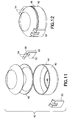
- FIG. 11 is an exploded perspective view of a further embodiment of the present disclosure.
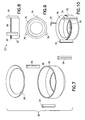
- FIG. 12 is a perspective view of the assembly of the subject finding and stone of FIG. 11.
- FIG. 13 is an exploded perspective view of a finding according to the present disclosure, along with a square stone which is capable of being heated to a soldering temperature.
- FIG. 14 a top perspective view of the assembly of the subject finding and stone of FIG. 13.
- FIG. 15 is a side elevational view of the assembly of the finding and stone as illustrated in FIG. 14.
- FIG. 16 is a perspective view of the assembly of the subject finding and stone of FIG. 15.
- FIG. 17 is an exploded perspective view of another embodiment of a finding according to the present disclosure which is capable of accommodating a square stone.
- FIG. 18 is top perspective view of the assembly of the finding of FIG. 17.
- FIG. 19 is a perspective view of the finding of FIG. 18.
- FIG. 20 is an exploded perspective view of a further embodiment of the present disclosure, which finding is designed to hold a round stone which is capable of being heated to soldering temperatures, and where the finding includes a post.
- FIG. 21 is perspective view of the assembly of the finding and stone of FIG. 20.
- FIG. 22 is an exploded perspective view of another embodiment of the present disclosure, which finding is designed to hold a round stone which is not capable of being heated to soldering temperatures, and where the finding includes a post.
- FIG. 23 is perspective view of the finding of FIG. 22 preparatory to receiving a round stone.
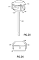
- FIG. 24 is an exploded perspective view of a further embodiment of the present disclosure, which finding is designed to hold a round stone which is not capable of being heated to soldering temperatures, and where the finding includes a post.
- FIG. 25 is perspective view of the assembly of the finding and stone of FIG. 24.
- FIG. 26 is a side elevational view of an assembly of the finding and cabochon stone employing a flat retainer member.
- the subject setting or finding 1 comprises a cylindrical frame 12 for receiving a gemstone and a plurality of prongs 14 which include bent portions 15 for gripping of the stone 10.
- the cylindrical frame 12 includes an annular sidewall 16 and an open bottom or base, designated by the numeral 18, defining a cavity for receiving the gemstone.
- the aperture defining by the base 18 can be of any size and may vary in accordance with the stone selected for a particular setting.
- An upper peripheral edge 20 of the cylindrical frame substantially corresponds to an outer diameter of the round stone 10.
- the prongs 14 are soldered to the sidewall 16 of the cylindrical frame 12, as shown in FIGS. 2 and 3, with the prongs 14 being equally spaced about the perimeter of the cylindrical frame 12.
- the stone 10 rests on the upper peripheral edge 20 of the cylindrical frame 12 of the setting, with the bent portions 15 of the prongs 14 engaging and tightly holding the stone 10 to the finding.
- the peripheral portion 11 of the stone 10, e.g. a girdle, is fully exposed, as is the top portion of the stone 10, other than for the small protrusions of the bent portions 15 of the prongs 14. Accordingly, maximum exposure of the stone 10 is effected, thereby resulting in an aesthetically pleasing assembly of the stone and the subject finding.
- the frame 12 may be formed from any precious or non-precious metal by any known metal forming process, e.g., a stamping process, to correspond to the shape of the gemstone to be set, e.g., round, oval, square, triangle, emerald, pear, marquise, heart, etc..
- Each prong 14 has a generally square cross-sectional configuration, of approximate one half millimeter on each side, and is preferably made of the same metal or material as is the cylindrical frame 12, e.g. gold, silver, platinum, etc..
- the prongs are manufactured as a generally square wire which is cut into desired lengths.
- the wire includes a layer of solder around and along an entire length of the wire.
- the color of solder will approximately match the color of the setting, i.e., the frame and prongs.
- the wire may be of other shapes to effect different looks of the setting.
- the wire may be circular and cut to the desired length. The cut lengths of the wire will vary and will depend on the size and/or the shape of the stone to be set.
- the stone 10 is placed on the cylindrical frame 12 so as to engage the upper peripheral edge 20, and because of this configuration, the stone 10 is essentially self-centered.
- the cylindrical frame 12, the stone 10, and the prongs 14 are arranged as shown in FIG. 2 and placed in a suitable jig for holding the assembly. As shown in FIG. 2, a lower portion 13 of the prong will be placed in contact with the sidewall 16 and the bent portion 15 of the prong will be placed in contact with an upper portion of the stone above the peripheral portion 11 of the stone 10.
- the finding assembly will then be subjected to a sufficient predetermined temperature, e.g., on the order of 1,400°F, so as to solder the prongs 14 to the frame 12, e.g., to allow the solder to reflow and form a joint between the prongs and the frame, and to provide a sturdy grip by the bent portions 15 of the prongs 14 against the upper portion of the stone, thereby resulting in the assembled stone and finding as shown in FIG. 3.
- a sufficient predetermined temperature e.g., on the order of 1,400°F
- the gemstone 10 employed must be able to withstand high temperatures without becoming damaged.
- the lowest tolerable temperature of the gemstone must be at least a predetermined amount of degrees higher than the melting point, or reflow temperature, of the solder being employed.
- the melting point of the solder must be lower than a melting point of the metal of frame 12.
- a retainer member is employed to center the gemstone received in the frame.
- a retainer member is generally designated by reference numeral 22.
- the retainer member 22 is annular shaped and has an outer circumference 24 corresponding to the upper peripheral edge 20 of the frame 12.
- the retainer member 22 is formed with a layer of solder for bonding the retainer member 22 to the frame.
- the setting shown in FIGS. 4-6 will be assembled as described above with the further step of disposing the retainer member 22 on the frame 12 before disposing the stone on the frame.
- a gemstone having a girdle circumference 11 less than the circumference of the frame may be used in the setting 1 of the present disclosure.
- the retainer member may be employed depending on the size and/or shape of the stone to be set, i.e., a shape of the retainer member will substantially correspond to the shape of the stone, e.g., square, oval, etc..
- the retainer member is configured with an inwardly down-sloping angle best suited for faceted stones.
- Another exemplary retainer member will include a flat annular ring 130 which will be disposed on the upper peripheral edge 20 of the frame 12 as shown in FIG. 26.
- the stone 132 will rest on the retainer member 130 whereby virtually no part of the stone 132 will be disposed in the frame 12 to effect full exposure of the stone.
- Such a retainer member might be employed with a cabochon stone.
- the prongs 134 will securely hold the stone in place as described in the various embodiments.
- the setting 30 is designed to be used with a stone that is not capable of being subjected to elevated temperatures for soldering the prongs 34 to the frame 32.
- the finding 30 includes a retainer member 36 which is soldered to the upper peripheral edge 38 of the frame 32, at the same time that the prongs 34 are soldered to the frame 32.
- the resulting finding 30 is illustrated in FIGS. 8, 9 and 10.
- the prongs 34 are straight and are not formed with bent portions as in the embodiment of FIG. 1.
- the straight leg prongs 34 are soldered to the frame 32 without the bent portions so a gemstone may be set in the frame after the soldering has taken place. Since the prongs 34 have solder on all sides, the prongs may be placed in the jig with any side of the prong coming into contact with the frame 32, allowing quick and easy placement of the components into the jig without having to determine which side of the prong has solder disposed on it.
- a stone is placed on the retainer ring 36, and is self-centered, after which the prongs 34 are bent inwardly to firmly grip the stone.
- the prongs may be bent to grip the stone by a modified drill press such as the DP-30 Drill Press commercially available from The Foredom Electric Company of Bethel, Connecticut.
- the resulting setting with gemstone in place is similar to that shown in FIG. 6.
- the setting 40 includes a cylindrical frame 42 including a sidewall 44 and a bottom or base 46 with an aperture, a retainer member 48 and two prongs 50.
- Each prong 50 includes a generally rectangular portion 52 for mating with the sidewall 44 and two prong members 54 for securely gripping a gemstone received in the frame 42.
- the rectangular portion 52 will be curved to substantially correspond to the curvature of sidewall 44 so when mated the rectangular portion 52 is in full contact with sidewall 44 which in turn will form a stronger joint during the soldering step.
- the prong members 54 include a bent portion 56 and will be utilized with gemstones that can withstand the high temperatures of the soldering process.
- the prongs 50 can be manufactured with straight prong members 54 wherein the prongs 50 will be soldered to the frame 42 without the gemstone in place and, after the gemstone is received in the setting, the prong members 54 will be bent inward to secure the gemstone. In either case, the resulting setting with gemstone in place is illustrated in FIG. 12.
- a further embodiment of the subject setting 60 is designed to accommodate square stones, and includes a square-shaped frame 62 and a plurality of prongs 64.
- Each of the plurality of prongs 64 includes a bent portion 66.
- a square stone is placed on the upper peripheral rim 68 of the frame 62 so as to be self-centered, after which the frame 62 and the prongs 64 are placed in a suitable jig.
- the assembly is subjected to a high temperature for soldering the prongs 64 to the frame 62.
- the assembly of the prongs 64 to the frame 62 is illustrated in FIGS. 14-16.
- the prongs 70 are straight as illustrated in FIGS. 17-19.
- a retainer member 72 is employed. Although shown as having an inwardly down-sloping angle, the retainer member 72 may be flat for a stone with a flat bottom so no portion of the gemstone is inside the frame and is therefore fully exposed.
- the frame 62, prongs 70 and retainer member 72 are placed in a suitable jig, after which the assembly is subjected to a high temperature for soldering the prongs 70 and retainer member 72 to the frame 62. Thereafter, a square stone is placed on the upper peripheral rim 68 of the frame 62 where the retainer member 72 sits so as to be self-centered and the prongs 70 are bent inwardly to grip the stone by a suitable drill press as described above.
- the setting 80 includes a generally cylindrically shaped frame 82, a plurality of prongs 88 and a retainer member 90.
- the frame 82 includes a sidewall 84 and a spherical shaped bottom 86.
- Each of the plurality of prongs 88 includes a bent portion 92.
- the setting further includes a post 94 which will be soldered to an underside of the bottom 86 of the frame 82.
- the frame 82 and retainer member 90 are placed in a suitable jig, after which a stone 96 is placed on the upper peripheral rim of the retainer member 90 so as to be self-centered.
- the prongs 88 are then placed in the jig, after which the assembly is subjected to a high temperature for soldering the prongs 88 and retainer member 90 to the frame 82.
- the post 94 is soldered to the frame 82.
- the assembly of the prongs 88 to the frame 82 with stone in place is illustrated in FIG. 21.
- FIGS. 22 and 23 illustrate another embodiment of the setting or finding of the present disclosure, which embodiment is designated by the numeral 100.
- Setting 100 is also designed to accommodate stones which are not capable of being subjected to elevated soldering temperatures, with the setting 100 including a frame 102, retaining member or ring 104 and straight leg prongs 106, as well as a post 108.
- the retainer member 104 and prongs 106 will be provided with a layer of solder colored to match the color of the frame 102.
- the frame 102, retainer member 104, prongs 106 and post 108 will be assembled in a suitable jig and subjected to an elevated temperature to allow the solder to reflow and join the components together.
- the assembled setting 100 is illustrated in FIG. 23.
- a stone is placed on the frame 102, and then the prongs 106 are bent radially inwardly to grip the stone as described above.
- the setting 110 includes a generally cylindrically shaped frame 112, a plurality of prongs 114 and a retainer member 116.
- the frame 112 includes at least one sidewall 118 and a spherical shaped bottom 120.
- the sidewall 118 includes at least two cutouts 122 for exposing a bottom portion of the gemstone.
- the frame 112 has three cutouts resulting in three sidewalls 118. It is to be appreciated the number of cutouts and sidewalls may vary based on the size and shape of the gemstone.
- the setting further includes a post 126 which will be soldered to an underside of the bottom 120 of the frame 112.
- the frame 112 In assembling the setting 110, the frame 112, prongs 114, retainer member 116 and post 126 are placed in a suitable jig, after which the assembly is subjected to a high temperature for soldering the prongs 114, retainer member 116 and post 126 to the frame 112. After a gemstone is disposed on the retainer member 116, the prongs 114 will be bent by a suitable drill press at a portion of the prong above the girdle of the gemstone to secure the gemstone in place.
- the assembly of the prongs 114 to the frame 112 is illustrated in FIG. 25. In other embodiments, the assembly could be made without the post 126 which could be soldered to the frame at a later time by applying solder paste to one end of the post.
- the setting 110 may employ prongs with an upper bent portion as described in the various embodiments above.
- the frame 112, retainer member 116 and post 126 are placed in a suitable jig, after which a stone 128 is placed on the upper peripheral rim of the retainer member 116 so as to be self-centered.
- the prongs with upper bent portions (not shown) are then placed in the jig, after which the assembly is subjected to a high temperature for soldering the prongs, retainer member 116 and post 126 to the frame 112.
- the assembly of the prongs to the frame 112 with stone in place is illustrated in FIG. 25. As can be seen, whether straight prongs or bent prongs are used, the resulting setting after gemstone placement is the same.
- the resulting finding ensures maximum exposure of the stone including maximum exposure of the peripheral side edges of the stone, as well as providing an inexpensive, but sturdy finding for griping of the stone.
Landscapes
- Adornments (AREA)
Applications Claiming Priority (1)
| Application Number | Priority Date | Filing Date | Title |
|---|---|---|---|
| US11/330,945 US20070089457A1 (en) | 2005-10-20 | 2006-01-12 | Jewelry setting |
Publications (1)
| Publication Number | Publication Date |
|---|---|
| EP1808090A1 true EP1808090A1 (de) | 2007-07-18 |
Family
ID=37890739
Family Applications (1)
| Application Number | Title | Priority Date | Filing Date |
|---|---|---|---|
| EP07290012A Withdrawn EP1808090A1 (de) | 2006-01-12 | 2007-01-04 | Schmucksteinbefestigung |
Country Status (2)
| Country | Link |
|---|---|
| US (1) | US20070089457A1 (de) |
| EP (1) | EP1808090A1 (de) |
Families Citing this family (7)
| Publication number | Priority date | Publication date | Assignee | Title |
|---|---|---|---|---|
| ITMI20080208A1 (it) * | 2008-02-11 | 2009-08-12 | Antonio Corvino | Struttura di gioiello con pietra preziosa. |
| US20090229307A1 (en) * | 2008-03-11 | 2009-09-17 | Wing Cheuk Kwan | Method of decorating an article |
| KR101161986B1 (ko) | 2010-09-30 | 2012-07-03 | 이조원 | 머리 장식용 비즈 및 그 제조방법 |
| RU2498750C1 (ru) * | 2012-10-03 | 2013-11-20 | Виктор Владимирович Моисейкин | Закрепка для камней в ювелирном изделии |
| USD860036S1 (en) * | 2017-04-10 | 2019-09-17 | H.K. Designs Inc. | Precious stone jewelry setting |
| USD899964S1 (en) * | 2017-05-22 | 2020-10-27 | H. K. Designs Inc. | Precious stone jewelry setting |
| USD891977S1 (en) * | 2017-05-22 | 2020-08-04 | H. K. Designs Inc. | Precious stone jewelry setting |
Citations (4)
| Publication number | Priority date | Publication date | Assignee | Title |
|---|---|---|---|---|
| US6003335A (en) * | 1999-05-26 | 1999-12-21 | Orion Diamond Inc. | Multi-stone center setting for diamonds and gemstones |
| US6112551A (en) * | 1998-09-09 | 2000-09-05 | Irikura Precious Metal Craft Ltd. | Setting metallic parts for setting a facet cut precious stone |
| US20020166337A1 (en) * | 2001-05-09 | 2002-11-14 | Jacob Cohen | Round gemstone arrangements with settings |
| US20050210919A1 (en) * | 2004-03-26 | 2005-09-29 | Paula Klecka | Lattice structure forming a surface of gemstones |
Family Cites Families (12)
| Publication number | Priority date | Publication date | Assignee | Title |
|---|---|---|---|---|
| US165722A (en) * | 1875-07-20 | Improvement in setting gems | ||
| US1604013A (en) * | 1925-09-12 | 1926-10-19 | Bausch Albert | Flexible-bracelet box |
| US2584207A (en) * | 1950-07-25 | 1952-02-05 | Holl Charles | Gem setting and articles of jewelry made therefrom |
| US3014354A (en) * | 1958-02-25 | 1961-12-26 | Mccary Jewelers Inc | Setting for detachably or permanently mounting a stone |
| US4292818A (en) * | 1979-09-17 | 1981-10-06 | Jean Vitau | Setting and method for mounting precious stones and the like therein |
| JPS6417605A (en) * | 1987-07-13 | 1989-01-20 | Fuaburikanto & Sons Inc M | Double-face accessory set |
| US4914930A (en) * | 1988-07-12 | 1990-04-10 | Bielka Robert B | Jeweled mesh for jewelry |
| US5357770A (en) * | 1992-04-10 | 1994-10-25 | Lanyi Carolyn H | Jewelry with interchangeable ornamental members |
| US5636421A (en) * | 1994-11-18 | 1997-06-10 | Brams; Peter | Method of manufacturing an article of jewelry having faux pave look |
| US6434805B2 (en) * | 1999-03-12 | 2002-08-20 | L.I.D. Ltd. | Method of making a heart-shaped diamond |
| US6298689B1 (en) * | 2000-08-21 | 2001-10-09 | Gramercy Jewelry Manufacturing Corp. | Jewelry setting |
| US6729159B2 (en) * | 2002-07-16 | 2004-05-04 | Laura Jeanene Rose | Interchangeable jewelry system |
-
2006
- 2006-01-12 US US11/330,945 patent/US20070089457A1/en not_active Abandoned
-
2007
- 2007-01-04 EP EP07290012A patent/EP1808090A1/de not_active Withdrawn
Patent Citations (4)
| Publication number | Priority date | Publication date | Assignee | Title |
|---|---|---|---|---|
| US6112551A (en) * | 1998-09-09 | 2000-09-05 | Irikura Precious Metal Craft Ltd. | Setting metallic parts for setting a facet cut precious stone |
| US6003335A (en) * | 1999-05-26 | 1999-12-21 | Orion Diamond Inc. | Multi-stone center setting for diamonds and gemstones |
| US20020166337A1 (en) * | 2001-05-09 | 2002-11-14 | Jacob Cohen | Round gemstone arrangements with settings |
| US20050210919A1 (en) * | 2004-03-26 | 2005-09-29 | Paula Klecka | Lattice structure forming a surface of gemstones |
Also Published As
| Publication number | Publication date |
|---|---|
| US20070089457A1 (en) | 2007-04-26 |
Similar Documents
| Publication | Publication Date | Title |
|---|---|---|
| US5671613A (en) | Gem setting having notched prongs | |
| JPH0731695Y2 (ja) | 装身具 | |
| US20160316864A1 (en) | Article of jewelry and /or of lapidary work | |
| US5765398A (en) | Method and apparatus for assembling stones in jewelry | |
| US4936115A (en) | Gem setting | |
| EP2172123A2 (de) | Schmuckstückanordnung | |
| US11766100B1 (en) | Interchangeable piece or set of jewelry | |
| EP1808090A1 (de) | Schmucksteinbefestigung | |
| US5285659A (en) | Method and apparatus for setting stones in jewelry | |
| US6453701B1 (en) | Multi-part jewelry setting | |
| US5680776A (en) | Metal mount for cut jewels and accessories | |
| US20050044890A1 (en) | Gemstone mount assemblies, jewelry pieces and methods for forming the same | |
| US20190373990A1 (en) | Method of Visually Accenting a Piece of Jewelry | |
| JPH03112502A (ja) | カット済宝石用取付金具および装身具 | |
| JP5461164B2 (ja) | 装身具 | |
| US6105393A (en) | Gem stone setting for articles of jewelry | |
| US5855048A (en) | Jeweler's stone setting tool | |
| CN209769247U (zh) | 组合式镶座及饰品 | |
| JP6917098B1 (ja) | 宝石支持台および装飾具 | |
| KR102153868B1 (ko) | 연결고리가 일체로 성형되는 귀걸이 고정구 제조 방법 | |
| JP2003248068A (ja) | 装飾品の製造方法、装飾材取付用工具、装飾材取付固定部構造、装飾品及び時計 | |
| KR101496736B1 (ko) | 원형 형태의 스톤 고정방법 및 그 방법을 통해 생산된 장신구 | |
| JP2007268242A (ja) | 装飾石の固着方法および宝飾品 | |
| JP2003088408A (ja) | 装身具用部材 | |
| KR960005947B1 (ko) | 장신구 |
Legal Events
| Date | Code | Title | Description |
|---|---|---|---|
| PUAI | Public reference made under article 153(3) epc to a published international application that has entered the european phase |
Free format text: ORIGINAL CODE: 0009012 |
|
| AK | Designated contracting states |
Kind code of ref document: A1 Designated state(s): AT BE BG CH CY CZ DE DK EE ES FI FR GB GR HU IE IS IT LI LT LU LV MC NL PL PT RO SE SI SK TR |
|
| AX | Request for extension of the european patent |
Extension state: AL BA HR MK YU |
|
| STAA | Information on the status of an ep patent application or granted ep patent |
Free format text: STATUS: THE APPLICATION HAS BEEN WITHDRAWN |
|
| 18W | Application withdrawn |
Effective date: 20080109 |