EP1808531A1 - Vorrichtung zur Anbringung von Sensoren bzw. Schaltmitteln in Gleisanlagen - Google Patents
Vorrichtung zur Anbringung von Sensoren bzw. Schaltmitteln in Gleisanlagen Download PDFInfo
- Publication number
- EP1808531A1 EP1808531A1 EP06450180A EP06450180A EP1808531A1 EP 1808531 A1 EP1808531 A1 EP 1808531A1 EP 06450180 A EP06450180 A EP 06450180A EP 06450180 A EP06450180 A EP 06450180A EP 1808531 A1 EP1808531 A1 EP 1808531A1
- Authority
- EP
- European Patent Office
- Prior art keywords
- plug
- housing
- cover
- cable
- adapter
- Prior art date
- Legal status (The legal status is an assumption and is not a legal conclusion. Google has not performed a legal analysis and makes no representation as to the accuracy of the status listed.)
- Granted
Links
Images



Classifications
-
- B—PERFORMING OPERATIONS; TRANSPORTING
- B61—RAILWAYS
- B61L—GUIDING RAILWAY TRAFFIC; ENSURING THE SAFETY OF RAILWAY TRAFFIC
- B61L1/00—Devices along the route controlled by interaction with the vehicle or train
- B61L1/02—Electric devices associated with track, e.g. rail contacts
-
- E—FIXED CONSTRUCTIONS
- E01—CONSTRUCTION OF ROADS, RAILWAYS, OR BRIDGES
- E01B—PERMANENT WAY; PERMANENT-WAY TOOLS; MACHINES FOR MAKING RAILWAYS OF ALL KINDS
- E01B26/00—Tracks or track components not covered by any one of the preceding groups
Definitions
- the invention relates to a device for mounting sensors or switching means in track systems with a housing which receives the or the sensors or switching means, by means of a bracket in the rail area is attachable and from the at least one connecting cable of the sensors or switching means to outside Gleis Symposiumes provided connection points is led out.
- Sensors and switching means are preferably mounted in the vicinity of the rail head within the track, so on the side facing the other rail side.
- fastening and adjustment fasteners are known to run through holes in the rail web screws.
- so-called rail claws used, which detect the two edges of the rail foot from opposite sides and of which one is adjustable via one or two clamping screws.
- the fasteners ie, for. B. the rail claw in case of need also height adjustable connected and where the housing - which can also be a plastic molding - is removably attached with other screws.
- the cable is led out on the side facing away from the rail and then under the rail to a distance from the rail provided for connecting points that either process the sensor signals themselves or pass processed signals to a central office. In the track area, the cable is sunk into the bedding. To ensure a safe connection of the sensors etc. to the cable, it is known to make permanent connections between the cable and sensor circuit and to pour the joint waterproof in the sensor housing.
- the object of the invention is to eliminate the above-mentioned difficulties and disadvantages and to provide a device which substantially facilitates the assembly and disassembly of the sensors in the rail area.
- a plug connection is provided for the cable
- the plug socket is housed within the housing in a plug and in its connection position at least partially receiving recess and that a cover is provided for the plug, in its mounting position on the housing fixed the plug in its connection position.
- the inventive design a secure connection of the sensors and switching means is guaranteed to the cable despite the use of the connector, the connector is sufficiently protected by the particular configuration with placement in a housing recess and by the cover. It is possible to disconnect cables and housings prior to assembly or disassembly, so that only the cable with the plug under the rail is fürzufädeln. Assembly and disassembly of the housing to or from the bracket are no longer hindered by the cable.
- the plug or an adapter receiving it on the outer shell on corresponding side wall parts of the example prismatic housing recess adapted guide surfaces and is provided on the outside with Gegenandrückanni for the cover.
- the use of an adapter has the advantage here that it can be made relatively large and stable and different plugs can be used with appropriate adapter receptacle, the plug itself can be built small and preferably also commercial plug can be used.
- the controls themselves are relieved of inertial forces emanating from vibrations and shocks in the connection area of the cable.
- the plug or adapter carries an outlet pipe or a grommet for leading out the cable and the cover has an adapted downwardly open plug-in opening to its or their implementation.
- additional means for sealing and fixing the cable can be provided on the cable sheath.
- the outlet tube or spout also protects the cable against damage when entering, etc.
- the cover can still be easily assembled and disassembled because of the special design of the slip-on.
- the cover with self-locking Allen screws whose head is sunk into it, attached to the housing.
- the cover forms a shaped piece with up to its further front area curved sloping upper edge and that on both sides of its mounting area on the housing this curved upper edge optically and in the form of extending strips are provided, the undersides additionally be used as a support on a support plate holding the housing, which then has an upwardly open, in this region of the preferably rounded outline of the cover corresponding cutout.
- the rounding makes it difficult to enter and the overall kit receives a largely smooth, closed outer shape, at least from above.
- a support plate 2 is attached to the housing 3 of a sensor by means of a rail claw.
- the rail claw has a one-piece shaped, via a nut 2 on a lag screw 4 adjustable claw 5 and a second jaw 6 of a retaining piece 7 and two adjustable on the Schienenfußbreite jaws 8.
- the support plate 2 is by means of engaging in slots 9 screws 10 opposite the holding piece 7 according to provided locking the height adjustable.
- the housing 3 of the sensor is fastened with screws 11, the inner ends of which are fixed in the support plate 2 by compression points 11 a, and rail-side self-locking nuts 12 are fastened to the support plate 2.
- a housing recess 13 is provided, protruding from the central part of a female connector 14, which forms the one part of a terminal connection for or housed in the housing 3 sensors.
- an adapter 15 is provided, which has in the housing recess 13 matching mating surfaces, in the inserted state full receptacle in the housing recess 13, where it is guided with guide surfaces and carries a discharge spout 16 for the cable leading to the plug.
- the adapter 15 and thus held on it plug is held by a cover 17 in its operating position and thus the coupling position of the plugger.
- the cover 17 has an adapted to the front edges of the adapter 15 downwardly open plug-18 and is secured by means of self-locking Allen screws 19, whose heads are recessed in the insertion 20, the housing 3, where these screws engage in threaded holes 21.
- the cover 17 engages with curves 22 in a corresponding section 23 of the support plate 2, so that the cover is aligned in this area with its outside with the outside of the support plate 2.
- In the upper part of the cover 17 has a curved sloping edge portion 24 which is extended to the two sides by integrally formed on the housing 3 bars 25, the lower sides of these strips 25 can rest on the upper edge of the support plate 2.
Landscapes
- Engineering & Computer Science (AREA)
- Architecture (AREA)
- Civil Engineering (AREA)
- Structural Engineering (AREA)
- Automation & Control Theory (AREA)
- Mechanical Engineering (AREA)
- Arrangements For Transmission Of Measured Signals (AREA)
- Alarm Systems (AREA)
- Casings For Electric Apparatus (AREA)
- Connector Housings Or Holding Contact Members (AREA)
- Details Of Connecting Devices For Male And Female Coupling (AREA)
- Connections Arranged To Contact A Plurality Of Conductors (AREA)
- Switches That Are Operated By Magnetic Or Electric Fields (AREA)
Abstract
Description
- Die Erfindung bezieht sich auf Vorrichtung zur Anbringung von Sensoren bzw. Schaltmitteln in Gleisanlagen mit einem Gehäuse, das den bzw. die Sensoren oder Schaltmittel aufnimmt, mittels einer Halterung im Schienenbereich anbringbar ist und aus dem wenigstens ein Anschlußkabel der Sensoren bzw. Schaltmittel zu außerhalb des Gleisbereiches vorgesehenen Anschlußstellen herausgeführt ist.
- Sensoren und Schaltmittel, z. B. Radsensoren, werden bevorzugt in der Nähe des Schienenkopfes innerhalb des Geleises, also an der zur anderen Schiene weisenden Seite angebracht. Für die Befestigung und Einstellung sind Befestigungen mit durch Bohrungen des Schienensteges geführten Schrauben bekannt. Derzeit werden bevorzugt aber z. B. aus der
US 5 628 579 A1 bekannte, sogenannte Schienenklauen verwendet, die die beiden Ränder des Schienenfußes von gegenüberliegenden Seiten her erfassen und von denen die eine über eine oder zwei Spannschrauben verstellbar ist. Als Halterung werden häufig Tragplatten verwendet, die mit den Befestigungsmitteln, also z. B. der Schienenklaue im Bedarfsfall auch höheneinstellbar verbunden sind und an denen das Gehäuse - das auch ein Kunststoffformteil sein kann - mit weiteren Schrauben abnehmbar befestigt ist. Das Kabel wird an der von der Schiene abweisenden Seite heraus und dann unter der Schiene zu in größerem Abstand von der Schiene vorgesehenen Anschlußstellen geführt, die entweder die Sensorsignale selbst weiterverarbeiten oder aufbereitete Signale zu einer Zentrale weiterleiten. Im Gleisbereich wird das Kabel jeweils in die Bettung versenkt. Zur Gewährleistung eines sicheren Anschlusses der Sensoren usw. an das Kabel ist es bekannt, unlösbare Verbindungen zwischen Kabel und Sensorschaltung herzustellen und die Verbindungsstelle wasserdicht in das Sensorgehäuse einzugießen. - Diese Technik hat sich im Hinblick auf die enormen Schwingungen und Stöße, denen ein derartiges Gleisschaltmittel ausgesetzt ist, bewährt. Allerdings ergeben sich beträchtliche Schwierigkeiten, wenn es notwendig wird die Sensoren samt ihrem Gehäuse zu ersetzen oder abzubauen. Ein Abbau der gesamten Halterung und der Sensoren ist überdies notwendig, wenn Wartungsarbeiten am Geleise selbst durchzuführen sind. Dies ist unter anderem beim Einsatz eines Schleifzuges oder von Gleisstopfmaschinen der Fall. Die notwendigen Arbeiten beim Abbau und beim neuerlichen Einbau werden besonders durch das am Gehäuse hängende Kabel behindert, wobei bei größeren Abständen zur Anschlußstelle das dann von der Halterung abgenommene Gehäuse unter der Schiene durchgefädelt werden muß. Es ist zu bedenken, daß solche Arbeiten im Gefahrenbereich des Gleises durchzuführen sind und im Sinne der Sicherheit und Dauer der Streckensperre grundsätzlich so kurz wie möglich dauern sollten. Auch beim Normalbetrieb ergeben sich besonders für das Kabel Gefahren der Beschädigung, z. B. wenn das Sensorgehäuse von einem Schienengeher betreten wird, der dann möglicherweise abrutscht und auf das Kabel steigt.
- Aufgabe der Erfindung ist es, die oben aufgezeigten Schwierigkeiten und Nachteile zu beseitigen und eine Vorrichtung zu schaffen, welche die Montage und Demontage der Sensoren im Schienenbereich wesentlich erleichtert.
- Diese Aufgabe wird dadurch gelöst, daß für das Kabel eine Steckverbindung vorgesehen ist, deren Steckerbuchse innerhalb des Gehäuses in einer auch den Stecker in seiner Anschlußstellung wenigstens teilweise aufnehmenden Vertiefung untergebracht ist und daß für den Stecker eine Abdeckung vorgesehen ist, die in ihrer Befestigungsstellung am Gehäuse den Stecker in seiner Anschlußstellung fixiert.
- Durch die erfindungsgemäße Ausführung wird trotz der Verwendung der Steckverbindung ein sicherer Anschluß der Sensoren und Schaltmittel an das Kabel gewährleistet, wobei die Steckverbindung durch die besondere Ausgestaltung mit Unterbringung in einer Gehäusevertiefung und durch die Abdekkung ausreichend geschützt ist. Es wird möglich, Kabel und Gehäuse vor der Montage bzw. Demontage zu trennen, so daß nur das Kabel mit dem Stecker unter der Schiene durchzufädeln ist. Montage und Demontage des Gehäuses an bzw. von der Halterung werden durch das Kabel nicht mehr behindert.
- Nach einer bevorzugten Weiterbildung weist der Stecker oder ein ihn aufnehmender Adapter am Außenmantel an entsprechende Seitenwandungsteile der zum Beispiel prismatischen Gehäusevertiefung angepaßte Führungsflächen auf und ist außenseitig mit Gegenandrückflächen für die Abdeckung versehen. Die Verwendung eines Adapters hat hier den Vorteil, daß dieser relativ groß und stabil ausgeführt werden kann und verschiedene Stecker mit entsprechender Adapteraufnahme einsetzbar sind, wobei die Stecker selbst klein gebaut werden können und vorzugsweise auch handelsübliche Stecker einsetzbar sind. Damit werden die Steuerelemente selbst von Massenkräften entlastet, die von Schwingungen und Stößen im Anschlußbereich des Kabels ausgehen.
- Nach einer Weiterbildung ist vorgesehen, daß der Stecker bzw. Adapter ein Auslaßrohr oder eine Tülle zur Herausführung des Kabels trägt und die Abdeckung eine angepaßte nach unten offene Aufstecköffnung zu dessen bzw. deren Durchführung aufweist. Im Auslaßrohr bzw. der Tülle können zusätzliche Mittel zur Abdichtung und zur Befestigung des Kabels am Kabelmantel vorgesehen werden. Bei entsprechend starrer Ausführung schützt das Auslaßrohr bzw. die Tülle auch das Kabel gegen Beschädigungen beim Betreten usw.. Die Abdeckung kann wegen der besonderen Ausführung der Aufstecköffnung trotzdem leicht montiert und demontiert werden.
- Es ist anzustreben, das Gehäuse zumindest an der Oberseite und im oberen Frontseitenbereich von Vorsprüngen freizuhalten. Aus diesem Grund ist nach einer bevorzugten Ausführung auch die Abdeckung mit selbstsichernden Imbusschrauben, deren Kopf in sie versenkt ist, am Gehäuse befestigt.
- Nach einer Ergänzung der zuletzt genannten Maßnahme ist vorgesehen, daß die Abdeckung ein Formstück mit bis zu ihrem weiteren frontseitigen Bereich gewölbt abfallendem oberen Rand bildet und daß beidseits ihres Anbringungsbereiches am Gehäuse diesen gewölbten oberen Rand optisch und in der Form verlängernde Leisten vorgesehen sind, deren Unterseiten zusätzlich als Abstützung auf einer das Gehäuse haltenden Tragplatte verwendbar sind, die dann einen nach oben offenen, in diesem Bereich der vorzugsweise gerundeten Umrißform der Abdeckung entsprechenden Ausschnitt aufweist. Die Abrundung erschwert das Betreten und der Gesamtbausatz erhält zumindest von oben gesehen eine weitgehend glatte, geschlossene Außenform.
- Weitere Einzelheiten und Vorteile des Erfindungsgegenstandes entnimmt man der nachfolgenden Zeichnungsbeschreibung.
- In der Zeichnung ist der Erfindungsgegenstand beispielsweise veranschaulicht. Es zeigen:
- Fig. 1
- eine an einer Schiene angebrachte erfindungsgemäße Vorrichtung im Schaubild,
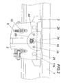
- Fig. 2
- die Vorrichtung nach Fig. 1 in Vorderansicht und im Schnitt für ein Detail,
- Fig. 3
- die Anschlußelemente der Vorrichtung in explodierter Darstellungsweise und
- Fig. 4
- einen Querschnitt zu den vorhergehenden Figuren.
- An einer Schiene 1 ist eine Tragplatte 2 für das Gehäuse 3 eines Sensors mittels einer Schienenklaue befestigt. Die Schienenklaue besitzt eine einteilig geformte, über eine Mutter 2 auf einer Zugschraube 4 verstellbare Klaue 5 und eine zweite Klaue 6 aus einem Haltestück 7 und zwei auf die Schienenfußbreite einstellbaren Backen 8. Die Tragplatte 2 ist mit Hilfe von in Langlöcher 9 eingreifenden Schrauben 10 gegenüber dem Haltestück 7 nach vorgesehenen Verrastungen der Höhe nach einstellbar. Die konstruktiven Einzelheiten der beschriebenen Klauenkonstruktion sind Gegenstand einer parallelen Anmeldung.
- Das Gehäuse 3 des Sensors ist mit Schrauben 11, deren innere Enden in der Tragplatte 2 durch Verpressungsstellen 11a fixiert sind und schienenseitige selbsthemmende Muttern 12 an der Tragplatte 2 befestigt. Frontseitig ist eine Gehäusevertiefung 13 vorgesehen, aus deren Mittelteil eine Steckerbuchse 14 vorragt, die den einen Teil einer Anschlußverbindung für den oder die im Gehäuse 3 untergebrachten Sensoren bildet. Für einen Gegenstecker mit Kabelanschluß ist ein Adapter 15 vorgesehen, der in die Gehäusevertiefung 13 passende Gegenführungsflächen aufweist, im eingesetzten Zustand volle Aufnahme in der Gehäusevertiefung 13 findet, dort mit Führungsflächen geführt ist und eine Auslastülle 16 für das zum Stecker führende Kabel trägt. Der Adapter 15 und damit der an ihm gehaltene Stecker wird durch eine Abdekkung 17 in seiner Einsatzstellung und damit der Kupplungsstellung des Stekkers festgehalten. Die Abdeckung 17 besitzt einen an die Vorderränder des Adapters 15 angepaßte nach unten offene Aufstecköffnung 18 und wird mit Hilfe selbstsichernder Imbusschrauben 19, deren Köpfe in die Einstecköffnungen 20 versenkt sind, am Gehäuse 3 befestigt, wo diese Schrauben in Gewindelöcher 21 eingreifen. In der eingesetzten Stellung greift die Abdeckung 17 mit Rundungen 22 in einen entsprechenden Ausschnitt 23 der Tragplatte 2 ein, so daß die Abdeckung in diesem Bereich mit ihrer Außenseite mit der Außenseite der Tragplatte 2 fluchtet. Im oberen Bereich hat die Abdeckung 17 einen gewölbt abfallenden Randbereich 24, der nach den beiden Seiten hin durch an das Gehäuse 3 angeformte Leisten 25 verlängert ist, wobei die Unterseiten dieser Leisten 25 am oberen Rand der Tragplatte 2 aufliegen können.
Claims (4)
- Vorrichtung zur Anbringung von Sensoren bzw. Schaltmitteln in Gleisanlagen mit einem Gehäuse, das den bzw. die Sensoren oder Schaltmittel aufnimmt, mittels einer Halterung im Schienenbereich anbringbar ist und aus dem wenigstens ein Anschlußkabel der Sensoren bzw. Schaltmittel zu außerhalb des Gleisbereiches vorgesehenen Anschlußstellen herausgeführt ist, dadurch gekennzeichnet, daß für das Kabel eine Steckverbindung (14, 15) vorgesehen ist, deren Steckerbuchse (14) innerhalb des Gehäuses (3) in einer auch den Stecker (15) in seiner Anschlußstellung wenigstens teilweise aufnehmenden Vertiefung (13) untergebracht ist und daß für den Stecker (15) eine Abdeckung (17) vorgesehen ist, die in ihrer Befestigungsstellung am Gehäuse (3) den Stecker (15) in seiner Anschlußstellung fixiert.
- Vorrichtung nach Anspruch 1, dadurch gekennzeichnet, daß der Stecker oder ein ihn aufnehmender Adapter (15) am Außenmantel an entsprechende Seitenwan-dungsteile der zum Beispiel prismatischen Gehäusevertiefung (13) angepaßte Führungsflächen aufweist und außenseitig mit Gegenandrückflächen für die Abdeckung (17) versehen ist.
- Vorrichtung nach Anspruch 1 oder 2, dadurch gekennzeichnet, daß der Stecker bzw. Adapter (15) ein Auslaßrohr (16) zur Herausführung des Kabels trägt und die Abdeckung (17) eine angepaßte nach unten offene Aufstecköffnung (18) zu dessen Durchführung aufweist.
- Vorrichtung nach einem der Ansprüche 1 bis 3, dadurch gekennzeichnet, daß die Abdeckung (17) mit selbstsichernden Imbusschrauben (19), deren Kopf in sie versenkt ist, am Gehäuse (3) befestigt ist.
Priority Applications (3)
| Application Number | Priority Date | Filing Date | Title |
|---|---|---|---|
| SI200630251T SI1808531T1 (sl) | 2005-12-14 | 2006-12-14 | Naprava za pritrditev senzorjev oz. stikalnih priprav na ĺ˝elezniĺ ke tire |
| PL06450180T PL1808531T3 (pl) | 2005-12-14 | 2006-12-14 | Urządzenie do mocowania czujników, względnie środków przełączających w układach torowych |
| AT06450180T ATE420244T1 (de) | 2005-12-14 | 2006-12-14 | Vorrichtung zur anbringung von sensoren bzw. schaltmitteln in gleisanlagen |
Applications Claiming Priority (1)
| Application Number | Priority Date | Filing Date | Title |
|---|---|---|---|
| AT0199105A AT502019B1 (de) | 2005-12-14 | 2005-12-14 | Vorrichtung zur anbringung von sensoren bzw. schaltmitteln in gleisanlagen |
Publications (2)
| Publication Number | Publication Date |
|---|---|
| EP1808531A1 true EP1808531A1 (de) | 2007-07-18 |
| EP1808531B1 EP1808531B1 (de) | 2009-01-07 |
Family
ID=37591970
Family Applications (1)
| Application Number | Title | Priority Date | Filing Date |
|---|---|---|---|
| EP06450180A Active EP1808531B1 (de) | 2005-12-14 | 2006-12-14 | Vorrichtung zur Anbringung von Sensoren bzw. Schaltmitteln in Gleisanlagen |
Country Status (6)
| Country | Link |
|---|---|
| EP (1) | EP1808531B1 (de) |
| AT (2) | AT502019B1 (de) |
| DE (1) | DE502006002570D1 (de) |
| ES (1) | ES2320799T3 (de) |
| PL (1) | PL1808531T3 (de) |
| SI (1) | SI1808531T1 (de) |
Cited By (8)
| Publication number | Priority date | Publication date | Assignee | Title |
|---|---|---|---|---|
| DE102008061697A1 (de) | 2008-12-10 | 2010-06-17 | Siemens Aktiengesellschaft | Sensoreinrichtung für eine Anlage des spurgebundenen Verkehrs sowie Anordnung mit einer Sensoreinrichtung |
| EP2332803A3 (de) * | 2009-12-04 | 2013-12-18 | Frauscher Holding GmbH | Halterung für eine Detektiereinrichtung |
| WO2016188770A1 (de) * | 2015-05-27 | 2016-12-01 | Thales Deutschland Gmbh | Befestigungsvorrichtung zur befestigung eines sensorelements an einer schiene und achszählvorrichtung |
| WO2017186431A1 (de) * | 2016-04-25 | 2017-11-02 | Siemens Aktiengesellschaft | Befestigungsvorrichtung und verfahren zum befestigen wenigstens eines sensors an einer eisenbahnschiene |
| EP3424795A1 (de) * | 2017-07-07 | 2019-01-09 | Pintsch Tiefenbach GmbH | Vorrichtung zur befestigung eines schienenschalters an einer schiene |
| EP3620346A1 (de) * | 2018-09-06 | 2020-03-11 | Frauscher Sensortechnik GmbH | Sensoranordnung |
| US20220145548A1 (en) * | 2019-04-11 | 2022-05-12 | Plasser & Theurer Export Von Bahnbaumaschinen Gesellschaft M.B.H. | Tamping tine and method for tamping a track |
| EP4147941A1 (de) * | 2021-09-10 | 2023-03-15 | voestalpine Signaling Poland Sp. z o.o. | Gleissensoranordnung |
Families Citing this family (2)
| Publication number | Priority date | Publication date | Assignee | Title |
|---|---|---|---|---|
| PL234683B1 (pl) | 2018-05-08 | 2020-03-31 | Voestalpine Signaling Sopot Spolka Z Ograniczona Odpowiedzialnoscia | Wtyczka do mocowania przyłączy kablowych czujników torowych |
| PL131092U1 (pl) * | 2022-11-18 | 2024-05-20 | Inphotech Spółka Z Ograniczoną Odpowiedzialnością | Obudowa optoelektronicznego układu czujnikowego |
Citations (4)
| Publication number | Priority date | Publication date | Assignee | Title |
|---|---|---|---|---|
| EP0342526A2 (de) * | 1988-05-17 | 1989-11-23 | Siemens Aktiengesellschaft | Einrichtung zur Befestigung eines Gehäuses an einer Fahrschiene |
| EP0374697A1 (de) * | 1988-12-14 | 1990-06-27 | ING. JOSEF FRAUSCHER Hydraulik und Sensortechnik | Vorrichtung zum Befestigen von Schalt- und Messgeräten |
| EP0779195A1 (de) * | 1995-12-12 | 1997-06-18 | Harmon Industries Inc. | Vitaler Raddetektor |
| US20050072252A1 (en) * | 2003-10-03 | 2005-04-07 | Sudhir Kumar | Wheel sensor assembly for rail base mounting |
Family Cites Families (2)
| Publication number | Priority date | Publication date | Assignee | Title |
|---|---|---|---|---|
| FR2823603B1 (fr) * | 2001-04-17 | 2003-08-15 | Legrand Sa | Appareil electrique etanche |
| JP2005227330A (ja) * | 2004-02-10 | 2005-08-25 | Oki Electric Ind Co Ltd | 光コネクタ保持器 |
-
2005
- 2005-12-14 AT AT0199105A patent/AT502019B1/de not_active IP Right Cessation
-
2006
- 2006-12-14 DE DE502006002570T patent/DE502006002570D1/de active Active
- 2006-12-14 AT AT06450180T patent/ATE420244T1/de active
- 2006-12-14 EP EP06450180A patent/EP1808531B1/de active Active
- 2006-12-14 SI SI200630251T patent/SI1808531T1/sl unknown
- 2006-12-14 ES ES06450180T patent/ES2320799T3/es active Active
- 2006-12-14 PL PL06450180T patent/PL1808531T3/pl unknown
Patent Citations (4)
| Publication number | Priority date | Publication date | Assignee | Title |
|---|---|---|---|---|
| EP0342526A2 (de) * | 1988-05-17 | 1989-11-23 | Siemens Aktiengesellschaft | Einrichtung zur Befestigung eines Gehäuses an einer Fahrschiene |
| EP0374697A1 (de) * | 1988-12-14 | 1990-06-27 | ING. JOSEF FRAUSCHER Hydraulik und Sensortechnik | Vorrichtung zum Befestigen von Schalt- und Messgeräten |
| EP0779195A1 (de) * | 1995-12-12 | 1997-06-18 | Harmon Industries Inc. | Vitaler Raddetektor |
| US20050072252A1 (en) * | 2003-10-03 | 2005-04-07 | Sudhir Kumar | Wheel sensor assembly for rail base mounting |
Cited By (18)
| Publication number | Priority date | Publication date | Assignee | Title |
|---|---|---|---|---|
| DE102008061697A1 (de) | 2008-12-10 | 2010-06-17 | Siemens Aktiengesellschaft | Sensoreinrichtung für eine Anlage des spurgebundenen Verkehrs sowie Anordnung mit einer Sensoreinrichtung |
| EP2332803A3 (de) * | 2009-12-04 | 2013-12-18 | Frauscher Holding GmbH | Halterung für eine Detektiereinrichtung |
| WO2016188770A1 (de) * | 2015-05-27 | 2016-12-01 | Thales Deutschland Gmbh | Befestigungsvorrichtung zur befestigung eines sensorelements an einer schiene und achszählvorrichtung |
| WO2017186431A1 (de) * | 2016-04-25 | 2017-11-02 | Siemens Aktiengesellschaft | Befestigungsvorrichtung und verfahren zum befestigen wenigstens eines sensors an einer eisenbahnschiene |
| AU2017256412B2 (en) * | 2016-04-25 | 2019-07-25 | Siemens Mobility GmbH | Fastening device and method for fastening at least one sensor to a railway rail |
| US11767864B2 (en) | 2016-04-25 | 2023-09-26 | Siemens Mobility GmbH | Fastening device and method for fastening at least one sensor to a railway rail |
| EP3424795A1 (de) * | 2017-07-07 | 2019-01-09 | Pintsch Tiefenbach GmbH | Vorrichtung zur befestigung eines schienenschalters an einer schiene |
| CN112689589A (zh) * | 2018-09-06 | 2021-04-20 | 福豪盛传感器技术有限公司 | 传感器装置 |
| WO2020048967A1 (en) * | 2018-09-06 | 2020-03-12 | Frauscher Sensortechnik GmbH | Sensor arrangement |
| US20210347395A1 (en) * | 2018-09-06 | 2021-11-11 | Frauscher Sensortechnik GmbH | Sensor arrangement |
| RU2760048C1 (ru) * | 2018-09-06 | 2021-11-22 | Фраушер Сенсортехник Гмбх | Компоновка датчика |
| EP3620346A1 (de) * | 2018-09-06 | 2020-03-11 | Frauscher Sensortechnik GmbH | Sensoranordnung |
| CN112689589B (zh) * | 2018-09-06 | 2023-10-24 | 福豪盛传感器技术有限公司 | 传感器装置 |
| US12139182B2 (en) * | 2018-09-06 | 2024-11-12 | Frauscher Sensortechnik GmbH | Sensor arrangement |
| US20220145548A1 (en) * | 2019-04-11 | 2022-05-12 | Plasser & Theurer Export Von Bahnbaumaschinen Gesellschaft M.B.H. | Tamping tine and method for tamping a track |
| US12221750B2 (en) * | 2019-04-11 | 2025-02-11 | Plasser & Theurer Export Von Bahnbaumaschinen Gesellschaft M.B.H. | Tamping tine and method for tamping a track |
| EP4147941A1 (de) * | 2021-09-10 | 2023-03-15 | voestalpine Signaling Poland Sp. z o.o. | Gleissensoranordnung |
| US12539900B2 (en) * | 2021-09-10 | 2026-02-03 | voestalpine Signaling Poland Sp. z o. o. | Track sensor arrangement |
Also Published As
| Publication number | Publication date |
|---|---|
| ES2320799T3 (es) | 2009-05-28 |
| AT502019B1 (de) | 2007-01-15 |
| ATE420244T1 (de) | 2009-01-15 |
| DE502006002570D1 (de) | 2009-02-26 |
| AT502019A4 (de) | 2007-01-15 |
| SI1808531T1 (sl) | 2009-06-30 |
| EP1808531B1 (de) | 2009-01-07 |
| PL1808531T3 (pl) | 2009-06-30 |
Similar Documents
| Publication | Publication Date | Title |
|---|---|---|
| EP2904982B1 (de) | Elektrochirurgisches Gerät mit einem Buchseneinsatz, Set mit einem Entnahmewerkzeug und Verfahren zum entnehmen eines Buchseneinsatzes | |
| EP1808531B1 (de) | Vorrichtung zur Anbringung von Sensoren bzw. Schaltmitteln in Gleisanlagen | |
| DE10256463B4 (de) | Elektrisches Verbindergehäuse | |
| DE102017104123B3 (de) | Schutztrennvorrichtung für eine Rechtecksteckverbindung | |
| WO2015042726A1 (de) | Montageplatte für einen klosettkörper | |
| DE102007053327A1 (de) | Medizinische Versorgungseinheit zur Stromversorgung und Datenübertragung bei medizinischen Apparaten | |
| DE3709239A1 (de) | In einem bruestungskanal befestigbare einbaudose | |
| DE69913073T2 (de) | Vorrichtung zum Befestigung elektrischer Geräten in einem Tragrahmen | |
| DE102015114697A1 (de) | Halterahmen für Steckverbindermodule | |
| AT503089A2 (de) | Aufsatzteil | |
| CH714203A1 (de) | Einrichtung zur Warenpräsentation und Adapter für eine solche Einrichtung. | |
| EP1356556B1 (de) | Verteilungssystem der energietechnik zur versorgung elektrischer verbraucher | |
| EP0677899A2 (de) | Kombination aus einem Elektro-Installationsgerät und einem Montageelement für Installationskanäle | |
| DE102018206600A1 (de) | Elektrisch antreibbares Kraftfahrzeug sowie rahmenartiges Bauteil zur Montage an die Karosserie eines elektrisch antreibbaren Kraftfahrzeugs | |
| DE102012006164A1 (de) | Vorrichtung zur Deckenmotage eines Elektrogeräts | |
| DE202011005520U1 (de) | Haltevorrichtung | |
| DE102014008452A1 (de) | Kamera mit einem Kameragehäuse | |
| DE102006035505B4 (de) | System, bestehend aus einer Lampe und einem Rauchmelder | |
| DE4225324A1 (de) | Anordnung für eine oder an einer BUS-Ankopplung | |
| EP2856515A1 (de) | Elektrische anschluss- und verbindungsdose für ein solarzellenmodul | |
| EP1455209B1 (de) | Anschlussdose für Glasfaserkabel | |
| EP2892118B1 (de) | Abzweigkasten mit Klemme | |
| DE102012112620B4 (de) | Elektrowerkzeug mit Kabelzugentlastung | |
| EP1056160A3 (de) | Verbindersystem | |
| DE20311922U1 (de) | Aufnahme-Abdeckvorrichtung |
Legal Events
| Date | Code | Title | Description |
|---|---|---|---|
| PUAI | Public reference made under article 153(3) epc to a published international application that has entered the european phase |
Free format text: ORIGINAL CODE: 0009012 |
|
| AK | Designated contracting states |
Kind code of ref document: A1 Designated state(s): AT BE BG CH CY CZ DE DK EE ES FI FR GB GR HU IE IS IT LI LT LU LV MC NL PL PT RO SE SI SK TR |
|
| AX | Request for extension of the european patent |
Extension state: AL BA HR MK YU |
|
| 17P | Request for examination filed |
Effective date: 20070709 |
|
| AKX | Designation fees paid |
Designated state(s): AT BE BG CH CY CZ DE DK EE ES FI FR GB GR HU IE IS IT LI LT LU LV MC NL PL PT RO SE SI SK TR |
|
| GRAP | Despatch of communication of intention to grant a patent |
Free format text: ORIGINAL CODE: EPIDOSNIGR1 |
|
| GRAS | Grant fee paid |
Free format text: ORIGINAL CODE: EPIDOSNIGR3 |
|
| GRAA | (expected) grant |
Free format text: ORIGINAL CODE: 0009210 |
|
| AK | Designated contracting states |
Kind code of ref document: B1 Designated state(s): AT BE BG CH CY CZ DE DK EE ES FI FR GB GR HU IE IS IT LI LT LU LV MC NL PL PT RO SE SI SK TR |
|
| REG | Reference to a national code |
Ref country code: GB Ref legal event code: FG4D Free format text: NOT ENGLISH |
|
| REG | Reference to a national code |
Ref country code: CH Ref legal event code: EP |
|
| REG | Reference to a national code |
Ref country code: IE Ref legal event code: FG4D Free format text: LANGUAGE OF EP DOCUMENT: GERMAN |
|
| REF | Corresponds to: |
Ref document number: 502006002570 Country of ref document: DE Date of ref document: 20090226 Kind code of ref document: P |
|
| REG | Reference to a national code |
Ref country code: CH Ref legal event code: NV Representative=s name: E. BLUM & CO. AG PATENT- UND MARKENANWAELTE VSP |
|
| REG | Reference to a national code |
Ref country code: SE Ref legal event code: TRGR |
|
| REG | Reference to a national code |
Ref country code: ES Ref legal event code: FG2A Ref document number: 2320799 Country of ref document: ES Kind code of ref document: T3 |
|
| REG | Reference to a national code |
Ref country code: PL Ref legal event code: T3 |
|
| PG25 | Lapsed in a contracting state [announced via postgrant information from national office to epo] |
Ref country code: FI Free format text: LAPSE BECAUSE OF FAILURE TO SUBMIT A TRANSLATION OF THE DESCRIPTION OR TO PAY THE FEE WITHIN THE PRESCRIBED TIME-LIMIT Effective date: 20090107 Ref country code: LT Free format text: LAPSE BECAUSE OF FAILURE TO SUBMIT A TRANSLATION OF THE DESCRIPTION OR TO PAY THE FEE WITHIN THE PRESCRIBED TIME-LIMIT Effective date: 20090107 |
|
| REG | Reference to a national code |
Ref country code: IE Ref legal event code: FD4D |
|
| PG25 | Lapsed in a contracting state [announced via postgrant information from national office to epo] |
Ref country code: IS Free format text: LAPSE BECAUSE OF FAILURE TO SUBMIT A TRANSLATION OF THE DESCRIPTION OR TO PAY THE FEE WITHIN THE PRESCRIBED TIME-LIMIT Effective date: 20090507 Ref country code: PT Free format text: LAPSE BECAUSE OF FAILURE TO SUBMIT A TRANSLATION OF THE DESCRIPTION OR TO PAY THE FEE WITHIN THE PRESCRIBED TIME-LIMIT Effective date: 20090608 Ref country code: LV Free format text: LAPSE BECAUSE OF FAILURE TO SUBMIT A TRANSLATION OF THE DESCRIPTION OR TO PAY THE FEE WITHIN THE PRESCRIBED TIME-LIMIT Effective date: 20090107 |
|
| REG | Reference to a national code |
Ref country code: HU Ref legal event code: AG4A Ref document number: E005691 Country of ref document: HU |
|
| PG25 | Lapsed in a contracting state [announced via postgrant information from national office to epo] |
Ref country code: DK Free format text: LAPSE BECAUSE OF FAILURE TO SUBMIT A TRANSLATION OF THE DESCRIPTION OR TO PAY THE FEE WITHIN THE PRESCRIBED TIME-LIMIT Effective date: 20090107 Ref country code: EE Free format text: LAPSE BECAUSE OF FAILURE TO SUBMIT A TRANSLATION OF THE DESCRIPTION OR TO PAY THE FEE WITHIN THE PRESCRIBED TIME-LIMIT Effective date: 20090107 Ref country code: IE Free format text: LAPSE BECAUSE OF FAILURE TO SUBMIT A TRANSLATION OF THE DESCRIPTION OR TO PAY THE FEE WITHIN THE PRESCRIBED TIME-LIMIT Effective date: 20090107 |
|
| PLBE | No opposition filed within time limit |
Free format text: ORIGINAL CODE: 0009261 |
|
| STAA | Information on the status of an ep patent application or granted ep patent |
Free format text: STATUS: NO OPPOSITION FILED WITHIN TIME LIMIT |
|
| PG25 | Lapsed in a contracting state [announced via postgrant information from national office to epo] |
Ref country code: RO Free format text: LAPSE BECAUSE OF FAILURE TO SUBMIT A TRANSLATION OF THE DESCRIPTION OR TO PAY THE FEE WITHIN THE PRESCRIBED TIME-LIMIT Effective date: 20090107 |
|
| 26N | No opposition filed |
Effective date: 20091008 |
|
| PG25 | Lapsed in a contracting state [announced via postgrant information from national office to epo] |
Ref country code: BG Free format text: LAPSE BECAUSE OF FAILURE TO SUBMIT A TRANSLATION OF THE DESCRIPTION OR TO PAY THE FEE WITHIN THE PRESCRIBED TIME-LIMIT Effective date: 20090407 |
|
| PG25 | Lapsed in a contracting state [announced via postgrant information from national office to epo] |
Ref country code: MC Free format text: LAPSE BECAUSE OF NON-PAYMENT OF DUE FEES Effective date: 20100701 |
|
| PG25 | Lapsed in a contracting state [announced via postgrant information from national office to epo] |
Ref country code: GR Free format text: LAPSE BECAUSE OF FAILURE TO SUBMIT A TRANSLATION OF THE DESCRIPTION OR TO PAY THE FEE WITHIN THE PRESCRIBED TIME-LIMIT Effective date: 20090408 |
|
| PG25 | Lapsed in a contracting state [announced via postgrant information from national office to epo] |
Ref country code: LU Free format text: LAPSE BECAUSE OF NON-PAYMENT OF DUE FEES Effective date: 20091214 |
|
| PGRI | Patent reinstated in contracting state [announced from national office to epo] |
Ref country code: IT Effective date: 20110501 |
|
| PG25 | Lapsed in a contracting state [announced via postgrant information from national office to epo] |
Ref country code: TR Free format text: LAPSE BECAUSE OF FAILURE TO SUBMIT A TRANSLATION OF THE DESCRIPTION OR TO PAY THE FEE WITHIN THE PRESCRIBED TIME-LIMIT Effective date: 20090107 |
|
| PG25 | Lapsed in a contracting state [announced via postgrant information from national office to epo] |
Ref country code: CY Free format text: LAPSE BECAUSE OF FAILURE TO SUBMIT A TRANSLATION OF THE DESCRIPTION OR TO PAY THE FEE WITHIN THE PRESCRIBED TIME-LIMIT Effective date: 20090107 |
|
| REG | Reference to a national code |
Ref country code: FR Ref legal event code: PLFP Year of fee payment: 10 |
|
| REG | Reference to a national code |
Ref country code: CH Ref legal event code: PUE Owner name: FRAUSCHER SENSORTECHNIK HOLDING GMBH, AT Free format text: FORMER OWNER: FRAUSCHER HOLDING GMBH, AT |
|
| REG | Reference to a national code |
Ref country code: DE Ref legal event code: R082 Ref document number: 502006002570 Country of ref document: DE Representative=s name: ZSP PATENTANWAELTE PARTG MBB, DE Ref country code: DE Ref legal event code: R082 Ref document number: 502006002570 Country of ref document: DE Representative=s name: BARTELS UND PARTNER PATENTANWAELTE, DE Ref country code: DE Ref legal event code: R081 Ref document number: 502006002570 Country of ref document: DE Owner name: FRAUSCHER SENSORTECHNIK HOLDING GMBH, AT Free format text: FORMER OWNER: FRAUSCHER HOLDING GMBH, ST. MARIENKIRCHEN, AT Ref country code: DE Ref legal event code: R082 Ref document number: 502006002570 Country of ref document: DE Ref country code: DE Ref legal event code: R082 Ref document number: 502006002570 Country of ref document: DE Representative=s name: ZWICKER SCHNAPPAUF & PARTNER PATENTANWAELTE PA, DE Ref country code: DE Ref legal event code: R081 Ref document number: 502006002570 Country of ref document: DE Owner name: FRAUSCHER SENSORTECHNIK GMBH, AT Free format text: FORMER OWNER: FRAUSCHER HOLDING GMBH, ST. MARIENKIRCHEN, AT |
|
| REG | Reference to a national code |
Ref country code: NL Ref legal event code: PD Owner name: FRAUSCHER SENSORTECHNIK HOLDING GMBH; AT Free format text: DETAILS ASSIGNMENT: VERANDERING VAN EIGENAAR(S), OVERDRACHT; FORMER OWNER NAME: FRAUSCHER HOLDING GMBH Effective date: 20160919 |
|
| REG | Reference to a national code |
Ref country code: ES Ref legal event code: PC2A Owner name: FRAUSCHER SENSORTECHNIK HOLDING GMBH Effective date: 20161018 |
|
| REG | Reference to a national code |
Ref country code: HU Ref legal event code: GB9C Owner name: FRAUSCHER SENSORTECHNIK HOLDING GMBH, AT Free format text: FORMER OWNER(S): FRAUSCHER HOLDING GMBH, AT Ref country code: SI Ref legal event code: SP73 Owner name: FRAUSCHER SENSORTECHNIK HOLDING GMBH; AT Effective date: 20160914 |
|
| REG | Reference to a national code |
Ref country code: GB Ref legal event code: 732E Free format text: REGISTERED BETWEEN 20161020 AND 20161026 |
|
| REG | Reference to a national code |
Ref country code: SK Ref legal event code: PC4A Ref document number: E 5342 Country of ref document: SK Owner name: FRAUSCHER SENSORTECHNIK HOLDING GMBH, ST. MARI, AT Free format text: FORMER OWNER: FRAUSCHER HOLDING GMBH, ST. MARIENKIRCHEN, AT Effective date: 20160825 |
|
| REG | Reference to a national code |
Ref country code: FR Ref legal event code: PLFP Year of fee payment: 11 |
|
| REG | Reference to a national code |
Ref country code: FR Ref legal event code: TP Owner name: FRAUSCHER SENSORTECHKNIK HOLDING GMBH, AT Effective date: 20161125 |
|
| REG | Reference to a national code |
Ref country code: AT Ref legal event code: PC Ref document number: 420244 Country of ref document: AT Kind code of ref document: T Owner name: FRAUSCHER SENSORTECHNIK HOLDING GMBH, AT Effective date: 20161209 |
|
| REG | Reference to a national code |
Ref country code: DE Ref legal event code: R082 Ref document number: 502006002570 Country of ref document: DE Representative=s name: ZSP PATENTANWAELTE PARTG MBB, DE Ref country code: DE Ref legal event code: R082 Ref document number: 502006002570 Country of ref document: DE Ref country code: DE Ref legal event code: R082 Ref document number: 502006002570 Country of ref document: DE Representative=s name: ZWICKER SCHNAPPAUF & PARTNER PATENTANWAELTE PA, DE |
|
| REG | Reference to a national code |
Ref country code: FR Ref legal event code: PLFP Year of fee payment: 12 |
|
| REG | Reference to a national code |
Ref country code: DE Ref legal event code: R082 Ref document number: 502006002570 Country of ref document: DE Representative=s name: ZWICKER SCHNAPPAUF & PARTNER PATENTANWAELTE PA, DE |
|
| REG | Reference to a national code |
Ref country code: CH Ref legal event code: PFUS Owner name: FRAUSCHER SENSORTECHNIK GMBH, AT Free format text: FORMER OWNER: FRAUSCHER SENSORTECHNIK HOLDING GMBH, AT |
|
| REG | Reference to a national code |
Ref country code: DE Ref legal event code: R082 Ref document number: 502006002570 Country of ref document: DE Representative=s name: ZWICKER SCHNAPPAUF & PARTNER PATENTANWAELTE PA, DE Ref country code: DE Ref legal event code: R082 Ref document number: 502006002570 Country of ref document: DE Representative=s name: ZSP PATENTANWAELTE PARTG MBB, DE Ref country code: DE Ref legal event code: R081 Ref document number: 502006002570 Country of ref document: DE Owner name: FRAUSCHER SENSORTECHNIK GMBH, AT Free format text: FORMER OWNER: FRAUSCHER SENSORTECHNIK HOLDING GMBH, ST. MARIENKIRCHEN, AT |
|
| REG | Reference to a national code |
Ref country code: BE Ref legal event code: PD Owner name: FRAUSCHER SENSORTECHNIK GMBH; AT Free format text: DETAILS ASSIGNMENT: CHANGE OF OWNER(S), FUSION; FORMER OWNER NAME: FRAUSCHER SENSORTECHNIK HOLDING GMBH Effective date: 20181114 Ref country code: BE Ref legal event code: PD Owner name: FRAUSCHER SENSORTECHNIK HOLDING GMBH; AT Free format text: DETAILS ASSIGNMENT: CHANGE OF OWNER(S), AFFECTATION / CESSION; FORMER OWNER NAME: FRAUSCHER HOLDING GMBH Effective date: 20160909 |
|
| REG | Reference to a national code |
Ref country code: ES Ref legal event code: PC2A Owner name: FRAUSCHER SENSORTECHNIK GMBH Effective date: 20181218 |
|
| REG | Reference to a national code |
Ref country code: GB Ref legal event code: 732E Free format text: REGISTERED BETWEEN 20181206 AND 20181212 |
|
| REG | Reference to a national code |
Ref country code: NL Ref legal event code: PD Owner name: FRAUSCHER SENSORTECHNIK GMBH; AT Free format text: DETAILS ASSIGNMENT: CHANGE OF OWNER(S), MERGE; FORMER OWNER NAME: FRAUSCHER SENSORTECHNIK HOLDING GMBH Effective date: 20181119 |
|
| REG | Reference to a national code |
Ref country code: SI Ref legal event code: SP73 Owner name: FRAUSCHER SENSORTECHNIK GMBH; AT Effective date: 20181219 |
|
| REG | Reference to a national code |
Ref country code: HU Ref legal event code: GB9C Owner name: FRAUSCHER SENSORTECHNIK GMBH, AT Free format text: FORMER OWNER(S): FRAUSCHER HOLDING GMBH, AT; FRAUSCHER SENSORTECHNIK HOLDING GMBH, AT |
|
| REG | Reference to a national code |
Ref country code: AT Ref legal event code: PC Ref document number: 420244 Country of ref document: AT Kind code of ref document: T Owner name: FRAUSCHER SENSORTECHNIK GMBH, AT Effective date: 20190123 |
|
| REG | Reference to a national code |
Ref country code: SK Ref legal event code: TC4A Ref document number: E 5342 Country of ref document: SK Owner name: FRAUSCHER SENSORTECHNIK GMBH, ST. MARIENKIRCHE, AT Effective date: 20190425 |
|
| REG | Reference to a national code |
Ref country code: SK Ref legal event code: PC4A Ref document number: E 5342 Country of ref document: SK Owner name: FRAUSCHER SENSORTECHNIK GMBH, ST. MARIENKIRCHE, AT Free format text: FORMER OWNER: FRAUSCHER SENSORTECHNIK HOLDING GMBH, ST. MARIENKIRCHEN/SCHAERDING, AT Effective date: 20190814 |
|
| REG | Reference to a national code |
Ref country code: DE Ref legal event code: R082 Ref document number: 502006002570 Country of ref document: DE Representative=s name: ZWICKER SCHNAPPAUF & PARTNER PATENTANWAELTE PA, DE |
|
| P01 | Opt-out of the competence of the unified patent court (upc) registered |
Effective date: 20230506 |
|
| PGFP | Annual fee paid to national office [announced via postgrant information from national office to epo] |
Ref country code: CH Payment date: 20250101 Year of fee payment: 19 |
|
| REG | Reference to a national code |
Ref country code: CH Ref legal event code: U11 Free format text: ST27 STATUS EVENT CODE: U-0-0-U10-U11 (AS PROVIDED BY THE NATIONAL OFFICE) Effective date: 20260101 |
|
| PGFP | Annual fee paid to national office [announced via postgrant information from national office to epo] |
Ref country code: DE Payment date: 20251202 Year of fee payment: 20 |
|
| PGFP | Annual fee paid to national office [announced via postgrant information from national office to epo] |
Ref country code: GB Payment date: 20251201 Year of fee payment: 20 |
|
| PGFP | Annual fee paid to national office [announced via postgrant information from national office to epo] |
Ref country code: AT Payment date: 20251202 Year of fee payment: 20 |
|
| PGFP | Annual fee paid to national office [announced via postgrant information from national office to epo] |
Ref country code: IT Payment date: 20251218 Year of fee payment: 20 |
|
| PGFP | Annual fee paid to national office [announced via postgrant information from national office to epo] |
Ref country code: HU Payment date: 20251211 Year of fee payment: 20 Ref country code: NL Payment date: 20251222 Year of fee payment: 20 Ref country code: FR Payment date: 20251230 Year of fee payment: 20 |
|
| PGFP | Annual fee paid to national office [announced via postgrant information from national office to epo] |
Ref country code: SE Payment date: 20251222 Year of fee payment: 20 |
|
| PGFP | Annual fee paid to national office [announced via postgrant information from national office to epo] |
Ref country code: CZ Payment date: 20251208 Year of fee payment: 20 |
|
| PGFP | Annual fee paid to national office [announced via postgrant information from national office to epo] |
Ref country code: PL Payment date: 20251204 Year of fee payment: 20 |
|
| PGFP | Annual fee paid to national office [announced via postgrant information from national office to epo] |
Ref country code: SK Payment date: 20251201 Year of fee payment: 20 |
|
| PGFP | Annual fee paid to national office [announced via postgrant information from national office to epo] |
Ref country code: SI Payment date: 20251202 Year of fee payment: 20 |
|
| PGFP | Annual fee paid to national office [announced via postgrant information from national office to epo] |
Ref country code: ES Payment date: 20260122 Year of fee payment: 20 |
|
| PGFP | Annual fee paid to national office [announced via postgrant information from national office to epo] |
Ref country code: BE Payment date: 20260109 Year of fee payment: 20 |