EP1808572A1 - Procédé de soudage suivi d'un traitement de diffusion - Google Patents
Procédé de soudage suivi d'un traitement de diffusion Download PDFInfo
- Publication number
- EP1808572A1 EP1808572A1 EP06000850A EP06000850A EP1808572A1 EP 1808572 A1 EP1808572 A1 EP 1808572A1 EP 06000850 A EP06000850 A EP 06000850A EP 06000850 A EP06000850 A EP 06000850A EP 1808572 A1 EP1808572 A1 EP 1808572A1
- Authority
- EP
- European Patent Office
- Prior art keywords
- substrate
- welded
- diffusion
- filler material
- welding
- Prior art date
- Legal status (The legal status is an assumption and is not a legal conclusion. Google has not performed a legal analysis and makes no representation as to the accuracy of the status listed.)
- Withdrawn
Links
Images



Classifications
-
- B—PERFORMING OPERATIONS; TRANSPORTING
- B23—MACHINE TOOLS; METAL-WORKING NOT OTHERWISE PROVIDED FOR
- B23K—SOLDERING OR UNSOLDERING; WELDING; CLADDING OR PLATING BY SOLDERING OR WELDING; CUTTING BY APPLYING HEAT LOCALLY, e.g. FLAME CUTTING; WORKING BY LASER BEAM
- B23K9/00—Arc welding or cutting
- B23K9/04—Welding for other purposes than joining, e.g. built-up welding
- B23K9/044—Built-up welding on three-dimensional surfaces
-
- B—PERFORMING OPERATIONS; TRANSPORTING
- B23—MACHINE TOOLS; METAL-WORKING NOT OTHERWISE PROVIDED FOR
- B23K—SOLDERING OR UNSOLDERING; WELDING; CLADDING OR PLATING BY SOLDERING OR WELDING; CUTTING BY APPLYING HEAT LOCALLY, e.g. FLAME CUTTING; WORKING BY LASER BEAM
- B23K35/00—Rods, electrodes, materials, or media, for use in soldering, welding, or cutting
- B23K35/02—Rods, electrodes, materials, or media, for use in soldering, welding, or cutting characterised by mechanical features, e.g. shape
- B23K35/0222—Rods, electrodes, materials, or media, for use in soldering, welding, or cutting characterised by mechanical features, e.g. shape for use in soldering or brazing
- B23K35/0244—Powders, particles or spheres; Preforms made therefrom
-
- B—PERFORMING OPERATIONS; TRANSPORTING
- B23—MACHINE TOOLS; METAL-WORKING NOT OTHERWISE PROVIDED FOR
- B23K—SOLDERING OR UNSOLDERING; WELDING; CLADDING OR PLATING BY SOLDERING OR WELDING; CUTTING BY APPLYING HEAT LOCALLY, e.g. FLAME CUTTING; WORKING BY LASER BEAM
- B23K35/00—Rods, electrodes, materials, or media, for use in soldering, welding, or cutting
- B23K35/02—Rods, electrodes, materials, or media, for use in soldering, welding, or cutting characterised by mechanical features, e.g. shape
- B23K35/0255—Rods, electrodes, materials, or media, for use in soldering, welding, or cutting characterised by mechanical features, e.g. shape for use in welding
- B23K35/0261—Rods, electrodes or wires
-
- B—PERFORMING OPERATIONS; TRANSPORTING
- B23—MACHINE TOOLS; METAL-WORKING NOT OTHERWISE PROVIDED FOR
- B23K—SOLDERING OR UNSOLDERING; WELDING; CLADDING OR PLATING BY SOLDERING OR WELDING; CUTTING BY APPLYING HEAT LOCALLY, e.g. FLAME CUTTING; WORKING BY LASER BEAM
- B23K35/00—Rods, electrodes, materials, or media, for use in soldering, welding, or cutting
- B23K35/22—Rods, electrodes, materials, or media, for use in soldering, welding, or cutting characterised by the composition or nature of the material
- B23K35/24—Selection of soldering or welding materials proper
- B23K35/30—Selection of soldering or welding materials proper with the principal constituent melting at less than 1550°C
- B23K35/3033—Ni as the principal constituent
-
- B—PERFORMING OPERATIONS; TRANSPORTING
- B23—MACHINE TOOLS; METAL-WORKING NOT OTHERWISE PROVIDED FOR
- B23K—SOLDERING OR UNSOLDERING; WELDING; CLADDING OR PLATING BY SOLDERING OR WELDING; CUTTING BY APPLYING HEAT LOCALLY, e.g. FLAME CUTTING; WORKING BY LASER BEAM
- B23K35/00—Rods, electrodes, materials, or media, for use in soldering, welding, or cutting
- B23K35/22—Rods, electrodes, materials, or media, for use in soldering, welding, or cutting characterised by the composition or nature of the material
- B23K35/24—Selection of soldering or welding materials proper
- B23K35/30—Selection of soldering or welding materials proper with the principal constituent melting at less than 1550°C
- B23K35/3033—Ni as the principal constituent
- B23K35/304—Ni as the principal constituent with Cr as the next major constituent
-
- B—PERFORMING OPERATIONS; TRANSPORTING
- B23—MACHINE TOOLS; METAL-WORKING NOT OTHERWISE PROVIDED FOR
- B23P—METAL-WORKING NOT OTHERWISE PROVIDED FOR; COMBINED OPERATIONS; UNIVERSAL MACHINE TOOLS
- B23P6/00—Restoring or reconditioning objects
- B23P6/002—Repairing turbine components, e.g. moving or stationary blades, rotors
- B23P6/007—Repairing turbine components, e.g. moving or stationary blades, rotors using only additive methods, e.g. build-up welding
-
- C—CHEMISTRY; METALLURGY
- C22—METALLURGY; FERROUS OR NON-FERROUS ALLOYS; TREATMENT OF ALLOYS OR NON-FERROUS METALS
- C22C—ALLOYS
- C22C19/00—Alloys based on nickel or cobalt
- C22C19/03—Alloys based on nickel or cobalt based on nickel
- C22C19/05—Alloys based on nickel or cobalt based on nickel with chromium
- C22C19/051—Alloys based on nickel or cobalt based on nickel with chromium and Mo or W
- C22C19/055—Alloys based on nickel or cobalt based on nickel with chromium and Mo or W with the maximum Cr content being at least 20% but less than 30%
-
- C—CHEMISTRY; METALLURGY
- C22—METALLURGY; FERROUS OR NON-FERROUS ALLOYS; TREATMENT OF ALLOYS OR NON-FERROUS METALS
- C22F—CHANGING THE PHYSICAL STRUCTURE OF NON-FERROUS METALS AND NON-FERROUS ALLOYS
- C22F1/00—Changing the physical structure of non-ferrous metals or alloys by heat treatment or by hot or cold working
- C22F1/10—Changing the physical structure of non-ferrous metals or alloys by heat treatment or by hot or cold working of nickel or cobalt or alloys based thereon
-
- C—CHEMISTRY; METALLURGY
- C23—COATING METALLIC MATERIAL; COATING MATERIAL WITH METALLIC MATERIAL; CHEMICAL SURFACE TREATMENT; DIFFUSION TREATMENT OF METALLIC MATERIAL; COATING BY VACUUM EVAPORATION, BY SPUTTERING, BY ION IMPLANTATION OR BY CHEMICAL VAPOUR DEPOSITION, IN GENERAL; INHIBITING CORROSION OF METALLIC MATERIAL OR INCRUSTATION IN GENERAL
- C23C—COATING METALLIC MATERIAL; COATING MATERIAL WITH METALLIC MATERIAL; SURFACE TREATMENT OF METALLIC MATERIAL BY DIFFUSION INTO THE SURFACE, BY CHEMICAL CONVERSION OR SUBSTITUTION; COATING BY VACUUM EVAPORATION, BY SPUTTERING, BY ION IMPLANTATION OR BY CHEMICAL VAPOUR DEPOSITION, IN GENERAL
- C23C10/00—Solid state diffusion of only metal elements or silicon into metallic material surfaces
- C23C10/02—Pretreatment of the material to be coated
-
- C—CHEMISTRY; METALLURGY
- C23—COATING METALLIC MATERIAL; COATING MATERIAL WITH METALLIC MATERIAL; CHEMICAL SURFACE TREATMENT; DIFFUSION TREATMENT OF METALLIC MATERIAL; COATING BY VACUUM EVAPORATION, BY SPUTTERING, BY ION IMPLANTATION OR BY CHEMICAL VAPOUR DEPOSITION, IN GENERAL; INHIBITING CORROSION OF METALLIC MATERIAL OR INCRUSTATION IN GENERAL
- C23C—COATING METALLIC MATERIAL; COATING MATERIAL WITH METALLIC MATERIAL; SURFACE TREATMENT OF METALLIC MATERIAL BY DIFFUSION INTO THE SURFACE, BY CHEMICAL CONVERSION OR SUBSTITUTION; COATING BY VACUUM EVAPORATION, BY SPUTTERING, BY ION IMPLANTATION OR BY CHEMICAL VAPOUR DEPOSITION, IN GENERAL
- C23C26/00—Coating not provided for in groups C23C2/00 - C23C24/00
-
- C—CHEMISTRY; METALLURGY
- C23—COATING METALLIC MATERIAL; COATING MATERIAL WITH METALLIC MATERIAL; CHEMICAL SURFACE TREATMENT; DIFFUSION TREATMENT OF METALLIC MATERIAL; COATING BY VACUUM EVAPORATION, BY SPUTTERING, BY ION IMPLANTATION OR BY CHEMICAL VAPOUR DEPOSITION, IN GENERAL; INHIBITING CORROSION OF METALLIC MATERIAL OR INCRUSTATION IN GENERAL
- C23C—COATING METALLIC MATERIAL; COATING MATERIAL WITH METALLIC MATERIAL; SURFACE TREATMENT OF METALLIC MATERIAL BY DIFFUSION INTO THE SURFACE, BY CHEMICAL CONVERSION OR SUBSTITUTION; COATING BY VACUUM EVAPORATION, BY SPUTTERING, BY ION IMPLANTATION OR BY CHEMICAL VAPOUR DEPOSITION, IN GENERAL
- C23C26/00—Coating not provided for in groups C23C2/00 - C23C24/00
- C23C26/02—Coating not provided for in groups C23C2/00 - C23C24/00 applying molten material to the substrate
-
- F—MECHANICAL ENGINEERING; LIGHTING; HEATING; WEAPONS; BLASTING
- F01—MACHINES OR ENGINES IN GENERAL; ENGINE PLANTS IN GENERAL; STEAM ENGINES
- F01D—NON-POSITIVE DISPLACEMENT MACHINES OR ENGINES, e.g. STEAM TURBINES
- F01D5/00—Blades; Blade-carrying members; Heating, heat-insulating, cooling or antivibration means on the blades or the members
- F01D5/005—Repairing methods or devices
-
- B—PERFORMING OPERATIONS; TRANSPORTING
- B23—MACHINE TOOLS; METAL-WORKING NOT OTHERWISE PROVIDED FOR
- B23K—SOLDERING OR UNSOLDERING; WELDING; CLADDING OR PLATING BY SOLDERING OR WELDING; CUTTING BY APPLYING HEAT LOCALLY, e.g. FLAME CUTTING; WORKING BY LASER BEAM
- B23K2101/00—Articles made by soldering, welding or cutting
- B23K2101/001—Turbines
-
- Y—GENERAL TAGGING OF NEW TECHNOLOGICAL DEVELOPMENTS; GENERAL TAGGING OF CROSS-SECTIONAL TECHNOLOGIES SPANNING OVER SEVERAL SECTIONS OF THE IPC; TECHNICAL SUBJECTS COVERED BY FORMER USPC CROSS-REFERENCE ART COLLECTIONS [XRACs] AND DIGESTS
- Y02—TECHNOLOGIES OR APPLICATIONS FOR MITIGATION OR ADAPTATION AGAINST CLIMATE CHANGE
- Y02T—CLIMATE CHANGE MITIGATION TECHNOLOGIES RELATED TO TRANSPORTATION
- Y02T50/00—Aeronautics or air transport
- Y02T50/60—Efficient propulsion technologies, e.g. for aircraft
Definitions
- the invention relates to a welding method with subsequent diffusion treatment according to claim 1.
- Components sometimes need to be repaired after manufacture, for example after casting or after they have been used and cracked. There are various repair methods such. B. the welding process.
- the method envisages first using a filler metal which does not have the optimum mechanical and thermal properties for later use, but is adjusted in its material composition by incorporating a metallic element in a separate diffusion process so that the mechanical and thermal properties are sufficient for later use.
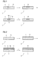
- FIG. 1 shows schematically the course of the method according to the invention.
- the component 1 in particular a component for steam or gas turbines 100 (FIG. 6), in particular a turbine blade 120, 130 (FIG. 4) or a combustion chamber element 155 (FIG. 5), preferably consists of a superalloy, which in the high-temperature applications consists of a nickel alloy. or cobalt-based superalloy, which then form the material for a substrate 4 of the component 1.
- the substrate 4 has a surface 10 in which build-up welding is to be carried out for component thickening (FIG. 2) or has a recess 7 (FIG. 1), for example a crack, which is to be welded, wherein in each case one welding filler material 13 is used ,
- the method for the recess 7 is explained by way of example.
- a well weldable filler metal 13 is introduced into the recess 7 and welded to the substrate 4, so that the recess 7 is filled and a welded area 16 without cracking or other errors arises according to a known method of the prior art.
- the filler metal 13 does not have the composition of the substrate 4.
- the used welding filler material 13 of the method according to the invention can be welded well, but does not have the same or clearly recognizable weaker mechanical properties at the operating temperatures and / or operating conditions of the component 1, 120, 130, 155 as the material of the substrate 4.
- the welding filler material 13 can be supplied in the form of a powder in the region 7 and melted or it is used in welding an electrode having the composition of the welding filler material 13. Further welding processes are conceivable.
- At least one metal (Me) is allowed to diffuse from an outer surface 11 of the welded region 16 into the welded region 16.
- Preferably, only one metallic element Me is allowed to diffuse into the welded region 16.
- This can be done by CVD, PVD methods ( Figure 1) or by coating methods in which the metal Me is fed as an ion, atom to the welded area.
- a large area application can be made (Fig. 2) by slip method, plasma spraying, etc. Other coating methods are conceivable.
- the slip method possibly even without masking
- the plasma spraying with masking can also be used.
- the one or at least one metal Me is in particular an alloying element of the substrate 4.
- the welded region 16 is here alitiert, ie aluminum diffuses into the welded region 16 into it.
- the proportion of the ⁇ '-phase that can arise in the welded region 16 is increased by the higher aluminum content, which significantly increases the mechanical properties, in particular the strength at high temperatures, due to the changed composition 13 '.
- the welded region 16 without the additional aluminum can form only a minor portion of the gamma prime phase and would result in lower mechanical strengths.
- this composition exhibits better weldability prior to alitization precisely because of the low ⁇ '-phase formation potential.
- titanium alone or titanium and aluminum may be allowed to diffuse in the welded area since titanium is also a gamma prime former.
- other ingredients may be allowed to diffuse into the welded area, such as chromium. It is also possible to diffuse aluminum and chromium into a nickel-based filler metal. This can be done sequentially or simultaneously.
- the modified welded region 16 ' preferably has the same composition as the substrate 4 (compositions see FIG. 3). Small differences between the substrate 4 and the region 16 'in the content of the diffused metal Me or metals Me are possible.
- a high proportion of the ⁇ ' phase can be formed in the desired manner.
- the proportion of the ⁇ 'phase in the diffusion-treated welded area 16' corresponds to ⁇ 10% of the proportion of the ⁇ 'phase of the substrate 4.
- solution heat treatment or aging treatment be performed according to the prior art.
- the substrate 4 used is preferably Rene 80, IN 738 LC or IN 939.
- the used welding filler material 13 then usually has a reduced aluminum content compared to.
- the material IN 625 (a Ni-Cr alloy without ⁇ '-former) can be used as welding filler material, to which material then ⁇ '-formers are added.
- IN 625 has the following composition (supplied by Haynes High Temperature Alloys): (in wt%) cobalt max. 1%, iron max. 5%, chromium 21%, molybdenum 9%, hafnium + tantalum (3.7%), manganese 0.5%, silicon max. 0.5%, aluminum max. 0.4%, titanium max. 0.4%, carbon max. 0.1%, balance nickel.
- FIG. 4 shows a perspective view of a moving blade 120 or guide blade 130 of a turbomachine that extends along a longitudinal axis 121.
- the turbomachine may be a gas turbine of an aircraft or a power plant for power generation, a steam turbine or a compressor.
- the blade 120, 130 has along the longitudinal axis 121 consecutively a fastening region 400, a blade platform 403 adjoining thereto and an airfoil 406. As a guide blade 130, the blade 130 may have at its blade tip 415 another platform (not shown).
- a blade root 183 is formed, which serves for attachment of the blades 120, 130 to a shaft or a disc (not shown).
- the blade root 183 is designed, for example, as a hammer head. Other designs as Christmas tree or Schwalbenschwanzfuß are possible.
- the blade 120, 130 has a leading edge 409 and a trailing edge 412 for a medium flowing past the airfoil 406.
- blades 120, 130 for example, solid metallic materials, in particular superalloys, are used in all regions 400, 403, 406 of the blade 120, 130.
- Such superalloys are for example from EP 1 204 776 B1 .
- EP 1 306 454 .
- the blade 120, 130 can be made by a casting process, also by directional solidification, by a forging process, by a milling process or combinations thereof.
- the blades 120, 130 may have coatings against corrosion or oxidation, e.g. M is at least one element of the group iron (Fe), cobalt (Co), nickel (Ni), X is an active element and stands for yttrium (Y) and / or silicon and / or at least one element of the rare ones Earth, or hafnium (Hf)).
- M is at least one element of the group iron (Fe), cobalt (Co), nickel (Ni)
- X is an active element and stands for yttrium (Y) and / or silicon and / or at least one element of the rare ones Earth, or hafnium (Hf)).
- Such alloys are known from the EP 0 486 489 B1 . EP 0 786 017 B1 . EP 0 412 397 B1 or EP 1 306 454 A1 which are to be part of this disclosure with regard to the chemical composition of the alloy.
- a thermal barrier coating consists for example of ZrO 2 , Y 2 O 3 -ZrO 2 , ie it is not, partially or completely stabilized by yttria and / or calcium oxide and / or magnesium oxide.
- suitable coating methods such as, for example, electron beam evaporation (EB-PVD), stalk-shaped grains are produced in the thermal barrier coating or, for example, atmospheric plasma spraying (APS) produces porous, micro- and macrocracked grains in the thermal barrier coating.
- Refurbishment means that components 120, 130 may have to be freed of protective layers after use (eg by sandblasting). After that a removal of the corrosion and / or oxidation layers or products takes place. Optionally, even cracks in the component 120, 130 are repaired by the method according to the invention. This is followed by a re-coating of the component 120, 130 and a renewed use of the component 120, 130.
- the blade 120, 130 may be hollow or solid. If the blade 120, 130 is to be cooled, it is hollow and may still film cooling holes 418 (indicated by dashed lines) on.
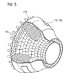
- FIG. 5 shows a combustion chamber 110 of a gas turbine 100 (FIG. 6).
- the combustion chamber 110 is designed, for example, as a so-called annular combustion chamber, in which a plurality of burners 107 arranged around a rotation axis 102 in the circumferential direction open into a common combustion chamber space 154, which generate flames 156.
- the combustion chamber 110 is configured in its entirety as an annular structure, which is positioned around the axis of rotation 102 around.
- the combustion chamber 110 is designed for a comparatively high temperature of the working medium M of about 1000 ° C to 1600 ° C.
- the combustion chamber wall 153 is provided on its side facing the working medium M side with an inner lining formed from heat shield elements 155.
- Each heat shield element 155 made of an alloy is equipped on the working medium side with a particularly heat-resistant protective layer (MCrAlX layer and / or ceramic coating) or is made of high-temperature-resistant material (solid ceramic blocks).
- M is at least an element of the group iron (Fe), cobalt (Co), nickel (Ni), X is an active element and stands for yttrium (Y) and / or silicon and / or at least one element of the rare earths, or hafnium (Hf) ,
- MCrAlX means: M is at least an element of the group iron (Fe), cobalt (Co), nickel (Ni), X is an active element and stands for yttrium (Y) and / or silicon and / or at least one element of the rare earths, or hafnium (Hf) ,
- Such alloys are known from the EP 0 486 489 B1 .
- EP 0 412 397 B1 or EP 1 306 454 A1 which are to be part of this disclosure with regard to the chemical composition of the alloy.
- a ceramic thermal barrier coating consists for example of ZrO 2 Y 2 O 3 -ZrO 2 , ie it is not, partially or completely stabilized by yttria and / or calcium oxide and / or magnesium oxide.
- suitable coating processes such as electron beam evaporation (EB-PVD), stalk-shaped grains are produced in the thermal barrier coating.
- Refurbishment means that heat shield elements 155 may need to be deprotected (e.g., by sandblasting) after use. This is followed by removal of the corrosion and / or oxidation layers or products. Optionally, cracks in the heat shield element 155 are also repaired by the method according to the invention. This is followed by a recoating of the heat shield elements 155 and a renewed use of the heat shield elements 155.
- the heat shield elements 155 are then, for example, hollow and possibly still have film cooling holes (not shown) which open into the combustion chamber space 154.
- FIG. 6 shows by way of example a gas turbine 100 in a longitudinal partial section.
- the gas turbine 100 has inside a rotatably mounted about a rotation axis 102 rotor 103 with a shaft 101, which is also referred to as a turbine runner.
- a compressor 105 for example, a toroidal combustion chamber 110, in particular annular combustion chamber, with a plurality of coaxially arranged burners 107, a turbine 108 and the exhaust housing 109th
- the annular combustion chamber 110 communicates with an annular annular hot gas channel 111, for example.
- Each turbine stage 112 is formed, for example, from two blade rings.
- a series 125 formed of rotor blades 120 follows.
- the guide vanes 130 are fastened to an inner housing 138 of a stator 143, whereas the moving blades 120 of a row 125 are attached to the rotor 103 by means of a turbine disk 133, for example. Coupled to the rotor 103 is a generator or work machine (not shown).
- air 105 is sucked in and compressed by the compressor 105 through the intake housing 104.
- the compressed air provided at the turbine-side end of the compressor 105 is supplied to the burners 107 where it is mixed with a fuel.
- the mixture is then burned to form the working fluid 113 in the combustion chamber 110.
- the working medium 113 flows along the hot gas channel 111 past the guide vanes 130 and the rotor blades 120.
- the working medium 113 expands in a pulse-transmitting manner, so that the rotor blades 120 drive the rotor 103 and drive the machine coupled to it.
- the components exposed to the hot working medium 113 are subject to thermal loads during operation of the gas turbine 100.
- the guide vanes 130 and rotor blades 120 of the first turbine stage 112, viewed in the flow direction of the working medium 113, are subjected to the greatest thermal stress in addition to the heat shield elements lining the annular combustion chamber 110. To withstand the prevailing temperatures, they can be cooled by means of a coolant.
- substrates of the components can have a directional structure, ie they are monocrystalline (SX structure) or have only longitudinal grains (DS structure).
- SX structure monocrystalline
- DS structure only longitudinal grains
- Such superalloys are for example from EP 1 204 776 B1 .
- EP 1 306 454 .
- the vane 130 has a guide vane foot (not shown here) facing the inner housing 138 of the turbine 108 and a vane head opposite the vane foot.
- the vane head faces the rotor 103 and fixed to a mounting ring 140 of the stator 143.
Landscapes
- Engineering & Computer Science (AREA)
- Chemical & Material Sciences (AREA)
- Mechanical Engineering (AREA)
- Organic Chemistry (AREA)
- Materials Engineering (AREA)
- Metallurgy (AREA)
- Physics & Mathematics (AREA)
- Chemical Kinetics & Catalysis (AREA)
- Plasma & Fusion (AREA)
- Thermal Sciences (AREA)
- Crystallography & Structural Chemistry (AREA)
- General Engineering & Computer Science (AREA)
- Turbine Rotor Nozzle Sealing (AREA)
Priority Applications (2)
| Application Number | Priority Date | Filing Date | Title |
|---|---|---|---|
| EP06000850A EP1808572A1 (fr) | 2006-01-16 | 2006-01-16 | Procédé de soudage suivi d'un traitement de diffusion |
| PCT/EP2007/050054 WO2007082787A1 (fr) | 2006-01-16 | 2007-01-03 | Procede de soudage suivi par un traitement de diffusion |
Applications Claiming Priority (1)
| Application Number | Priority Date | Filing Date | Title |
|---|---|---|---|
| EP06000850A EP1808572A1 (fr) | 2006-01-16 | 2006-01-16 | Procédé de soudage suivi d'un traitement de diffusion |
Publications (1)
| Publication Number | Publication Date |
|---|---|
| EP1808572A1 true EP1808572A1 (fr) | 2007-07-18 |
Family
ID=36587156
Family Applications (1)
| Application Number | Title | Priority Date | Filing Date |
|---|---|---|---|
| EP06000850A Withdrawn EP1808572A1 (fr) | 2006-01-16 | 2006-01-16 | Procédé de soudage suivi d'un traitement de diffusion |
Country Status (2)
| Country | Link |
|---|---|
| EP (1) | EP1808572A1 (fr) |
| WO (1) | WO2007082787A1 (fr) |
Cited By (2)
| Publication number | Priority date | Publication date | Assignee | Title |
|---|---|---|---|---|
| WO2011042006A1 (fr) | 2009-10-10 | 2011-04-14 | Mtu Aero Engines Gmbh | Procédé de soudage par fusion d'une pièce monocristalline et d'une pièce polycristalline, et rotor |
| EP2322681A1 (fr) * | 2009-11-11 | 2011-05-18 | Siemens Aktiengesellschaft | Procédé destiné à éviter la recristallisation par traitement à l'alite |
Citations (5)
| Publication number | Priority date | Publication date | Assignee | Title |
|---|---|---|---|---|
| EP0491189A1 (fr) * | 1990-12-18 | 1992-06-24 | General Electric Company | Fabrication d'articles moulés par composition de superalliages à température de fusion élevée |
| RU2121419C1 (ru) * | 1997-05-23 | 1998-11-10 | Открытое акционерное общество Институт технологии и организации производства | Способ восстановления пера лопатки турбомашины |
| US5951792A (en) * | 1997-09-22 | 1999-09-14 | Asea Brown Boveri Ag | Method for welding age-hardenable nickel-base alloys |
| US20040050909A1 (en) * | 2002-07-03 | 2004-03-18 | Federico Renteria | Diffusion bond mixture for healing single crystal alloys |
| US20050139581A1 (en) * | 2003-12-24 | 2005-06-30 | Yiping Hu | High-strength superalloy joining method for repairing turbine blades |
-
2006
- 2006-01-16 EP EP06000850A patent/EP1808572A1/fr not_active Withdrawn
-
2007
- 2007-01-03 WO PCT/EP2007/050054 patent/WO2007082787A1/fr not_active Ceased
Patent Citations (5)
| Publication number | Priority date | Publication date | Assignee | Title |
|---|---|---|---|---|
| EP0491189A1 (fr) * | 1990-12-18 | 1992-06-24 | General Electric Company | Fabrication d'articles moulés par composition de superalliages à température de fusion élevée |
| RU2121419C1 (ru) * | 1997-05-23 | 1998-11-10 | Открытое акционерное общество Институт технологии и организации производства | Способ восстановления пера лопатки турбомашины |
| US5951792A (en) * | 1997-09-22 | 1999-09-14 | Asea Brown Boveri Ag | Method for welding age-hardenable nickel-base alloys |
| US20040050909A1 (en) * | 2002-07-03 | 2004-03-18 | Federico Renteria | Diffusion bond mixture for healing single crystal alloys |
| US20050139581A1 (en) * | 2003-12-24 | 2005-06-30 | Yiping Hu | High-strength superalloy joining method for repairing turbine blades |
Cited By (5)
| Publication number | Priority date | Publication date | Assignee | Title |
|---|---|---|---|---|
| WO2011042006A1 (fr) | 2009-10-10 | 2011-04-14 | Mtu Aero Engines Gmbh | Procédé de soudage par fusion d'une pièce monocristalline et d'une pièce polycristalline, et rotor |
| DE102009048957A1 (de) | 2009-10-10 | 2011-04-14 | Mtu Aero Engines Gmbh | Verfahren zum Schmelzschweißen eines einkristallinen Werkstücks mit einem polykristallinen Werkstück und Rotor |
| DE102009048957B4 (de) * | 2009-10-10 | 2011-09-01 | Mtu Aero Engines Gmbh | Verfahren zum Schmelzschweißen eines einkristallinen Werkstücks mit einem polykristallinen Werkstück und Rotor |
| DE102009048957C5 (de) * | 2009-10-10 | 2014-01-09 | Mtu Aero Engines Gmbh | Verfahren zum Schmelzschweißen eines einkristallinen Werkstücks mit einem polykristallinen Werkstück und Rotor |
| EP2322681A1 (fr) * | 2009-11-11 | 2011-05-18 | Siemens Aktiengesellschaft | Procédé destiné à éviter la recristallisation par traitement à l'alite |
Also Published As
| Publication number | Publication date |
|---|---|
| WO2007082787A1 (fr) | 2007-07-26 |
Similar Documents
| Publication | Publication Date | Title |
|---|---|---|
| EP2458025B1 (fr) | Alliage, couche de protection et composant | |
| EP2612949B1 (fr) | Alliage, couche de protection et composant | |
| EP1967312A1 (fr) | Procédé de réparation par soudure d'un composant sous vide et sous une pression partielle d'oxygène choisie | |
| EP1716965A1 (fr) | Brasure comprenant de la poudre d'apport métallique sous forme élémentaire | |
| EP2476507B1 (fr) | Alliage de brasage et procédé destiné à la réparation d'un composant | |
| EP2474413A1 (fr) | Alliage, couche de protection et composant | |
| EP1595633B2 (fr) | Utilisation d'un mélange gazeux en soudage. | |
| EP1798299B1 (fr) | Alliage, couche de protection et élément de construction | |
| WO2007048696A1 (fr) | Procede de nettoyage aux ions fluor de composants oxydes ou attaques par la corrosion | |
| EP1790743A1 (fr) | Alliage, couche de protection et composant | |
| EP2637820A1 (fr) | Alliages à base de cobalt et contenant de germanium, et procédé de brasage | |
| EP2661370B1 (fr) | Alliage, couche protectrice et pièce | |
| EP2611949B1 (fr) | Alliage a base nickel, couche de protection et élément de construction | |
| EP1681374B1 (fr) | Système de revêtement comprenant une couche barrière et procédé de fabrication | |
| EP1970156A1 (fr) | Alliage de brasage et procédé destiné à la réparation d'un composant | |
| EP1808572A1 (fr) | Procédé de soudage suivi d'un traitement de diffusion | |
| EP1790746B1 (fr) | Alliage, couche de protection et composant | |
| EP2086715A1 (fr) | Poudre de brasage composite constituée d'une âme et d'une enveloppe métallique, pour le brasage d'éléments de turbine | |
| EP1930115A1 (fr) | Fil, son utilisation et procédé de soudage | |
| EP1806419B1 (fr) | Alliage, couche protectrice pour proteger un élément structurel contre la corrosion et l'oxydation aux temperatures hautes, et élément structurel | |
| WO2009018839A1 (fr) | Alliage de brasage et procédé de réparation d'un composant | |
| EP2345748A1 (fr) | Alliage, couche de protection et composant | |
| EP1867749A1 (fr) | Procédé de revêtement d'un matériau à une pièce | |
| EP1932935A1 (fr) | Procédé de fabrication d'une aube de turbine avec une couche d'oxide, une aube de turbine et son utilisation, et procédé de fonctionnement d'une turbine | |
| EP1818419A1 (fr) | Alliage, couche de protection et composant |
Legal Events
| Date | Code | Title | Description |
|---|---|---|---|
| PUAI | Public reference made under article 153(3) epc to a published international application that has entered the european phase |
Free format text: ORIGINAL CODE: 0009012 |
|
| AK | Designated contracting states |
Kind code of ref document: A1 Designated state(s): AT BE BG CH CY CZ DE DK EE ES FI FR GB GR HU IE IS IT LI LT LU LV MC NL PL PT RO SE SI SK TR |
|
| AX | Request for extension of the european patent |
Extension state: AL BA HR MK YU |
|
| AKX | Designation fees paid | ||
| STAA | Information on the status of an ep patent application or granted ep patent |
Free format text: STATUS: THE APPLICATION IS DEEMED TO BE WITHDRAWN |
|
| 18D | Application deemed to be withdrawn |
Effective date: 20080119 |
|
| REG | Reference to a national code |
Ref country code: DE Ref legal event code: 8566 |