EP1808666B1 - Testgerät zum Testen der Funktionsfähigkeit eines Warnsystems für sich nähernde Lenkwaffen - Google Patents
Testgerät zum Testen der Funktionsfähigkeit eines Warnsystems für sich nähernde Lenkwaffen Download PDFInfo
- Publication number
- EP1808666B1 EP1808666B1 EP06075083.3A EP06075083A EP1808666B1 EP 1808666 B1 EP1808666 B1 EP 1808666B1 EP 06075083 A EP06075083 A EP 06075083A EP 1808666 B1 EP1808666 B1 EP 1808666B1
- Authority
- EP
- European Patent Office
- Prior art keywords
- test apparatus
- led
- uvc
- sensor
- controller
- Prior art date
- Legal status (The legal status is an assumption and is not a legal conclusion. Google has not performed a legal analysis and makes no representation as to the accuracy of the status listed.)
- Expired - Lifetime
Links
Images


Classifications
-
- F—MECHANICAL ENGINEERING; LIGHTING; HEATING; WEAPONS; BLASTING
- F41—WEAPONS
- F41G—WEAPON SIGHTS; AIMING
- F41G7/00—Direction control systems for self-propelled missiles
- F41G7/001—Devices or systems for testing or checking
- F41G7/002—Devices or systems for testing or checking target simulators
-
- A—HUMAN NECESSITIES
- A61—MEDICAL OR VETERINARY SCIENCE; HYGIENE
- A61F—FILTERS IMPLANTABLE INTO BLOOD VESSELS; PROSTHESES; DEVICES PROVIDING PATENCY TO, OR PREVENTING COLLAPSING OF, TUBULAR STRUCTURES OF THE BODY, e.g. STENTS; ORTHOPAEDIC, NURSING OR CONTRACEPTIVE DEVICES; FOMENTATION; TREATMENT OR PROTECTION OF EYES OR EARS; BANDAGES, DRESSINGS OR ABSORBENT PADS; FIRST-AID KITS
- A61F7/00—Heating or cooling appliances for medical or therapeutic treatment of the human body
- A61F7/007—Heating or cooling appliances for medical or therapeutic treatment of the human body characterised by electric heating
-
- A—HUMAN NECESSITIES
- A61—MEDICAL OR VETERINARY SCIENCE; HYGIENE
- A61H—PHYSICAL THERAPY APPARATUS, e.g. DEVICES FOR LOCATING OR STIMULATING REFLEX POINTS IN THE BODY; ARTIFICIAL RESPIRATION; MASSAGE; BATHING DEVICES FOR SPECIAL THERAPEUTIC OR HYGIENIC PURPOSES OR SPECIFIC PARTS OF THE BODY
- A61H23/00—Percussion or vibration massage, e.g. using supersonic vibration; Suction-vibration massage; Massage with moving diaphragms
- A61H23/02—Percussion or vibration massage, e.g. using supersonic vibration; Suction-vibration massage; Massage with moving diaphragms with electric or magnetic drive
-
- A—HUMAN NECESSITIES
- A61—MEDICAL OR VETERINARY SCIENCE; HYGIENE
- A61F—FILTERS IMPLANTABLE INTO BLOOD VESSELS; PROSTHESES; DEVICES PROVIDING PATENCY TO, OR PREVENTING COLLAPSING OF, TUBULAR STRUCTURES OF THE BODY, e.g. STENTS; ORTHOPAEDIC, NURSING OR CONTRACEPTIVE DEVICES; FOMENTATION; TREATMENT OR PROTECTION OF EYES OR EARS; BANDAGES, DRESSINGS OR ABSORBENT PADS; FIRST-AID KITS
- A61F7/00—Heating or cooling appliances for medical or therapeutic treatment of the human body
- A61F2007/0001—Body part
- A61F2007/0039—Leg or parts thereof
- A61F2007/0045—Foot
-
- A—HUMAN NECESSITIES
- A61—MEDICAL OR VETERINARY SCIENCE; HYGIENE
- A61F—FILTERS IMPLANTABLE INTO BLOOD VESSELS; PROSTHESES; DEVICES PROVIDING PATENCY TO, OR PREVENTING COLLAPSING OF, TUBULAR STRUCTURES OF THE BODY, e.g. STENTS; ORTHOPAEDIC, NURSING OR CONTRACEPTIVE DEVICES; FOMENTATION; TREATMENT OR PROTECTION OF EYES OR EARS; BANDAGES, DRESSINGS OR ABSORBENT PADS; FIRST-AID KITS
- A61F7/00—Heating or cooling appliances for medical or therapeutic treatment of the human body
- A61F2007/0088—Radiating heat
-
- A—HUMAN NECESSITIES
- A61—MEDICAL OR VETERINARY SCIENCE; HYGIENE
- A61H—PHYSICAL THERAPY APPARATUS, e.g. DEVICES FOR LOCATING OR STIMULATING REFLEX POINTS IN THE BODY; ARTIFICIAL RESPIRATION; MASSAGE; BATHING DEVICES FOR SPECIAL THERAPEUTIC OR HYGIENIC PURPOSES OR SPECIFIC PARTS OF THE BODY
- A61H23/00—Percussion or vibration massage, e.g. using supersonic vibration; Suction-vibration massage; Massage with moving diaphragms
- A61H23/02—Percussion or vibration massage, e.g. using supersonic vibration; Suction-vibration massage; Massage with moving diaphragms with electric or magnetic drive
- A61H23/0218—Percussion or vibration massage, e.g. using supersonic vibration; Suction-vibration massage; Massage with moving diaphragms with electric or magnetic drive with alternating magnetic fields producing a translating or oscillating movement
- A61H2023/0227—Percussion or vibration massage, e.g. using supersonic vibration; Suction-vibration massage; Massage with moving diaphragms with electric or magnetic drive with alternating magnetic fields producing a translating or oscillating movement with magnetostrictive elements
Definitions
- the present invention relates to a test apparatus for testing the operability of a warning system for approaching guided weapons according to claim 1. It is thus in the field of
- Self-protection systems designed to protect aircraft, vehicles, ships, etc. and its occupants from attack. These systems include sensors that respond to emissions emanating from an approaching weapon system, such as a missile or guided missile. If such a system has detected an approaching missile, a defense system can be activated that will cause that missile to not be dangerous to the target. To be on the safe side, these sensors of the self-protection system should be tested for their function before each use.
- the present invention relates to test equipment that simulates a hazard simulation and confirms the functionality of the self-protection system to the crew or maintenance personnel.
- the patent application US 2005/0150371 A1 describes a countermeasure system for the defense of aircraft against rocket attacks.
- the system includes a detector which is located on the ground, but may alternatively be mounted on the aircraft. If the system detects an approaching rocket, the aircraft subsystem will turn one Cloud strewn with fluorescent nanocrystals. The resulting cloud of nanocrystals is then activated by irradiation, eg by laser, in order to generate a hot spot for the missile and to deflect it away from the aircraft.
- a "Missile Approach Warning Sensor” therefore permanently searches the environment for IR and / or UV suspicious sources. If the MAWS discovers a suspicious source, a special calculation algorithm analyzes the intensity profile of the source. An approaching missile reveals itself through a specific "missile profile", which increases in intensity. A MAWS must quickly grasp this threat so that necessary countermeasures can be taken in good time. The direction from which a danger approaches is shown on a display in the cockpit.
- the current stimulus technology based on hot sources (with IR, VIS and UV components), can only meet the requirements for a handheld device due to high energy requirements and the risk of overheating.
- the halogen and gas discharge lamps used in the prior art are not well suited for handheld devices. These disadvantages could be circumvented with a convenient UV source, which would also be suitable for a hand-held MAWS tester.
- US 5,693,951 describes a device with which an approaching guided missile can be simulated.
- the device uses a halogen lamp that emits light that has different proportions of UV and IR depending on the current flowing.
- the signature of a guided missile from start (high UV intensity) to burning (low UV, high, decreasing IR proportion) can be reproduced.
- the device is placed on the ground and when approached generates a light signal that can be detected by a MAWS in an approaching aircraft. Because of the relatively large distance between the device and the aircraft as well as because of the light source used large amounts of energy are needed that allow at most a transport on a vehicle and either require power from the grid or powerful and therefore voluminous and heavy batteries.
- test device also called Missile Approach Warning Tester, abbreviated MAWST, according to claim 1.
- MAWST Missile Approach Warning Tester
- LED Light Emitting Diode
- UVC LED For the present invention, a commercial UVC LED was used, which emits light waves in the range of about 265nm wavelength. Since this wavelength is also included in the bandwidth for UV-MAW sensors (which primarily detect in the solar blind area), such UVC LEDs are ideal for this application.
- the relatively short life of the currently available UVD LEDs is not a serious drawback for the simulation since a UVC LED used for a test is only put into operation for a few seconds.
- MAWS test device In order for the MAWS test device (MAWST) to come as close as possible to the characteristics of the UV of a real guided missile, measurements on an integrated self-protection system in an aircraft were carried out and verified.
- the MAWST is programmed so that when activated a UV emission profile of an approaching guided missile is simulated by means of a UV source, according to the invention with a UVC LED.
- the intensity course is decisive, so that the sensor can really perceive the light source as a danger.
- the danger detected by the sensor and its direction are transmitted by the MAWS into the cockpit, where the pilot is alerted to the danger on a display, whereby immediate countermeasures are taken in the event of danger (for guided weapons usually flares, flares which are to act as a disturbing heat source).
- the internal self-test can not check all parts of the MAWS before departure, it needs an external test for the sensor. This is to once again prove the functionality of the sensor or to reduce sources of error on parts which are not to be electronically checked, such as soiled protective glass in front of a sensor.
- the MAWST has to simulate a guided missile with regard to the UV-radiation in such a way that the danger is really recognized as such by the sensor. Since most MAWS operate in the UV range, a test light needs a light source in this area. In order to stimulate the MAWS available on the market, one needs a source in the UVC range (for more details see below).
- the power supply of the MAWST which is to function as an autonomous device, is preferably a rechargeable battery or a non-rechargeable battery.
- a button can be provided with which by closing a circuit during the required period of time the profile can be started or stopped.
- the MAWST uses a programmable controller to compensate for nonlinearities or other influences.
- the target values of a UV emission profile of an approaching generic missile come from calculated profiles or from real records that can be loaded into the MAWST.
- the values describe an intensity profile of an approaching missile.
- the waveforms are roughly based on a quadratic function, since the light output also behaves quadratically to the distance.
- the controlled system (outside and / or inside the microcontroller) consists of an amplifier element and the UV LED.
- the amplifier is necessary because the operating point of the UV-LED is only above the supply voltage of the microcontroller.
- the voltage, current and temperature of the UV LED are fed back to the controller as actual values and can be used for control purposes.
- the version of MAWST described above is a low cost version. E additional functions can be integrated into the device, which can also be taken into account in a series production.
- the MAWST is calibrated by an external device.
- UVC LEDs were UVTOP ® LEDs Sensor Electronic Technology, Inc. 1195 Atlas Road Columbia, SC 29209, USA used.
- the product UVTOP-265 has a peak wavelength of 263 +/- 7nm. This was confirmed by a measurement by the applicant. Also the Spectrum Half Width of 12-20nm was kept. However, other such products which meet the requirements may also be used.
- the removal of the MAWST from the MAW sensor at the ISSYS is also important because the light output decreases quadratically with increasing distance.
- a distance meter is installed which, when the test device is used in the switched-on state, measures the distance between the UVC LED and the sensor of the MAWS.
- the optical output line is controlled by the programmable controller so that the performance of the UVC LED is within the desired specification. The user no longer has to worry about the distance to the sensor.
- a measuring sensor is arranged in front of the UVC-LED, which measures the intensity of the emitted radiation and controls it by the controller, wherein the arrangement with the measuring sensor contains a semi-transparent mirror, which forms part of the optical Signals for the measurement to the measuring sensor branches off.
- a further embodiment of the test device additionally has an optical fiber cable, which is arranged in front of the UVC LED for forwarding the emitted optical signal.
- the optical signal can thereby be fed close to the sensor of the MAWS for the purpose of a shielded simulation.
- the heart of the MAWST is a programmable controller. He controls and monitors the modules on the circuit board.
- the light output is controlled by the current.
- the circuit is based on the principle of a regulated current source with an operational amplifier.
- the current is fed back via a shunt to the inverted input at the OPAMP.
- the setpoint is routed to the positive input.
- the output voltage then continues to rise until the difference between the positive and the inverted input is zero.
- a variant of a housing consists of glass fiber reinforced plastic (GRP), which has a simple solution for changing the battery.
- GRP glass fiber reinforced plastic
- the actuation of the modules used and above all the UV LED is carried out via the programmable controller. This requires a suitable firmware in the controller and profile data for the correct control and monitoring.
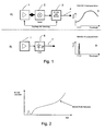
- Fig. 1 shows the difference of a conventional test device with a lamp to the inventive LED device. Since most Missile sensors work in the infrared and ultraviolet range, various halogen solutions and various gas discharge lamps for test equipment have been used so far.
- An exemplary arrangement is under A) in Fig. 1 shown.
- Figure 1 illustrates the electronics, including the power supply and controller controlling the lamp 2. Expensive optical filters, shutters 3 were necessary whose output power must be controlled in the required spectral range in order to achieve the desired radiation intensity 4. The nonlinearities as well as fast intensity changes with control devices had to be considered by the electronics. These solutions are expensive, require a lot of energy, are impractical to use and often unreliable.
- B) in Fig. 1 we show the inventive arrangement. It also includes electronics 1, which alone has to regulate the LED 6, so that the desired radiation intensity 7 is achieved. Furthermore, the difference between the output spectra 5 and 8 can be seen schematically from the illustration.
- Fig. 2 shows the intensity curve of a missile approaching the MAWS.
- the intensity according to this curve must be controlled by the electronics of the be simulated MAWST according to the invention, wherein a calculated curve is used.
- Fig. 3 represents a measuring arrangement with an inventive MAWST 30.
- the UVC LED 32 is activated and radiates with a predetermined intensity pattern on the sensor 33 of the MAWS.
- the signal is processed by the electronics 34 (here EWC) and forwarded in the test case only to a display 35 in the cockpit, where the functionality of the MAWS is confirmed.
- Fig. 4 shows a block diagram, which contains the essential elements of a test device 40 according to the invention.
- the power source 41 ensures that the MAWST can function as an autonomous device.
- the power source 41 consists of an accumulator or a battery and provides the microcontroller 44 the necessary energy for the UV-LED 46 and for the control when the power-on 42 is made by the user with the button 43.
- the light output is controlled by the current using an operational amplifier 45 (OPAMP), which can be used as a regulator.
- OPAMP operational amplifier
- the current is fed back via a shunt 47 to the inverted input on the OPAMP.
- the setpoint is routed to the positive input.
- Fig. 5 shows a usable control loop of a microcontroller 50.
- the setpoints (S) are composed of a generic profile.
- For the functional pattern is usually not a profile of an existing missile used, but a calculated profile.
- the values describe an intensity profile of an approaching missile.
- the waveform is roughly based on a quadratic function, since the light output also behaves quadratically to the distance.
- the controlled system 51 (outside the microcontroller) consists of an amplifier element and the UV LED. The amplifier is necessary because the UV LED starts to conduct only above the supply voltage of the microcontroller. Activation via a "normal" output of the controller is therefore not possible. Voltage, current and temperature of the UV-LED are fed back to the controller as actual values.
- Fig. 6 shows a plot of the intensity profile of UVTOP-265 UVC LED used by Sensor Electronic Technology, Inc., Columbia, SC 29209, USA.
- Fig. 7 shows a built in a housing 70 MAWST with the UVC LED 71, the button 72 and a warning light 73rd
- Fig. 8 shows a further embodiment of the inventive MAWST with a regulated light output.
- the arrangement corresponds to that of Fig. 4
- the intensity of the UV beam is measured by a measuring sensor assembly 80 and controlled by additional electronic components 82, 83.
- a transmissive mirror 81 as optics, a small part of the UV light, which is intended for the MAWS sensor, is deflected onto the measuring sensor, which sends corresponding signals to the component 83.
- This takes into account changes in the UVC LED that may be caused by external influences or aging.
- This embodiment is not limited only to the use of a UVC LED but can also be applied to MAWSTs that operate in the IR range and / or use lamps or other radiation sources.
- Fig. 9 shows an embodiment with an output compensation by means of an automatic distance measurement.
- the incoming power at the sensor during a missile approach simulation is in the relationship: P E ⁇ P S / l 2 .
- the distance has a great influence on the input power and is therefore a critical size.
- the Missile Approach Simulator incorporates a distance meter that measures the distance between the simulator and the MAW sensor. Depending on the distance, the optical output power is adjusted on the simulator. This ensures that the optical power at the MAW sensor is always within the desired specification. The user no longer has to worry about the distance to the sensor.
- This embodiment is not limited only to the use of a UVC LED but can also be applied to MAWSTs that operate in the IR range and / or use lamps or other radiation sources.
- P S transmission power
- P E received power
- I distance transmitter - receiver
- Fig. 10 shows a further embodiment of a MAWST, in which the optical signal of a Missile Approach Simulator is fed very close to the Missile Approach Warning Sensor.
- This minimum distance specification enables the execution of shielded simulations. Since the optics of a MAW sensor are fixed to a fixed distance, the optics must be outsmarted from a short distance when feeding the optical signal. For this purpose, the use of optical fiber cable with an optical transmission of 160-10,000 nm is proposed. Due to the numerical aperture and the fiber diameter, the optical power can be adjusted and the exit angle calculated. The MAW sensor "sees" the optical signal at a small fiber diameter despite a small distance sharp.
- the lower part of the drawing shows a detail of the part, which is in the dotted circle of the upper overview drawing.
- This embodiment is not limited to the use of a UVC LED, but may also be applied to MAWSTs that operate in the IR range and / or use lamps or other radiation sources.
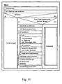
- the Fig. 11 to 13 represent structograms, which served as a basis for programming the controller, so that the control of the modules used and especially the UV LED works smoothly.
Landscapes
- Health & Medical Sciences (AREA)
- Engineering & Computer Science (AREA)
- General Health & Medical Sciences (AREA)
- Veterinary Medicine (AREA)
- Public Health (AREA)
- Life Sciences & Earth Sciences (AREA)
- Animal Behavior & Ethology (AREA)
- Chemical & Material Sciences (AREA)
- Biomedical Technology (AREA)
- Physical Education & Sports Medicine (AREA)
- Pain & Pain Management (AREA)
- Epidemiology (AREA)
- Combustion & Propulsion (AREA)
- General Engineering & Computer Science (AREA)
- Rehabilitation Therapy (AREA)
- Heart & Thoracic Surgery (AREA)
- Vascular Medicine (AREA)
- Optical Radar Systems And Details Thereof (AREA)
- Photometry And Measurement Of Optical Pulse Characteristics (AREA)
- Length Measuring Devices By Optical Means (AREA)
- Aiming, Guidance, Guns With A Light Source, Armor, Camouflage, And Targets (AREA)
Description
- Die vorliegende Erfindung bezieht sich auf ein Testgerät zum Testen der Funktionsfähigkeit eines Warnsystems für sich nähernde Lenkwaffen gemäss des Anspruchs 1. Sie liegt damit auf dem Gebiet der
- Selbstschutzsysteme, welche Flugzeuge, Fahrzeuge, Schiffe etc. und seine Insassen vor Angriffen schützen sollen. Diese Systeme umfassen Sensoren, die auf Emissionen reagieren, die von einem sich nähernden Waffensystem, wie einer Rakete oder Lenkwaffe, ausgehen. Hat ein solches System eine sich nähernde Lenkwaffe erkannt, kann ein Abwehrsystem aktiviert werden, das bewirkt, dass diese Rakete dem Ziel nicht gefährlich werden kann. Sicherheitshalber sollten diese Sensoren der Selbstschutzsysterne vor jedem Einsatz auf ihre Funktion getestet werden. Insbesondere bezieht sich die vorliegende Erfindung auf Testgeräte, die eine Gefahrensimulation simulieren und der Crew oder dem Wartungspersonal die Funktionsfähigkeit des Selbstschutzsystems bestätigen.
- Die Öffentlichkeit wurde erstmals durch einen Raketenangriff am 29. November 2002 auf ein israelisches Zivilflugzeug in Kenia auf die Gefahren aufmerksam gemacht, die von IR-Raketen ausgehen. Nicht nur militärische, sondern auch zivile Flugzeuge sind dieser Gefährdung ausgesetzt, die von terroristischen Aktivitäten ausgehen. Die Gefahr hat durch die Verbreitung von Schulter abgefeuerten Raketen (MANPADS = "man-portable air defense"), "Stinger", SAM 6, SAM 18 in den letzten Jahren zugenommen, da sie auf dem Schwarzmarkt zu tausenden erhältlich sind. Diese Raketen besitzen ein wärmegeleitetes Zielsystem (IR), das die Rakete auf die Wärme der Triebwerke richtet. Auf Grund der Reichweite dieser Raketen, besteht die Gefahr im Wesentlichen in der Start- und Landephase.
- Mit der Einführung von modernen Selbstschutz-Systemen auf Flugzeugen und Helikoptern kommen komplexe und empfindliche Umweltsensoren zum Einsatz, die für die Detektion von schnell nahenden Gefahren nötig sind. Die Patentanmeldung
US 2005/0150371 A1 beschreibt ein Gegenmassnahmen-System für die Verteidigung von Flugzeugen gegen Raketenangriffe. Das System umfasst einen Detektor, der sich am Boden befindet, alternativ jedoch auch am Flugzeug montiert sein kann. Weist das System eine sich nähernde Rakete nach, wird vom Flugzeug-Subsystem eine Wolke von fluoreszierenden Nanokristallen ausgestreut. Die entstehende Wolke von Nanokristallen wird danach durch Bestrahlung, z.B. durch Laser, aktiviert um für die Lenkwaffe einen Anlock-Hot Spot zu erzeugen und sie vom Flugzeug abzulenken. Die PatentanmeldungUS 2005/0029394 A1 beschreibt ein eingelassenes Luftverteidigungssystem (conformal air defense system) das an der Aussenseite eines Flugzeuges montiert werden kann. Das System enthält einen Sensor und auch ein Gegenmassnahmensystem. Weitere derartige System sind z.B. beschrieben inUS 2004/0174290 A1 undUS Patent 5 850 285 . Testsvorrichtungen für die Sensorsysteme werden in diesen Dokumenten nicht erwähnt. - Jedes Triebwerk einer fliegenden Lenkwaffe emittiert neben IR- auch UV-Strahlen. Ein "Missile Approach Warning Sensor" (MAWS) sucht daher die Umgebung permanent nach lR und/oder UV verdächtigen Quellen ab. Entdeckt der MAWS eine verdächtige Quelle, analysiert ein spezieller Rechenalgorithmus den Intensitätsverlauf der Quelle. Eine sich nähernde Missile verrät sich durch ein spezifisches "Missile-Profil", welches an Intensität zunimmt. Ein MAWS muss diese Bedrohung schnell erfassen, damit nötige Gegenmassnahmen rechtzeitig eingeleitet werden können. Die Richtung, aus welcher eine Gefahr herannaht, wird auf einem Display im Cockpit dargestellt.
- Die regelmässige Funktionsüberprüfung von solchen Sensoren ist daher ein überlebenswichtiger Vorgang und wird in der Regel vor jeder Mission durchgeführt.
- Die bisherige Stimulus-Technologie, basierend auf heissen Quellen (mit lR, VIS und UV Anteilen), kann aufgrund hohem Energiebedarf und Überhitzungsgefahr die Anforderungen für ein Handgerät nur beschränkt erfüllen. Die gemäss dem Stand der Technik verwendeten Halogen- und Gasentladungslampen sind für Handgeräte nicht gut geeignet. Diese Nachteile könnten mit einer zweckmässigen UV-Quelle umgangen werden, die auch für ein Hand-Held MAWS-Testgerät geeignet wäre.
-
US-5,693,951 beschreibt ein Gerät, mit dem eine annahende Lenkwaffe simuliert werden kann. Das Gerät verwendet eine Halogenlampe, die Licht ausgibt, das je nach fliessendem Strom andere Anteile von UV und IR aufweist. Damit kann die Signatur einer Lenkwaffe von Start (hohe UV-Intensität) bis Brennende (wenig UV; hoher, abnehmender IR Anteil) nachgebildet werden. Das Gerät wird am Boden aufgestellt und erzeugt bei Annäherung ein Lichtsignal, das von einem MAWS in einem heranfliegenden Luftfahrzeug detektiert werden kann. Wegen der relativ grossen Distanz zwischen Gerät und Luftfahrzeug wie auch wegen des verwendeten Leuchtmittels werden grosse Energiemengen benötigt, die allenfalls einen Transport auf einem Fahrzeug gestatten und entweder Stromversorgung aus dem Netz oder leistungsfähige und damit voluminöse und schwere Batterien erfordern. - Es besteht deshalb ein Bedürfnis nach einem Testgerät, das die UV-Strahlen einer Missile simulieren kann, das leicht, kompakt, mobil und einfach zu bedienen ist, aber auch unter härtesten Umweltbedingungen zuverlässig arbeitet. Ein derartiges Gerät soll diese Funktion als autonomes Hand-Held Gerät erfüllen.
- Es ist daher Aufgabe der vorliegenden Erfindung ein solches Gerät zur Verfügung zu stellen.
- Diese Aufgabe wird durch das Testgerät, auch genannt Missile Approach Warning Tester, abgekürzt MAWST, gemäss Anspruch 1 gelöst. Die weiteren Ansprüche geben bevorzugte Ausführungsformen an.
- Die Erfindung wird weiter anhand eines bevorzugten Ausführungsbeispiels unter Bezugnahme auf Figuren erläutert.
-
-
Fig. 1 zeigt den Unterschied eines konventionellen Testgerätes mit einer Lampe zum erfindungsgemässen Gerät. -
Fig. 2 zeigt die Intensitätskurve der Emission einer sich nähernden Lenkwaffe. -
Fig. 3 stellt eine Messanordnung mit einem erfindungsgemässen MAWST dar. -
Fig. 4 zeigt ein Blockschaltbild, das die wesentlichen Elemente eines erfindungsgemässen Testgeräts enthält. -
Fig. 5 zeigt einen einsetzbaren Regelkreis eines Microcontroller. -
Fig. 6 zeigt ein Diagramm des Intensitätsverlaufs der verwendeten UVC-LED -
Fig. 7 zeigt das in ein Gehäuse eingebautes MAWST. -
Fig. 8 zeigt eine weitere Ausgestaltung des erfindungsgemässen MAWST mit einer geregelten Lichtleistung. -
Fig. 9 zeigt eine Ausführungsform mit einer Ausgangsleistungskompensation mittels einer automatischen Distanzvermessung. -
Fig. 10 zeigt eine weitere Ausführungsform eines MAWST, bei welchem das optische Signal eines Missile Approach Simulator sehr nahe am Missile Approach Warning Sensor eingespeist wird. - Die
Fig. 11 bis 13 stellen Struktogramme dar, welche als Grundlage zur Programmierung des Microcontrollers dienten. - Die effizienteste Leuchtquelle ist nach heutigem Stand der Technik die Light Emitting Diode (LED), die in vielen Produkten als Beleuchtungskörper oder Kontrollampen zum Einsatz gelangen. Hohe Lichtausbeute, lange Lebensdauer und hohe Effizienz zeichnen diese Technologie aus und hat sich seit Jahrzehnten bewährt. Die Hersteller liefern viele verschiedene Grössen, Leistungsklassen und Wellenlängen.
- Es wurde gefunden, dass die LED-Technologie für ein MAWS-Testgerät (MAWST) geeignet ist und derartige LEDs bereits entwickelt wurden.
- Während leistungsstarke IR-LED im Handel erhältlich sind, gibt es jedoch bei den Wellenlängen im UV-Bereich nur wenige Produkte mit kürzerer Wellenlänge, die für MAWSTs geeignet sind. Sie haben generell folgende Nachteile: Tiefer Wirkungsgrad, Keine hohen Ausgangsleistungen, Lebensdauer im Vergleich zu Standard-LED relativ kurz, es gibt nur wenige Bezugsquellen für LEDs, die unter 300 nm emittieren. Vorgeschlagene Anwendungen für diese neuen UVC-LEDs liegen im Entkeimen von Flüssigkeiten (Trinkwasseraufbereitung oder Schwimmbeckenreinigung). Es werden aber auch militärischen Anwendungen geprüft, z.B. für die Datenübertragung. Man sendet die Daten mittels UV- Strahlung in den Himmel. Die Strahlen werden dann diffus reflektiert. Diese Übertragungsart dürfte nur für kurze Distanzen (innerhalb Gefechtsstand) geeignet sein. Ihre Anwendung in Missile Approach Simulatoren wurde bisher nicht vorgeschlagen.
- Für die vorliegende Erfindung wurde eine handelsübliche UVC-LED verwendet, welche Lichtwellen im Bereich um ca. 265nm Wellenlänge emittiert. Da diese Wellenlänge in der Bandbreite für UV-MAW-Sensoren (die primär im Solar-Blind Bereich detektieren) auch noch enthalten sind, sind solche UVC-LED für diese Anwendung ideal. Die relativ kurze Lebensdauer der gegenwärtig erhältlichen UVD-LEDs ist für die die Simulation kein gravierender Nachteil, da eine verwendete UVC-LED für einen Test nur während einigen Sekunden in Betrieb genommen wird.
- Damit das MAWS-Testgerät (MAWST) bezüglich des UV einer realen Lenkwaffe mit ihren Eigenschaften möglichst nahe kommt, wurden Messungen an einem integriertem Selbstschutzsystem in eine Flugzeug durchgeführt und verifiziert.
- Das MAWST wird so programmiert, dass bei Aktivierung ein UV-Emissionsprofil einer sich nähernden Lenkwaffe mittels einer UV-Quelle, erfindungsgemäss mit einer UVC-LED, simuliert wird. Bei diesem Profil ist der Intensitätsverlauf massgebend, damit der Sensor die Lichtquelle auch wirklich als Gefahr wahrnehmen kann. Die vom Sensor erkannte Gefahr und ihre Richtung werden vom MAWS ins Cockpit übermittelt, wo der Piloten auf einem Display auf die Gefahr aufmerksam gemacht wird, wobei im Gefahrenfall sofort Gegenmassnahmen getroffen werden (für Lenkwaffen meist Flares, Leuchtkugeln welche als störende Wärmequell wirken sollen). Da der interne Selbsttest aber vor einem Abflug nicht alle Teile des MAWS auf seine Funktion überprüfen kann, braucht es für den Sensor einen externen Test. Dieser soll die Funktionalität des Sensor noch einmal beweisen bzw. Fehlerquellen auf nicht elektronisch zu überprüfenden Teilen wie verschmutztes Schutzglas vor einem Sensor zu vermindern.
- Das MAWST muss also, eine Lenkwaffe bezüglich der UV-Abstahlung so simulieren, dass Gefahr vom Sensor auch wirklich als solche erkannt wird. Da die meisten MAWS im UV-Bereich arbeiten, benötigt man für ein Testgerät eine Lichtquelle in diesem Bereich. Um die auf dem Markt erhältlichen MAWS zu stimulieren, benötigt man eine Quelle im UVC Bereich (genauere Erläuterungen siehe weiter unten in der vorliegenden Beschreibung).
- Die Stromversorgung des MAWST, das als autonomes Gerät funktionieren soll, ist vorzugsweise ein Akkumulator oder eine nichtwiederaufladbare Batterie.
- Als Bedienelement kann eine Taste vorgesehen werden, mit welcher durch schliessen eines Stromkreises während der nötigen Zeitdauer das Profil gestartet bzw. beendet werden kann.
- Wie bei andern ähnlichen Geräten wird beim MAWST ein programmierbarer Controller eingesetzt um Unlinearitäten oder andere Einflüsse zu kompensieren.
- Die Sollwerte eines UV-Emissionsprofils einer sich annähernden generischen Lenkwaffe stammen aus gerechneten Profilen oder aus echten Aufzeichnungen, die in den MAWST geladen werden können. Die Werte beschreiben einen Intensitätsverlauf einer sich annähernde Lenkwaffe. Die Kurvenformen beruhen grob auf einer quadratischen Funktion, da sich die Lichtleistung auch quadratisch zur Distanz verhält. Die Regelstrecke (ausserhalb und/oder innerhalb des Mikrocontrollers) besteht aus einem Verstärkerglied und der UV-LED. Der Verstärker ist notwendig, da sich der Arbeitspunkt der UV-LED erst oberhalb der Speisespannung des Mikrocontrollers befindet. Spannung, Strom und Temperatur der UV-LED werden als Istwerte an den Controller zurückgeführt und könne für Regelzwecke verwendet werden.
- Die oben beschriebene Version des MAWST ist eine kostengünstige Version. E können noch zusätzliche Funktionen in das Gerät integriert werden, die bei einer Serieproduktion auch berücksichtigt werden können.
- Die Kalibration des MAWST erfolgt durch eine externen Einrichtung.
- Als UVC-LED wurden UVTOP® LEDs von Sensor Electronic Technology, Inc. 1195 Atlas Road Columbia, SC 29209, USA verwendet. Für das Produkt UVTOP-265 wird eine Spitzenwellenlänge mit 263 +/-7nm angegeben. Dies wurde durch eine Messung der Anmelderin bestätigt. Auch die Spectrum Half Width von 12-20nm wurde eingehalten. Andere derartige Produkte, welche die Voraussetzungen erfüllen, können jedoch auch verwendet werden.
- Für die Ausgangsleistungs-Messungen wurde ein Universal Lichtleistungs-Messgerät (Model 841-PE, UC-Sensor 818) von Newport (Newport Corporation, 8 East Forge Parkway Franklin, MA 02038 USA) verwendet, an welchem kalibrierte Power-Sensoren angehängt werden können. Das Datenblatt des Sensors und der Anzeigeeinheit ist auf der Website www.newport.com ersichtlich.
- Die Entfernung des MAWST vom MAW-Sensor am ISSYS ist im weiteren von Bedeutung, da die Lichtleistung bei zunehmender Distanz quadratisch abnimmt.
- In einer Ausführungsform des Testgeräts ist deshalb ein Distanzmesser eingebaut, der bei der Anwendung des Testgeräts in eingeschaltetem Zustand die Distanz zwischen der UVC-LED und dem Sensor des MAWS vermisst. Abhängig von der Distanz wird die optische Ausgangsleitung durch den programmierbaren Controller so gesteuert, dass die Leistung der UVC-LED innerhalb der gewünschten Spezifikation liegt. Der Anwender muss sich nicht mehr um die Distanz zum Sensor kümmern.
- In einer speziellen Ausführungsform des Testgeräts wird vor der UVC-LED ein Mess-Sensor angeordnet ist, der die Intensität der emittierten Strahlung misst und durch den Controller regelt, wobei die Anordnung mit dem Mess-Sensor einen halbtransparenten Spiegel enthält, der einen Teil des optischen Signals für die Messung zum Mess-Sensor abzweigt.
- Eine weitere Ausführungsform des Testgeräts weist zusätzlich ein Lichtleiterkabel auf, das vor der UVC-LED zur Weiterleitung des abgegebene optischen Signals angeordnet ist. Das optische Signal kann dadurch zwecks einer abgeschirmten Simulation, nahe am Sensor des MAWS eingespeist werden.
- Das Herzstück des MAWST ist ein programmierbarer Controller. Er steuert und überwacht die Baugruppen auf der Leiterplatte.
- Wie aus den obigen Ausführungen ersichtlich ist, wird die Lichtleistung über den Strom gesteuert. Die Schaltung beruht auf dem Prinzip einer geregelten Stromquelle mit einem Operationsverstärker. Der Strom wird über einen Shunt auf den invertierten Eingang am OPAMP zurückgeführt. Der Sollwert wird auf den positiven Eingang geführt. Die Ausgangsspannung fährt nun also so lange hoch, bis die Differenz zwischen positivem und invertiertem Eingang Null ergibt.
- Eine Variante eines Gehäuses besteht aus glasfaserverstärktem Kunststoff (GFK), das eine einfache Lösung für den Wechsel der Batterie aufweist.
- Die Ansteuerung der eingesetzten Baugruppen und vor allem der UV-LED erfolgt über den programmierbaren Controller. Dies bedingt eine geeignete Firmware im Controller und Profildaten für die korrekte Ansteuerung und Überwachung.
- Das Ausführungsbeispiel wird anhand der beiliegenden Zeichnungen näher erläutert.
-
Fig. 1 zeigt den Unterschied eines konventionellen Testgerätes mit einer Lampe zum erfindungsgemässen LED Gerät. Da die meisten Missile Sensoren im Infrarot- und Ultraviolett-Bereich arbeiten, kamen bisher diverse Leuchtkörperlösungen mit Halogen- und diverse Gasentladungs-Lampen für Testgeräte zum Einsatz. Ein beispielhafte Anordnung ist unter A) inFig. 1 dargestellt. 1 stellt die Elektronik, einschliesslich Speisung und Controller dar, der die Lampe 2 steuert. Es waren aufwändige optische Filter, Shutter 3 nötig, deren Ausgangsleistung im verlangten Spektralbereich geregelt werden müssen um die gewünschte Strahlungsintensität 4 zu erreichen. Auch die Unlinearitäten sowie schnelle Intensitätsveränderungen mit Steuervorrichtungen mussten von der Elektronik berücksichtigt werden. Diese Lösungen sind teuer, benötigen viel Energie, sind in der Anwendung unpraktisch und oft nicht zuverlässig. Unter B) inFig. 1 wir die erfindungsgemässe Anordnung dargestellt. Sie umfasst ebenfalls eine Elektronik 1, die allein die LED 6 zu regeln hat, damit die gewünschte Strahlungsintensität 7 erreicht wird. Weiter ist aus der Darstellung schematisch der Unterschied der Ausgangsspektren 5 bzw. 8 ersichtlich. -
Fig. 2 zeigt die Intensitätskurve einer sich dem MAWS nähernden Lenkwaffe. Die Intensität gemäss dieser Kurve muss durch die Elektronik des erfindungsgemässen MAWST simuliert werden, wobei ein berechnete Kurve verwendet wird. -
Fig. 3 stellt eine Messanordnung mit einem erfindungsgemässen MAWST 30 dar. Durch den Druck des Bedieners auf die Taste 31 wird die UVC-LED 32 aktiviert und strahlt mit einem vorgegeben Intensitätsmuster auf den Sensor 33 des MAWS. Das Signal wird durch die Elektronik 34 (hier EWC) verarbeitet und im Testfall lediglich an eine Anzeige 35 im Cockpit weitergeleitet, wo die Funktionsfähigkeit des MAWS bestätigt wird. -
Fig. 4 zeigt ein Blockschaltbild, das die wesentlichen Elemente eines erfindungsgemässen Testgeräts 40 enthält. Die Stromquelle 41 sorgt dafür, das das MAWST als autonomes Gerät funktionieren kann. Die Stromquelle 41 besteht aus einem Akkumulator oder einer Batterie und liefert dem Microcontroller 44 die nötige Energie für die UV-LED 46 und für die Steuerung, wenn die Einschaltvorrichtung 42 vom Anwender mit der Taste 43 getätigt wird. Die Lichtleistung wird über den Strom gesteuert, wobei ein Operationsverstärker 45 (OPAMP) eingesetzt wird, der als Regler benutzt werden kann. Der Strom wird über einen Shunt 47 auf den invertierten Eingang am OPAMP zurückgeführt. Der Sollwert wird auf den positiven Eingang geführt. -
Fig. 5 zeigt einen einsetzbaren Regelkreis eines Microcontroller 50. Die Sollwerte (S) setzen sich aus einem generischen Profil zusammen. Für das Funktionsmuster wird in der Regel nicht ein Profil einer bestehenden Lenkwaffe eingesetzt, sondern ein gerechnetes Profil. Die Werte beschreiben einen Intensitätsverlauf einer sich annähernden Lenkwaffe. Die Kurvenform beruht grob auf einer quadratischen Funktion, da sich die Lichtleistung auch quadratisch zur Distanz verhält. Die Regelstrecke 51 (ausserhalb des Mikrocontrollers) besteht aus einem Verstärkerglied und der UV-LED. Der Verstärker ist notwendig, da die UV-LED erst oberhalb der Speisespannung des Mikrocontrollers anfängt zu leiten. Die Ansteuerung über einen "normalen" Output des Controllers ist also nicht möglich. Spannung, Strom und Temperatur der UV-LED werden als Istwerte an den Controller zurückgeführt. -
Fig. 6 zeigt ein Diagramm des Intensitätsverlaufs der verwendeten UVC-LED des Typs UVTOP-265 von Sensor Electronic Technology, Inc., Columbia, SC 29209, USA. -
Fig. 7 zeigt ein in ein Gehäuse 70 eingebautes MAWST mit der UVC-LED 71, der Taste 72 und einer Kontrollleuchte 73. -
Fig. 8 zeigt eine weitere Ausgestaltung des erfindungsgemässen MAWST mit einer geregelten Lichtleistung. Die Anordnung entspricht derjenigen vonFig. 4 , wobei jedoch zusätzlich die Intensität des UV-Strahles durch eine Mess-Sensoranordnung 80 gemessen und durch zusätzliche elektronische Bauteile 82, 83 geregelt wird. Durch einen durchlässigen Spiegel 81 als Optik wird ein kleiner Teil des UV-Lichtes, das für dem MAWS-Sensor bestimmt ist, auf den Mess-Sensor abgelenkt, der entsprechende Signale zum Bauteil 83 sendet. Dadurch wird den Veränderungen an der UVC-LED Rechnung getragen, die durch äussere Einflüsse oder Alterung auftreten können. Diese Ausführungsform ist nicht nur auf die Verwendung einer UVC-LED beschränkt, sondern kann auch bei MAWSTs angewendet werden, die im lR Bereich arbeiten und/oder Lampen oder andere Strahlungsquellen verwenden. -
Fig. 9 zeigt eine Ausführungsform mit einer Ausgangsleistungskompensation mittels einer automatischen Distanzvermessung. Das MAWST detektiert anhand der optischen Eingangsleistung PE=f(t) eine Bedrohung. Diese optische Leistung ist ein wichtiger Parameter und muss daher innerhalb der Spezifikation liegen. Die eintreffende Leistung am Sensor bei einer Missile Approach Simulation steht im Verhältnis : PE ≈ PS/ l2. Die Distanz hat einen grossen Einfluss auf die Eingangsleistung und ist somit eine kritische Grösse. Im Missile Approach Simulator ist ein Distanzmesser eingebaut, der die Strecke zwischen Simulator und MAW Sensor ausmisst. Abhängig von der Distanz wird die optische Ausgangsleistung am Simulator angepasst. Dadurch wird sichergestellt, dass die optische Leistung am MAW Sensor immer innerhalb der gewünschten Spezifikation liegt. Der Anwender muss sich nicht mehr um die Distanz zum Sensor kümmern. Diese Ausführungsform ist nicht nur auf die Verwendung einer UVC-LED beschränkt, sondern kann auch bei MAWSTs angewendet werden, die im lR Bereich arbeiten und/oder Lampen oder andere Strahlungsquellen verwenden. In der Darstellung bedeutet: PS = Sendeleistung; PE = Empfangsleistung; I = Distanz Sender - Empfänger -
Fig. 10 zeigt eine weitere Ausführungsform eines MAWST, bei welchem das optische Signal eines Missile Approach Simulator sehr nahe am Missile Approach Warning Sensor eingespeist wird. Diese minimale Distanzvorgabe ermöglicht die Durchführung von abgeschirmten Simulationen. Da die Optik eines MAW Sensor fix auf eine grosse Distanz fokussiert ist, muss bei der Einspeisung des optischen Signals aus einer kurzen Distanz die Optik überlistet werden. Hierzu wird der Einsatz von Lichtleiterkabel mit einer optischen Transmission von 160 - 10'000 nm vorgeschlagen. Bedingt durch die Numerische Apertur und den Faserdurchmesser kann die optische Leistung angepasst und der Austrittswinkel berechnet werden. Der MAW Sensor "sieht" das optische Signal bei einem kleinen Faserdurchmesser trotz kleiner Distanz scharf. Der untere Teil der Zeichnung zeigt eine Detaildarstellung des Teils, der sich im punktierten Kreis der oberen Übersichtszeichnung befindet. - Diese Ausführungsform ist nicht auf die Verwendung einer UVC-LED beschränkt, sondern kann auch bei MAWSTs angewendet werden, die im IR Bereich arbeiten und/oder Lampen oder andere Strahlungsquellen verwenden. In dieser Darstellung ist:

AN: Numerische Apertur der Faser; η : Brechzahl (Luft = 1,00, Quarz = 1,46); D: Durchmesser Glasfaser resp. Faserbündel; α: Optischer Austrittswinkel; I: Distanz Auskoppelung - MAW Sensor - Die
Fig. 11 bis 13 stellen Struktogramme dar, welche als Grundlage zur Programmierung des Controllers dienten, damit die Ansteuerung der eingesetzten Baugruppen und vor allem der UV-LED reibungslos funktioniert.
Claims (10)
- Testgerät (30, 40) zum Testen der Funktionsfähigkeit eines Wamsystems für sich nähernde Lenkwaffen im Solar-Blind Bereich UV-C, insbesondere für Flugzeuge, Fahrzeuge und Schiffe, das einen UV-Sensor enthält, wobei der UV-sensor auf die Strahlenemission einer sich nähernde Lenkwaffe reagiert und Schutzmassnahmen auslöst, indem der UV-Sensor durch eine Strahlenemission des Testgeräts stimuliert wird, dadurch gekennzeichnet, dass das Testgerät folgende Komponenten enthält:eine UVC-LED (32, 46), die UV-Licht im UV-C-Bereich von 240 bis 290 nm aussendet, undeinen programmierbaren Controller (44), der zumindest die UVC-LED artsteuert.
- Testgerät nach Anspruch 1, dadurch gekennzeichnet, dass es weiter ein Einschaltmittel und eine Stromquelle enthält, wobei die Stromquelle bevorzugt ein Akkumulator oder eine Batterie ist.
- Testgerät nach Anspruch 1 oder 2, dadurch gekennzeichnet, dass die UVC-LED im Bereich von 250 bis 270 nm und mit einem Intensitätsmaximum von etwa 261 nm arbeitet.
- Testgerät nach einem der Ansprüche 1 bis 3, dadurch gekennzeichnet, dass es ein Anzeigemittel aufweist, welches durch den Controller angesteuert wird und anzeigt, wenn die UVC-LED eingeschaltet ist.
- Testgerät nach Anspruch 4, dadurch gekennzeichnet, dass das Anzeigemittel eine Kontrollleuchte, ein Vibramotor oder ein akustisches Mittel ist.
- Testgerät nach einem der Ansprüche 1 bis 5, dadurch gekennzeichnet, dass der Controller so programmiert ist, dass er ein berechnetes oder frei programmiertes Profil erzeugt, das dem Intensitätsverlauf einer sich nähernden Lenkwaffe entspricht.
- Testgerät nach einem der Ansprüche 2 bis 5, dadurch gekenntzeichnet, dass das Einschaltmittel durch eine Taste bedient wird, wobei das Einschaltmittel durch den Controller so angesteuert wird, dass auf Tastendruck eine vorbestimmte Einschaltdauer mit dem programmierten Intensitätsprotokoll erzielt wird.
- Testgerät nach einem der Ansprüche 1 bis 7, dadurch gekennzeichnet, dass im Testgerät ein Distanzmesser eingebaut ist, der bei der Anwendung des Testgeräts in eingeschaltetem Zustand die Distanz zwischen der UVC-LED und dem Warnsystem misst, wobei die UVC-LED durch den Controller so gesteuert wird, dass die Leistung der UVC-LED in Abhängigkeit der Distanz entsprechend den Vorgaben für das zu testende System optimal eingestellt ist.
- Testgerät nach einem der Ansprüche 1 bis 8, dadurch gekennzeichnet, dass vor der UVC-LED ein Mess-Sensor angeordnet ist, der die Intensität der emittierten Strahlung misst und durch den Controller regelt, wobei die Anordnung mit dem Mess-Sensor einen halbtransparenten Spiegel enthält, der einen Teil des optischen Signals für die Messung zum Mess-Sensor abzweigt.
- Testgerät nach einem der Ansprüche 1 bis 9, dadurch gekennzeichnet, dass es zusätzlich ein Lichtleiterkabel aufweist, das vor der UVC-LED zur Weiterleitung des abgegebene optischen Signals angeordnet ist, damit das optische Signal vorzugsweise zwecks einer abgeschirmten Simulation, nahe am Sensor des Warnsystems eingespeist werden kann.
Priority Applications (6)
| Application Number | Priority Date | Filing Date | Title |
|---|---|---|---|
| EP06075083.3A EP1808666B1 (de) | 2006-01-12 | 2006-01-12 | Testgerät zum Testen der Funktionsfähigkeit eines Warnsystems für sich nähernde Lenkwaffen |
| IL180343A IL180343A (en) | 2006-01-12 | 2006-12-26 | Apparatus for testing the operability of a warning system for approaching guided missiles |
| ZA2007/00062A ZA200700062B (en) | 2006-01-12 | 2007-01-02 | Test apparatus for testing the operability of a warning system for approaching guided missiles |
| CA002573421A CA2573421A1 (en) | 2006-01-12 | 2007-01-09 | Test apparatus for testing the operability of a warning system for approaching guided missiles |
| NO20070181A NO20070181L (no) | 2006-01-12 | 2007-01-10 | Testanordning for a teste opererbarheten til et varselsystem for ankommende styrte missiler |
| KR1020070002736A KR20070075312A (ko) | 2006-01-12 | 2007-01-10 | 유도미사일 접근 경고시스템의 동작을 테스트하는테스트장치 |
Applications Claiming Priority (1)
| Application Number | Priority Date | Filing Date | Title |
|---|---|---|---|
| EP06075083.3A EP1808666B1 (de) | 2006-01-12 | 2006-01-12 | Testgerät zum Testen der Funktionsfähigkeit eines Warnsystems für sich nähernde Lenkwaffen |
Publications (2)
| Publication Number | Publication Date |
|---|---|
| EP1808666A1 EP1808666A1 (de) | 2007-07-18 |
| EP1808666B1 true EP1808666B1 (de) | 2014-07-23 |
Family
ID=36794909
Family Applications (1)
| Application Number | Title | Priority Date | Filing Date |
|---|---|---|---|
| EP06075083.3A Expired - Lifetime EP1808666B1 (de) | 2006-01-12 | 2006-01-12 | Testgerät zum Testen der Funktionsfähigkeit eines Warnsystems für sich nähernde Lenkwaffen |
Country Status (6)
| Country | Link |
|---|---|
| EP (1) | EP1808666B1 (de) |
| KR (1) | KR20070075312A (de) |
| CA (1) | CA2573421A1 (de) |
| IL (1) | IL180343A (de) |
| NO (1) | NO20070181L (de) |
| ZA (1) | ZA200700062B (de) |
Families Citing this family (4)
| Publication number | Priority date | Publication date | Assignee | Title |
|---|---|---|---|---|
| US8675183B1 (en) * | 2009-02-27 | 2014-03-18 | Aai Corporation | Method and apparatus for target range determination |
| IL221439A (en) * | 2012-08-13 | 2016-04-21 | Israel Military Ind | Threat simulation system |
| CN104677406B (zh) * | 2015-01-21 | 2016-12-21 | 哈尔滨工业大学 | 多波段运动目标模拟器 |
| DE102023002291A1 (de) * | 2023-06-06 | 2024-12-12 | Diehl Defence Gmbh & Co. Kg | Suchkopfmesssystem und Messverfahren zur optischen Vermessung eines Suchkopfs |
Family Cites Families (7)
| Publication number | Priority date | Publication date | Assignee | Title |
|---|---|---|---|---|
| US5416332A (en) * | 1993-10-01 | 1995-05-16 | Hughes Aircraft Company | Integrated test target assembly and compact collimator |
| US5693951A (en) * | 1995-12-11 | 1997-12-02 | Northrop Grumman Corporation | Missile launch and flyout simulator |
| US5636992A (en) * | 1995-12-21 | 1997-06-10 | Rockwell International Corporation | Low power pulsed laser simulator |
| US5850285A (en) | 1996-07-29 | 1998-12-15 | Southwest Research Institute | Advanced missile approach warning system (amaws) and stealth (low observables) detection based on exploitation of quantum effects |
| US20050150371A1 (en) | 2003-01-29 | 2005-07-14 | Rickard John T. | System and method for the defense of aircraft against missile attack |
| US6977598B2 (en) | 2003-03-07 | 2005-12-20 | Lockheed Martin Corporation | Aircraft protection system and method |
| US6929214B2 (en) | 2003-07-22 | 2005-08-16 | Northrop Grumman Corporation | Conformal airliner defense (CAD) system |
-
2006
- 2006-01-12 EP EP06075083.3A patent/EP1808666B1/de not_active Expired - Lifetime
- 2006-12-26 IL IL180343A patent/IL180343A/en not_active IP Right Cessation
-
2007
- 2007-01-02 ZA ZA2007/00062A patent/ZA200700062B/en unknown
- 2007-01-09 CA CA002573421A patent/CA2573421A1/en not_active Abandoned
- 2007-01-10 KR KR1020070002736A patent/KR20070075312A/ko not_active Withdrawn
- 2007-01-10 NO NO20070181A patent/NO20070181L/no not_active Application Discontinuation
Also Published As
| Publication number | Publication date |
|---|---|
| IL180343A0 (en) | 2007-06-03 |
| CA2573421A1 (en) | 2007-07-12 |
| EP1808666A1 (de) | 2007-07-18 |
| ZA200700062B (en) | 2008-03-26 |
| IL180343A (en) | 2012-08-30 |
| KR20070075312A (ko) | 2007-07-18 |
| NO20070181L (no) | 2007-07-13 |
Similar Documents
| Publication | Publication Date | Title |
|---|---|---|
| US20080169423A1 (en) | Test apparatus for testing the operability of a warning system for approaching guided missiles | |
| EP2483155B1 (de) | Befeuerungseinheit zur flugfeldbefeuerung | |
| EP2399148B1 (de) | Verfahren zum augensicheren betreiben eines gepulsten störlasers in einem dircm-system | |
| DE4444636A1 (de) | Waffensystem für einen Blendlaser | |
| DE60121996T2 (de) | Hochintensitätslampe mit ir laser diode | |
| EP2979111B1 (de) | Vorrichtung zur optischen messung einer distanz zu einem reflektierenden oder streuenden zielobjekt | |
| DE102014202294A1 (de) | Beleuchtungseinrichtung und Verfahren zum Betreiben einer Beleuchtungseinrichtung | |
| DE102014016515A1 (de) | Optischer Gassensor | |
| WO2018127397A1 (de) | Lasersystem mit schutzeinrichtung | |
| EP1808666B1 (de) | Testgerät zum Testen der Funktionsfähigkeit eines Warnsystems für sich nähernde Lenkwaffen | |
| DE1578477B2 (de) | Annaeherungszuender | |
| WO2009006981A1 (de) | Verfahren und abschussvorrichtung zum schutz eines objektes vor einer bedrohung, insbesondere einem flugkörper, sowie munition | |
| EP2730316B1 (de) | Optische detektoreinrichtung zur branderkennung | |
| DE102017109874A1 (de) | Abwehrsystem gegen leichte Flugkörper, wie Drohnen | |
| DE102013110857A1 (de) | Befeuerungsleuchte zur Befeuerung einer Windenergieanlage, insbesondere eines Turms einer Windenergieanlage | |
| DE102016103894A1 (de) | Sicherungsvorrichtung zur Verwendung mit einer Lichtquelle, System zur Nutzung und Sicherung einer Lichtquelle und Verfahren zur Betriebssicherung | |
| DeMik et al. | Measuring intensity of laser light penetrating flight decks in laser illuminations | |
| DE202006005516U1 (de) | Tragbare Anordnung zur augensicheren Aussendung divergenter elektromagnetischer Strahlung, vornehmlich für den Einsatz mit Nachtsichtgeräten | |
| DE102008020959A1 (de) | Verfahren und Apparatur zur Erkennung und Vermeidung von Beschusssituationen beim Betrieb von Luftfahrzeugen | |
| WO2011015175A1 (de) | Verfahren zum augensicheren betreiben eines störlasers in einem dircm-system | |
| EP0859243A1 (de) | Laseridentifikationssystem | |
| DE102024110415B4 (de) | Prüfstand, System, Verfahren zum Prüfen einer Bildgebungsvorrichtung und Verfahren zum Betrieb eines Prüfstands | |
| DE102004042144B4 (de) | Verfahren und Vorrichtung zur Schußsimulation von direkt gerichteten Waffen mittels Laserlichts | |
| WO2023143715A1 (de) | Flächensensor zum erfassen eines einfallenden lichtsignals | |
| DE102015009353A1 (de) | Verfahren zum Schützen eines Fahrzeugs vor einem Angriff durch einen Laserstrahl |
Legal Events
| Date | Code | Title | Description |
|---|---|---|---|
| PUAI | Public reference made under article 153(3) epc to a published international application that has entered the european phase |
Free format text: ORIGINAL CODE: 0009012 |
|
| AK | Designated contracting states |
Kind code of ref document: A1 Designated state(s): AT BE BG CH CY CZ DE DK EE ES FI FR GB GR HU IE IS IT LI LT LU LV MC NL PL PT RO SE SI SK TR |
|
| AX | Request for extension of the european patent |
Extension state: AL BA HR MK YU |
|
| 17P | Request for examination filed |
Effective date: 20080118 |
|
| 17Q | First examination report despatched |
Effective date: 20080214 |
|
| AKX | Designation fees paid |
Designated state(s): AT BE BG CH CY CZ DE DK EE ES FI FR GB GR HU IE IS IT LI LT LU LV MC NL PL PT RO SE SI SK TR |
|
| GRAP | Despatch of communication of intention to grant a patent |
Free format text: ORIGINAL CODE: EPIDOSNIGR1 |
|
| INTG | Intention to grant announced |
Effective date: 20140210 |
|
| GRAS | Grant fee paid |
Free format text: ORIGINAL CODE: EPIDOSNIGR3 |
|
| GRAA | (expected) grant |
Free format text: ORIGINAL CODE: 0009210 |
|
| AK | Designated contracting states |
Kind code of ref document: B1 Designated state(s): AT BE BG CH CY CZ DE DK EE ES FI FR GB GR HU IE IS IT LI LT LU LV MC NL PL PT RO SE SI SK TR |
|
| RAP1 | Party data changed (applicant data changed or rights of an application transferred) |
Owner name: RUAG SCHWEIZ AG |
|
| REG | Reference to a national code |
Ref country code: GB Ref legal event code: FG4D Free format text: NOT ENGLISH |
|
| REG | Reference to a national code |
Ref country code: CH Ref legal event code: EP |
|
| REG | Reference to a national code |
Ref country code: IE Ref legal event code: FG4D Free format text: LANGUAGE OF EP DOCUMENT: GERMAN |
|
| REG | Reference to a national code |
Ref country code: AT Ref legal event code: REF Ref document number: 679114 Country of ref document: AT Kind code of ref document: T Effective date: 20140815 |
|
| REG | Reference to a national code |
Ref country code: DE Ref legal event code: R096 Ref document number: 502006013868 Country of ref document: DE Effective date: 20140904 |
|
| REG | Reference to a national code |
Ref country code: NL Ref legal event code: VDEP Effective date: 20140723 |
|
| REG | Reference to a national code |
Ref country code: LT Ref legal event code: MG4D |
|
| PG25 | Lapsed in a contracting state [announced via postgrant information from national office to epo] |
Ref country code: SE Free format text: LAPSE BECAUSE OF FAILURE TO SUBMIT A TRANSLATION OF THE DESCRIPTION OR TO PAY THE FEE WITHIN THE PRESCRIBED TIME-LIMIT Effective date: 20140723 Ref country code: FI Free format text: LAPSE BECAUSE OF FAILURE TO SUBMIT A TRANSLATION OF THE DESCRIPTION OR TO PAY THE FEE WITHIN THE PRESCRIBED TIME-LIMIT Effective date: 20140723 Ref country code: GR Free format text: LAPSE BECAUSE OF FAILURE TO SUBMIT A TRANSLATION OF THE DESCRIPTION OR TO PAY THE FEE WITHIN THE PRESCRIBED TIME-LIMIT Effective date: 20141024 Ref country code: BG Free format text: LAPSE BECAUSE OF FAILURE TO SUBMIT A TRANSLATION OF THE DESCRIPTION OR TO PAY THE FEE WITHIN THE PRESCRIBED TIME-LIMIT Effective date: 20141023 Ref country code: ES Free format text: LAPSE BECAUSE OF FAILURE TO SUBMIT A TRANSLATION OF THE DESCRIPTION OR TO PAY THE FEE WITHIN THE PRESCRIBED TIME-LIMIT Effective date: 20140723 Ref country code: LT Free format text: LAPSE BECAUSE OF FAILURE TO SUBMIT A TRANSLATION OF THE DESCRIPTION OR TO PAY THE FEE WITHIN THE PRESCRIBED TIME-LIMIT Effective date: 20140723 Ref country code: PT Free format text: LAPSE BECAUSE OF FAILURE TO SUBMIT A TRANSLATION OF THE DESCRIPTION OR TO PAY THE FEE WITHIN THE PRESCRIBED TIME-LIMIT Effective date: 20141124 |
|
| PG25 | Lapsed in a contracting state [announced via postgrant information from national office to epo] |
Ref country code: LV Free format text: LAPSE BECAUSE OF FAILURE TO SUBMIT A TRANSLATION OF THE DESCRIPTION OR TO PAY THE FEE WITHIN THE PRESCRIBED TIME-LIMIT Effective date: 20140723 Ref country code: CY Free format text: LAPSE BECAUSE OF FAILURE TO SUBMIT A TRANSLATION OF THE DESCRIPTION OR TO PAY THE FEE WITHIN THE PRESCRIBED TIME-LIMIT Effective date: 20140723 Ref country code: NL Free format text: LAPSE BECAUSE OF FAILURE TO SUBMIT A TRANSLATION OF THE DESCRIPTION OR TO PAY THE FEE WITHIN THE PRESCRIBED TIME-LIMIT Effective date: 20140723 Ref country code: PL Free format text: LAPSE BECAUSE OF FAILURE TO SUBMIT A TRANSLATION OF THE DESCRIPTION OR TO PAY THE FEE WITHIN THE PRESCRIBED TIME-LIMIT Effective date: 20140723 Ref country code: IS Free format text: LAPSE BECAUSE OF FAILURE TO SUBMIT A TRANSLATION OF THE DESCRIPTION OR TO PAY THE FEE WITHIN THE PRESCRIBED TIME-LIMIT Effective date: 20141123 |
|
| REG | Reference to a national code |
Ref country code: DE Ref legal event code: R097 Ref document number: 502006013868 Country of ref document: DE |
|
| PG25 | Lapsed in a contracting state [announced via postgrant information from national office to epo] |
Ref country code: CZ Free format text: LAPSE BECAUSE OF FAILURE TO SUBMIT A TRANSLATION OF THE DESCRIPTION OR TO PAY THE FEE WITHIN THE PRESCRIBED TIME-LIMIT Effective date: 20140723 Ref country code: RO Free format text: LAPSE BECAUSE OF FAILURE TO SUBMIT A TRANSLATION OF THE DESCRIPTION OR TO PAY THE FEE WITHIN THE PRESCRIBED TIME-LIMIT Effective date: 20140723 Ref country code: SK Free format text: LAPSE BECAUSE OF FAILURE TO SUBMIT A TRANSLATION OF THE DESCRIPTION OR TO PAY THE FEE WITHIN THE PRESCRIBED TIME-LIMIT Effective date: 20140723 Ref country code: EE Free format text: LAPSE BECAUSE OF FAILURE TO SUBMIT A TRANSLATION OF THE DESCRIPTION OR TO PAY THE FEE WITHIN THE PRESCRIBED TIME-LIMIT Effective date: 20140723 Ref country code: DK Free format text: LAPSE BECAUSE OF FAILURE TO SUBMIT A TRANSLATION OF THE DESCRIPTION OR TO PAY THE FEE WITHIN THE PRESCRIBED TIME-LIMIT Effective date: 20140723 Ref country code: IT Free format text: LAPSE BECAUSE OF FAILURE TO SUBMIT A TRANSLATION OF THE DESCRIPTION OR TO PAY THE FEE WITHIN THE PRESCRIBED TIME-LIMIT Effective date: 20140723 |
|
| PLBE | No opposition filed within time limit |
Free format text: ORIGINAL CODE: 0009261 |
|
| STAA | Information on the status of an ep patent application or granted ep patent |
Free format text: STATUS: NO OPPOSITION FILED WITHIN TIME LIMIT |
|
| PG25 | Lapsed in a contracting state [announced via postgrant information from national office to epo] |
Ref country code: BE Free format text: LAPSE BECAUSE OF NON-PAYMENT OF DUE FEES Effective date: 20150131 |
|
| 26N | No opposition filed |
Effective date: 20150424 |
|
| REG | Reference to a national code |
Ref country code: DE Ref legal event code: R119 Ref document number: 502006013868 Country of ref document: DE |
|
| PG25 | Lapsed in a contracting state [announced via postgrant information from national office to epo] |
Ref country code: LU Free format text: LAPSE BECAUSE OF FAILURE TO SUBMIT A TRANSLATION OF THE DESCRIPTION OR TO PAY THE FEE WITHIN THE PRESCRIBED TIME-LIMIT Effective date: 20150112 |
|
| GBPC | Gb: european patent ceased through non-payment of renewal fee |
Effective date: 20150112 |
|
| PG25 | Lapsed in a contracting state [announced via postgrant information from national office to epo] |
Ref country code: MC Free format text: LAPSE BECAUSE OF FAILURE TO SUBMIT A TRANSLATION OF THE DESCRIPTION OR TO PAY THE FEE WITHIN THE PRESCRIBED TIME-LIMIT Effective date: 20140723 |
|
| PG25 | Lapsed in a contracting state [announced via postgrant information from national office to epo] |
Ref country code: DE Free format text: LAPSE BECAUSE OF NON-PAYMENT OF DUE FEES Effective date: 20150801 Ref country code: GB Free format text: LAPSE BECAUSE OF NON-PAYMENT OF DUE FEES Effective date: 20150112 |
|
| REG | Reference to a national code |
Ref country code: FR Ref legal event code: ST Effective date: 20150930 |
|
| REG | Reference to a national code |
Ref country code: IE Ref legal event code: MM4A |
|
| PG25 | Lapsed in a contracting state [announced via postgrant information from national office to epo] |
Ref country code: FR Free format text: LAPSE BECAUSE OF NON-PAYMENT OF DUE FEES Effective date: 20150202 Ref country code: SI Free format text: LAPSE BECAUSE OF FAILURE TO SUBMIT A TRANSLATION OF THE DESCRIPTION OR TO PAY THE FEE WITHIN THE PRESCRIBED TIME-LIMIT Effective date: 20140723 |
|
| PG25 | Lapsed in a contracting state [announced via postgrant information from national office to epo] |
Ref country code: IE Free format text: LAPSE BECAUSE OF NON-PAYMENT OF DUE FEES Effective date: 20150112 |
|
| REG | Reference to a national code |
Ref country code: AT Ref legal event code: MM01 Ref document number: 679114 Country of ref document: AT Kind code of ref document: T Effective date: 20150112 |
|
| PG25 | Lapsed in a contracting state [announced via postgrant information from national office to epo] |
Ref country code: AT Free format text: LAPSE BECAUSE OF NON-PAYMENT OF DUE FEES Effective date: 20150112 |
|
| PG25 | Lapsed in a contracting state [announced via postgrant information from national office to epo] |
Ref country code: HU Free format text: LAPSE BECAUSE OF FAILURE TO SUBMIT A TRANSLATION OF THE DESCRIPTION OR TO PAY THE FEE WITHIN THE PRESCRIBED TIME-LIMIT; INVALID AB INITIO Effective date: 20060112 |
|
| PG25 | Lapsed in a contracting state [announced via postgrant information from national office to epo] |
Ref country code: TR Free format text: LAPSE BECAUSE OF FAILURE TO SUBMIT A TRANSLATION OF THE DESCRIPTION OR TO PAY THE FEE WITHIN THE PRESCRIBED TIME-LIMIT Effective date: 20140723 |
|
| PGFP | Annual fee paid to national office [announced via postgrant information from national office to epo] |
Ref country code: CH Payment date: 20250201 Year of fee payment: 20 |
|
| REG | Reference to a national code |
Ref country code: CH Ref legal event code: H14 Free format text: ST27 STATUS EVENT CODE: U-0-0-H10-H14 (AS PROVIDED BY THE NATIONAL OFFICE) Effective date: 20260112 |