EP1809833B1 - Verkleidungspaneel - Google Patents
Verkleidungspaneel Download PDFInfo
- Publication number
- EP1809833B1 EP1809833B1 EP05802289A EP05802289A EP1809833B1 EP 1809833 B1 EP1809833 B1 EP 1809833B1 EP 05802289 A EP05802289 A EP 05802289A EP 05802289 A EP05802289 A EP 05802289A EP 1809833 B1 EP1809833 B1 EP 1809833B1
- Authority
- EP
- European Patent Office
- Prior art keywords
- boundary surface
- panel according
- cladding panel
- roughening
- groove
- Prior art date
- Legal status (The legal status is an assumption and is not a legal conclusion. Google has not performed a legal analysis and makes no representation as to the accuracy of the status listed.)
- Expired - Lifetime
Links
Images


Classifications
-
- E—FIXED CONSTRUCTIONS
- E04—BUILDING
- E04F—FINISHING WORK ON BUILDINGS, e.g. STAIRS, FLOORS
- E04F15/00—Flooring
- E04F15/02—Flooring or floor layers composed of a number of similar elements
-
- E—FIXED CONSTRUCTIONS
- E04—BUILDING
- E04F—FINISHING WORK ON BUILDINGS, e.g. STAIRS, FLOORS
- E04F2201/00—Joining sheets or plates or panels
- E04F2201/01—Joining sheets, plates or panels with edges in abutting relationship
- E04F2201/0107—Joining sheets, plates or panels with edges in abutting relationship by moving the sheets, plates or panels substantially in their own plane, perpendicular to the abutting edges
- E04F2201/0115—Joining sheets, plates or panels with edges in abutting relationship by moving the sheets, plates or panels substantially in their own plane, perpendicular to the abutting edges with snap action of the edge connectors
-
- E—FIXED CONSTRUCTIONS
- E04—BUILDING
- E04F—FINISHING WORK ON BUILDINGS, e.g. STAIRS, FLOORS
- E04F2201/00—Joining sheets or plates or panels
- E04F2201/01—Joining sheets, plates or panels with edges in abutting relationship
- E04F2201/0153—Joining sheets, plates or panels with edges in abutting relationship by rotating the sheets, plates or panels around an axis which is parallel to the abutting edges, possibly combined with a sliding movement
-
- E—FIXED CONSTRUCTIONS
- E04—BUILDING
- E04F—FINISHING WORK ON BUILDINGS, e.g. STAIRS, FLOORS
- E04F2201/00—Joining sheets or plates or panels
- E04F2201/02—Non-undercut connections, e.g. tongue and groove connections
- E04F2201/023—Non-undercut connections, e.g. tongue and groove connections with a continuous tongue or groove
-
- E—FIXED CONSTRUCTIONS
- E04—BUILDING
- E04F—FINISHING WORK ON BUILDINGS, e.g. STAIRS, FLOORS
- E04F2201/00—Joining sheets or plates or panels
- E04F2201/08—Joining sheets or plates or panels hook and loop-type fastener or similar fixing means
Definitions
- the invention relates to a trim panel having two pairs of opposite side edges, wherein at least one side edge pair is provided with coupling means, which are formed substantially in the form of a groove and a spring and extending along the respective side edge.
- trim panels are well known. For example, be on the EP 1 036 244 B1 directed.
- These panels are usually made by substantially forming cuboid raw panels, i. Raw panels whose side surfaces associated with the side edges substantially orthogonal to the loading surface, machined, for example by milling to form the coupling means on at least one of the side surface pairs, in the form of a groove in the region of a side surface and a spring in the region other side surface.
- the aim of this machining is always to achieve surfaces as smooth as possible in order to move when installing the cladding panels two interconnected via tongue and groove panels in the longitudinal direction of the respective side edge relative to each other.
- trim panels One problem with which such trim panels always struggle in practice is the seasonal variations in relative humidity. During periods of high relative humidity, the trim panels expand due to swelling while shrinking due to lower relative humidity during the heating period in winter. This swelling and shrinking leads to the formation of gaps between adjacent panels, even if the coupling means of the cladding panels, as is common in many types of trim panels currently available on the market, are formed with integral locking means which extend longitudinally of the respective side edge of the trim panel and attempt relative movement of the two panels in a direction in the panel plane and orthogonal to the respective side edge counteract. Other causes for the formation of cracks include the effects of static and mechanical-dynamic loads, such as those that are exerted on the ground, for example, by heavy furnishings or by their conquest.
- the US-B1-6,682,254 discloses a trim panel having two pairs of opposed side edges formed with tongue and groove coupling means.
- the spring sections carry in the panel longitudinal direction extending ribs, which divide a gap between the tongue and groove in two subspaces when joining the panels. Through these subspaces, an uneven distribution of adhesive during assembly can be compensated.
- the WO 98/22677 A a trim panel with tongue and groove coupling means on opposite side edges.
- the spring sections each carry along their longitudinal direction a rubber or plastic strip which is secured with an adhesive to the spring portion.
- the WO 03/074814 discloses another example of a prior art trim panel having tongue and groove coupling means disposed on opposite side edges, wherein a particulate or matrix material is applied to the surface of the spring members to increase the groove to tongue friction.
- Another coupling structure for connecting floor panels is from the US 2001/024707 A1 known and comprises in addition to the tongue and groove coupling means on the groove side of the trim panel a convex step and on the spring side of the panel a correspondingly complementarily shaped concave depression.
- the contact surfaces of step and depression each carry a coating to increase the roughness, for example particles, a rubber coating or the like.
- the DE 100 34 409 A1 discloses trim panels which are to be connected by means of a connecting element, which is inserted in each case in abutting side edges of two adjacent panels. A firm grip of the connecting element in the panels is ensured by barbs of the connecting element.
- the FR 1 483 017 A discloses the coupling of second plates by means of tongue and groove, wherein for an adhesive connection of the side edges, the groove and the spring are provided with opposing teeth.
- the tooth following direction of the toothing extends in the longitudinal direction of the respective side edge, while the tooth stretch direction extends in the circumferential direction of the groove or the spring.
- the "boundary surface” is understood to mean that surface which starts from the side surface of the respective side edge, the groove with a surface normal pointing into the groove or the spring with a spring pointing away from the spring Surface normal rotates and ends on the other side of the groove or the spring back to the side surface of the side edge.
- the friction between the groove of one panel and the spring of the other panel is increased, so that a Relatiwerlagerung the two interconnected panels in the longitudinal direction of the groove or the spring is difficult.
- the gap formation is counteracted at the panel side extending orthogonally to this longitudinal direction. That when the trim panel is a rectangular trim panel with a short side and a long side, the formation of gaps on the short side of the panel can be counteracted by roughening at least on the long side at least a portion of the groove or tongue and groove boundary surface.
- the provision of a roughening in the region of the groove or / and the spring of the short side of the panel has a reduction in the tendency to form crevices on the long side of the panel.
- the at least one section of the boundary surface provided with the roughening extends over substantially the entire length of the respective side edge and also in the circumferential direction of the boundary surface over the substantially entire circumference of the boundary surface , Not least for manufacturing reasons, however, it may also be desirable that the provided with the roughening at least a portion of the boundary surface extends only over part of the length of the respective side edge and / or in the circumferential direction only over part of the boundary surface.
- the friction between the boundary surface of the groove and the corresponding boundary surface of the spring is further increased in that both at least a portion of the boundary surface of the groove and at least a portion of the boundary surface of the spring are provided with a roughening and these roughening at least partially complementary to each other Sections of the boundary surfaces of tongue and groove are provided.
- two sections of the boundary surfaces of tongue or groove one and the same panel are to be considered if, when connecting two identical panels provided with a roughening portion of the groove of a panel and provided with a roughening section of Spring of the other panel in the connected state of these two panels abut each other.
- the roughening is inventively formed by a toothing.
- the tooth follower direction of the toothing extends substantially in the longitudinal direction of the respective side edge, while the tooth extension direction extends essentially in the circumferential direction of the groove or spring.
- the "tooth following direction” is understood to be that direction in which the teeth of the toothing follow one another; in a conventional gear so the circumferential direction of the gear.
- the term “tooth extension direction” is understood to mean that direction in which the individual tooth extends; in a conventional spur gear so the axial direction.
- the toothing can be formed for example by a substantially non-cutting machining, such as by impressions, notching or the like.
- the toothing may be formed by machining, for example by piercing, milling or the like.
- a tool whose rotational speed is matched to the feed rate of the panel, that its peripheral speed substantially coincides with the feed rate of the panel.
- At least one roughened portion may be formed by a plurality of wood fibers protruding from the surface of the respective portion of the confining surface.
- the surface may be treated with an agent, for example with a water-dilutable paint (such as a plasticizer-free aqueous copolymer dispersion) which at least partially removes the fibers from their composite material, for example solid wood, MDF or another wood-based material, sets up and fixes.
- a water-dilutable paint such as a plasticizer-free aqueous copolymer dispersion
- At least one roughened portion may be formed by a plurality of particles applied to the surface of the respective portion of the boundary surface.
- these particles are, for example, particles of micronized polypropylene wax into consideration, which have a size of between about 30 microns and 75 microns.
- these particles can be bonded to the surface by means of an adhesion promoter, for example a water-dilutable paint (for example a plasticizer-free aqueous copolymer dispersion) be connected to the respective portion of the boundary surface.
- At least one core of the panel can be formed from a wood material, for example solid wood, a chipboard, an MDF board or the like.
- a wood material for example solid wood, a chipboard, an MDF board or the like.
- other materials for example compact laminate, plastic or the like.
- the coupling means may be formed with integrated locking means which extend in the longitudinal direction of the respective side edge.
- This locking means can be formed, for example, in one piece from the core material. In principle, however, it is also conceivable to form the locking means and / or the coupling means in or on a coupling unit connected to the core of the panel.
- This coupling unit can for example be connected to the core of the panel by injecting a suitable material, for example plastic, a wood extrudate or the like, into a prepared recess in the side surface of the panel and subsequently machining it to form the coupling means and / or the locking means , Alternatively, however, it is also possible to insert a prefabricated part with prefabricated coupling means and / or locking means in the prepared recess.
- a suitable material for example plastic, a wood extrudate or the like
- the invention can be used when the trim panel is a floor panel, especially if the floor panel is intended for floating installation and / or laying without the use of adhesive to connect adjacent panels.
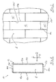
- Fig. 1 is a panel according to the invention generally designated 10.
- the panel 10 is formed as a rectangular panel and comprises two long sides 10a and 10b and two short sides 10c and 10d, which are each arranged in pairs opposite one another.
- the panel 10 is provided on both the long sides 10a and 10b as well as on the short sides 10c and 10d with coupling means which the connection of the panel 10 with in the longitudinal direction L or in the transverse direction Q adjacent panels 10 ', 10 ",. .. serve (see Fig. 2 ).
- the coupling means 12 are formed essentially in the form of a groove 12a provided on the long side 10a and a spring 12b provided on the long side 10b, which together form the coupling means of the long side, and a groove 12c provided on the short side 10c and one on the short side 10d provided spring 12d, which together form the coupling means of the short side.
- These coupling means 12 may be in different Variants of which with reference to the Fig. 3 to 6 will be explained in more detail below.
- Fig. 3 On the one hand, it can be interpreted as showing, at the bottom left in a first perspective view, the groove edge 10a or 10c and at the top right in a second perspective view the spring edge 10b or 10d of the same panel 10.
- the panels joined together to form a lining covering are identically formed, they can also be interpreted as meaning that the adjoining edges 10b, 10a 'or 10c, 10d "of two adjacent identically formed panels 10, 10' and 10, respectively , 10 "represents (see Fig. 2 ).
- Fig. 3 illustrated embodiment is a tongue and groove profile, which can be connected by interlocking two adjacent panels 10 and 10 'and 10 " Fig. 3 left Nutpaneel 10 lie flat on the ground, while the in Fig. 3 right spring panel 10 'or 10 "is fed laterally in an angled relative to the horizontal position until its spring 12b, 12d engages in the groove 12a, 12c of the panel 10.
- the two panels 10 and 10 'or 10 "provided by pivoting down the spring panel 10', 10" are engaged with each other in the illustrated embodiment, the locking means 14 are on the groove side 12a, 12c of the panel of a recess 14a formed in the upper surface of the lower, the groove 12 a, 12 c bounding lip 16.
- the Locking means 14 formed by a projection 14 b, which is provided on the underside of the spring 12 b, 12 d.
- the engagement of the coupling means 12 prevents a relative movement of the two panels 10 in the vertical direction H (see Fig. 1 ), that is, in a direction orthogonal to the panel plane or Begeh formation E of the panel 10 extending direction, while the interaction of the locking means 14 prevents relative movement of the two panels 10 in a panel plane E and orthogonal to the respective side edge 12a to 12d extending direction.
- the panel plane E is thereby spanned by the longitudinal direction L (direction of the long sides 10a and 10b) and the transverse direction Q (direction of the short sides 10c and 10d) of the panel 10.
- the panels 10 according to the invention additionally have a roughening 18, which at least complicates a relative movement of two interconnected panels 10 in the longitudinal direction of the respective side edge 10a / 10b, 10c / 10d.
- a roughening 18 which at least complicates a relative movement of two interconnected panels 10 in the longitudinal direction of the respective side edge 10a / 10b, 10c / 10d.
- at least one surface portion of the abutting surfaces of the coupling means 12 and the locking means 14 is provided with such a roughening 18.
- this is on the one hand the base 14a1 of the recess 14a of the in Fig. 3 Nutpaneels shown on the left and the top surface 14b1 of the projection 14b of in Fig. 3 right illustrated spring panel.
- the two aforementioned surfaces 14a1 and 14b1 abut against each other in the connected state of two adjacent panels, thus interacting with their respective roughnesses, thereby effectively increasing the longitudinal friction of the respective side edges 10a / 10b, 10c / 10d.
- the surface 14a1 and 14b1 of the panel 10 therefore form "complementary" surfaces.
- the rugosities 18 extend in the longitudinal direction of the two side edges, preferably over their entire length, while they, as in Fig. 3 shown, are provided in the circumferential direction U only on a part of the boundary surface of the groove or the spring. The latter, however, has mainly manufacturing reasons.
- the roughenings 18 are each formed by a toothing, the teeth 18a in the longitudinal direction of the respective side edge 10a / 10b, 10c / 10d successive (“tooth follower"), each individual tooth substantially in the circumferential direction U, ie orthogonal to the longitudinal direction of the respective side edge extends ("Zahnerstreckungsraum").
- the toothing 18 can be formed, for example, by impressing the teeth 18a in the base 14a1 of the recess 14a and in the head surface 14b1 of the projection 14b.
- a rotating tool 20 or 22 with the surfaces 14a1 and 14b1 is brought into engagement, the peripheral surface 20a and 22a has one of the teeth to be formed 18 corresponding counter-toothing.
- a further tool 24 is shown, which corresponds in construction and function of the tools 20 and 22, but is arranged such that it provides an oblique boundary surface 14a2 of the recess 14a with a toothing. It should also be noted that at the in Fig. 4 shown right spring panel no analog gear tool for the local inclined surface 14b2 is provided. Nevertheless, even the one-sided provision of a toothing can further increase the friction between the two panels.
- FIG. 5 and 6 a non-inventive illustration example is shown, which essentially according to the embodiment Fig. 3 and 4 equivalent. Therefore, in the Fig. 5 and 6 Analog parts provided with the same reference numerals as in Fig. 3 and 4 , but increased by the number 100. In addition, the Fig. 5 and 6 in the following will be described only insofar as they differ from the above-described embodiment, the description of which is hereby expressly referred to.
- panel 110 differs from the panel 10 according to Fig. 3 and 4 on the one hand, that the coupling means 112 formed on the side edges 110a-110d are not formed so that two adjacent panels can be connected to each other by angling the spring panel into the groove panel, but the panels 110 are connected by a substantially planar telescoping parallel to the panel plane E. become.
- the locking means 114 are in this case formed by a projection 114a at the free end of the groove 112a, 112c limiting lower lip 116 and by a recess 114b in the region of the transition of the spring 112b, 112d in the panel 110.
- both the groove 112a, 112c and the spring 112b, 112d provided with a roughening 118, on the one hand to an upper boundary surface 116a of the lower lip 116 and the other to a lower boundary surface 122 of the spring 112b, 112d.
- the roughenings 118 are formed in the present case of particles 118a, which by means of a spray tool 128 or 130 (see Fig. 6 ) can be applied to the surfaces 116a and 126, preferably using an adhesion promoter, which holds the particles 118a after drying on the surfaces 116a, 126.
- a solvent can also be applied to the surfaces 116a and 126, which at least solves a wood material used for forming the panels 110, for example solid wood, MDF or the like, so that individual wood fibers are at least partially made loosen the material composite and protrude from the surface after drying of the treatment agent.
- a wood material used for forming the panels 110 for example solid wood, MDF or the like
- Fig. 5 118a denotes the wood fibers protruding from the surfaces 116a and 126a.
- the panels 10, 110 can be made of any material, such as a wood material, such as solid wood boards, MDF boards, chipboard or the like, or even of compact laminate, plastic and the like suitable panel materials.
- the panels are to be used as floor panels, they can, as in Fig. 4 and 6 each at the panel 10 shown at the bottom left, 110, have a core 10e, 110e, which is formed for example as MDF board (medium-density fiberboard), said core 10e, 110e on its Begeh Type E a decorative layer 10f, 110f and at its the loading side E opposite, on the ground Overlying bottom B with a leveling layer 10g, 110g is glued.
- the decorative layer 10f, 110f may, for example, comprise one or more layers of printed paper impregnated with synthetic resin.
- the compensating layer 10g, 100g may also be formed by such a laminate layer comprising a plurality of paper layers.
- the groove 112a, 112c and the spring 112b, 112d need not necessarily be formed directly from the material of the core 110e. Rather, it is, as in Fig. 6 indicated by dashed lines, also possible to inject into a prepared in the side surface 110a to 110d recess 150 a suitable material, such as plastic, a wood extrudate or the like, and cure there and the groove 112a, 112c and the spring 112b, 112d thereafter to be trained by machining.
- a suitable material such as plastic, a wood extrudate or the like
Landscapes
- Engineering & Computer Science (AREA)
- Architecture (AREA)
- Civil Engineering (AREA)
- Structural Engineering (AREA)
- Floor Finish (AREA)
- Finishing Walls (AREA)
- Connection Of Plates (AREA)
- Laminated Bodies (AREA)
- Glass Compositions (AREA)
- Dry Shavers And Clippers (AREA)
- Vehicle Interior And Exterior Ornaments, Soundproofing, And Insulation (AREA)
- Diaphragms For Electromechanical Transducers (AREA)
Description
- Die Erfindung betrifft ein Verkleidungspaneel mit zwei Paaren von einander gegenüberliegenden Seitenrändern, wobei wenigstens ein Seitenränder-Paar mit Kopplungsmitteln versehen ist, welche im Wesentlichen in Form einer Nut und einer Feder ausgebildet sind und sich längs des jeweiligen Seitenrands erstrecken.
- Derartige Verkleidungspaneele sind allgemein bekannt. Beispielsweise sei auf die
EP 1 036 244 B1 verwiesen. - Diese Paneele werden üblicherweise dadurch hergestellt, dass man im Wesentlichen quaderförmige Rohpaneele, d.h. Rohpaneele, deren den Seitenrändern zugeordnete Seitenflächen im Wesentlichen orthogonal zur Begehfläche verlaufen, spanabhebend bearbeitet, beispielsweise durch Fräsen, um an wenigstens einem der Seitenflächen-Paare die Kopplungsmittel herauszubilden, und zwar in Form einer Nut im Bereich der einen Seitenfläche sowie einer Feder im Bereich der anderen Seitenfläche. Ziel dieser spanabhebenden Bearbeitung ist es dabei stets, möglichst glatte Oberflächen zu erzielen, um beim Verlegen der Verkleidungspaneele zwei über Nut und Feder miteinander verbundene Paneele in Längsrichtung des betreffenden Seitenrands relativ zueinander verschieben zu können.
- Ein Problem, mit welchem derartige Verkleidungspaneele in der Praxis stets zu kämpfen haben, sind die jahreszeitlich bedingten Schwankungen der relativen Luftfeuchtigkeit. Während Zeiten hoher relativer Luftfeuchtigkeit dehnen sich die Verkleidungspaneele aufgrund von Quellung aus, während sie aufgrund der niedrigeren relativen Luftfeuchtigkeit während der Heizungsperiode im Winter schrumpfen. Dieses Quellen und Schrumpfen führt selbst dann zur Bildung von Spalten zwischen aneinander angrenzenden Paneelen, wenn die Kopplungsmittel der Verkleidungspaneele, wie dies bei vielen derzeit auf dem Markt erhältlichen Typen von Verkleidungspaneelen üblich ist, mit integrierten Verriegelungsmitteln ausgebildet sind, welche sich in Längsrichtung des jeweiligen Seitenrands des Verkleidungspaneels erstrecken und einer Relativbewegung der beiden Paneele in einer in der Paneelebene und orthogonal zum jeweiligen Seitenrand verlaufenden Richtung versuchen entgegenzuwirken. Als weitere Ursachen für die Bildung von Spalten sind die einwirkungen von statischen und mechanisch-dynamischen Belastungen zu nennen, wie sie auf den Boden beispielsweise von schweren Einrichtungsgegenständen oder durch dessen Begehen ausgeübt werden. Bei rechteckigen Verkleidungspaneelen zeigt sich dieses Spaltenbildungsproblem insbesondere an den Kurzseiten der Paneele. Besonders stark tritt das Spaltenbildungsproblem zudem dann auf, wenn die Paneele, wie heutzutage üblich, auf dem Untergrund frei schwimmend verlegt sind, d.h. mit dem Untergrund nicht durch gesonderte Verbindungsmittel verbunden sind, und nicht miteinander verklebt sind.
- Zur Verhinderung von Spaltenbildung wurde in der
EP 0 843 763 A1 , derEP 1 024 234 A1 und derEP 1 026 341 A1 ein Verkleidungspaneel vorgeschlagen, bei welchem im verbundenen Zustand zweier Paneele die die Nut des einen Paneels begrenzende untere Lippe gegen die Feder des jeweils anderen Paneels mit einer Vorspannkraft andrückt. Dabei wird diese Vorspannkraft durch eine dauerhafte Auslenkung der unteren Lippe aus ihrer Ruhelage, die sie im unverbundenen Zustand der beiden Paneele einnimmt, erzeugt. Diese dauerhafte Auslenkung führt zu einer ständigen mechanischen Belastung und allmählichen Ermüdung des Paneelmaterials. - Die
US-B1-6 682 254 offenbart ein Verkleidungspaneel mit zwei Paaren von einander gegenüberliegenden Seitenrändern, welche mit Kopplungsmitteln aus Nut und Feder ausgebildet sind. Die Federabschnitte tragen in Paneellängsrichtung verlaufende Rippen, welche beim Zusammenfügen der Paneele einen Zwischenraum zwischen Nut und Feder in zwei Teilräume unterteilen. Durch diese Teilräume kann eine ungleichmäßige Verteilung von Klebstoff während der Montage ausgeglichen werden. - Ferner offenbart die
WO 98/22677 A - Die
WO 03/074814 - Eine weitere Kopplungsstruktur zur Verbindung von Fußbodenpaneelen ist aus der
US 2001/024707 A1 bekannt und umfasst zusätzlich zu den Nut-Feder Kopplungsmitteln auf der Nutseite des Verkleidungspaneels eine konvexe Stufe sowie an der Federseite des Paneels eine entsprechend komplementär geformte konkave Vertiefung. Die Kontaktflächen von Stufe und Vertiefung tragen jeweils eine Beschichtung zur Erhöhung der Rauigkeit, zum Beispiel Partikel, einen Gummibelag oder dergleichen. - Die
DE 100 34 409 A1 offenbart Verkleidungspaneele, welche mittels eines Verbindungselements zu verbinden sind, welches jeweils in aneinanderstoßende Seitenränder zweier benachbarter Paneele eingeführt ist. Ein fester Halt des Verbindungselements in den Paneelen wird durch Widerhaken des Verbindungselements gewährleistet. - Die
FR 1 483 017 A - Es ist Aufgabe der vorliegenden Erfindung, ein Verkleidungspaneel der eingangs genannten Art bereitzustellen, bei welchem der Bildung von Spalten zwischen zwei miteinander verbundenen Paneelen unter Verzicht auf das Vorsehen einer Vorspannkraft entgegengewirkt werden kann.
- Diese Aufgabe wird erfindungsgemäß durch ein Verkleidungspaneel nach Anspruch 1 gelöst.
- Unter der "Begrenzungsfläche" gemäß den Ansprüchen wird dabei im Zusammenhang mit der vorliegenden Erfindung diejenige Fläche verstanden, die von der Seitenfläche des jeweiligen Seitenrands ausgeht, die Nut mit einer in die Nut hinein weisenden Flächennormalen bzw. die Feder mit einer von der Feder weg weisenden Flächennormalen umläuft und auf der anderen Seite der Nut bzw. der Feder wieder an der Seitenfläche des Seitenrands endet.
- Durch das Vorsehen der erfindungsgemäßen Aufrauhung wird die Reibung zwischen der Nut des einen Paneels und der Feder des anderen Paneels erhöht, sodass eine Relatiwerlagerung der beiden miteinander verbundenen Paneele in Längsrichtung der Nut bzw. der Feder erschwert ist. Hierdurch wird auch der Spaltbildung an der orthogonal zu dieser Längsrichtung verlaufenden Paneelseite entgegengewirkt. D.h. dann, wenn das Verkleidungspaneel ein rechteckiges Verkleidungspaneel mit einer Kurzseite und einer Langseite ist, kann der Spaltenbildung an der Kurzseite des Paneels dadurch entgegengewirkt werden, dass man zumindest an der Langseite wenigstens einen Abschnitt der Begrenzungsfläche von Nut oder/und Feder mit einer Aufrauhung versieht. Selbstverständlich hat auch das Vorsehen einer Aufrauhung im Bereich der Nut oder/und der Feder der Kurzseite des Paneels eine Minderung der Neigung zur Spaltenbildung an der Langseite des Paneels zur Folge.
- Im Hinblick auf die Erzielung einer möglichst hohen Reibung ist es bevorzugt, wenn sich der mit der Aufrauhung versehene wenigstens eine Abschnitt der Begrenzungsfläche sowohl über die im Wesentlichen gesamte Länge des jeweiligen Seitenrands als auch in Umfangsrichtung der Begrenzungsfläche über den im Wesentlichen gesamten Umfang der Begrenzungsfläche erstreckt. Nicht zuletzt aus fertigungstechnischen Gründen kann es jedoch auch wünschenswert sein, dass der mit der Aufrauhung versehene wenigstens eine Abschnitt der Begrenzungsfläche sich lediglich über einen Teil der Länge des jeweiligen Seitenrands oder/und in Umfangsrichtung lediglich über einen Teil der Begrenzungsfläche erstreckt.
- Die Reibung zwischen der Begrenzungsfläche der Nut und der korrespondierenden Begrenzungsfläche der Feder wird weiter dadurch erhöht, dass sowohl wenigstens ein Abschnitt der Begrenzungsfläche der Nut als auch wenigstens ein Abschnitt der Begrenzungsfläche der Feder mit einer Aufrauhung versehen sind und diese Aufrauhungen wenigstens zum Teil an zueinander komplementären Abschnitten der Begrenzungsflächen von Nut und Feder vorgesehen sind. Als "komplementär" im Sinne dieses Anspruchs sind zwei Abschnitte der Begrenzungsflächen von Nut bzw. Feder ein und desselben Paneels dann anzusehen, wenn bei Verbindung zweier identischer Paneele der mit einer Aufrauhung versehene Abschnitt der Nut des einen Paneels und der mit einer Aufrauhung versehene Abschnitt der Feder des anderen Paneels im verbundenen Zustand dieser beiden Paneele aneinander anliegen.
- Die Aufrauhung ist erfindungsgemäß von einer Verzahnung gebildet. Zur Erzielung einer möglichst hohen Reibung zwischen zwei miteinander verbundenen Paneelen ist dabei vorgesehen, dass die Zahnfolgerichtung der Verzahnung im Wesentlichen in Längsrichtung des jeweiligen Seitenrands verläuft, während die Zahnerstreckungsrichtung im Wesentlichen in Umfangsrichtung der Nut bzw. der Feder verläuft. Unter der "Zahnfolgerichtung" wird dabei diejenige Richtung verstanden, in welcher die Zähne der Verzahnung aufeinander folgen; bei einem herkömmlichen Zahnrad also die Umfangsrichtung des Zahnrads. Als "Zahnerstreckungsrichtung" wird hingegen diejenige Richtung verstanden, in der sich der einzelne Zahn erstreckt; bei einem herkömmlichen Zahnrad mit Geradverzahnung also die Achsrichtung. Die Verzahnung kann beispielsweise durch eine im Wesentlichen spanlose Bearbeitung gebildet sein, etwa durch Eindrücken, Einkerben oder dergleichen. Zusätzlich oder alternativ ist es jedoch auch möglich, dass die Verzahnung durch eine spanende Bearbeitung zu bilden, beispielsweise durch Stechen, Fräsen oder dergleichen. In beiden Alternativen zur Herstellung der Verzahnung ist es jedoch vorteilhaft, ein Werkzeug einzusetzen, dessen Rotationsgeschwindigkeit derart auf die Vorschubgeschwindigkeit des Paneels abgestimmt ist, dass seine Umfangsgeschwindigkeit im Wesentlichen mit der Vorschubgeschwindigkeit des Paneels übereinstimmt.
- Zusätzlich zur Ausbildung des aufgerauhten Abschnitts als Verzahnung kann wenigstens ein mit einer Aufrauhung versehener Abschnitt von einer Mehrzahl von Holzfasern gebildet sein, welche aus der Oberfläche des jeweiligen Abschnitts der Begrenzungsfläche hervorstehen. Um dieses Aufstellen der Fasern zu erreichen, kann die Oberfläche mit einem Mittel behandelt sein, beispielsweise mit einem wasserverdünnbaren Lack (wie einer weichmacherfreien wässrigen Copolymerisatdispersion), welches die Fasern zumindest teilweise aus ihrem Materialverbund, beispielsweise Vollholz, MDF oder einem anderen Holzwerkstoff, herauslöst, aufstellt und fixiert.
- Zusätzlich kann wenigstens ein mit einer Aufrauhung versehener Abschnitt von einer Mehrzahl von Partikeln gebildet sein, welche auf die Oberfläche des jeweiligen Abschnitts der Begrenzungsfläche aufgebracht sind. Als diese Partikel kommen beispielsweise Partikel aus mikronisiertem Polypropylenwachs in Betracht, welche eine Größe von zwischen etwa 30 µm und 75 µm aufweisen. Ferner können diese Partikel mittels eines Haftvermittlers, beispielsweise einem wasserverdünnbaren Lack (etwa einer weichmacherfreien wässrigen Copolymerisatdispersion) mit der Oberfläche des jeweiligen Abschnitts der Begrenzungsfläche verbunden sein.
- Wie vorstehend bereits angedeutet, kann zumindest ein Kern des Paneels aus einem Holzwerkstoff, beispielsweise Vollholz, einer Spanplatte, einer MDF-Platte oder dergleichen, gebildet sein. Grundsätzlich ist es jedoch auch möglich, die erfindungsgemäßen Prinzipien bei anderen Werkstoffen einzusetzen, beispielsweise Kompaktlaminat, Kunststoff oder dergleichen.
- Wie vorstehend ebenfalls bereits erwähnt, können die Kopplungsmittel mit integrierten Verriegelungsmitteln ausgebildet sein, welche sich in Längsrichtung des jeweiligen Seitenrands erstrecken. Diese Verriegelungsmittel können dabei beispielsweise einstückig aus dem Kernmaterial gebildet sein. Grundsätzlich ist es jedoch auch denkbar, die Verriegelungsmittel oder/und die Kopplungsmittel in bzw. an einer mit dem Kern des Paneels verbundenen Kopplungseinheit auszubilden. Diese Kopplungseinheit kann beispielsweise dadurch mit dem Kern des Paneels verbunden sein, dass man ein geeignetes Material, beispielsweise Kunststoff, ein Holzextrudat oder dergleichen, in eine vorbereitete Vertiefung in der Seitenfläche des Paneels einspritzt und anschließend zur Bildung der Kopplungsmittel oder/und der Verriegelungsmittel materialabtragend bearbeitet. Alternativ ist es jedoch auch möglich, ein vorgefertigtes Teil mit daran vorgefertigten Kopplungsmitteln oder/und Verriegelungsmitteln in die vorbereitete Vertiefung einzulegen.
- In besonders vorteilhafter Weise kann die Erfindung dann eingesetzt werden, wenn das Verkleidungspaneel ein Fußbodenpaneel ist, und zwar insbesondere dann, wenn das Fußbodenpaneel zur schwimmenden Verlegung oder/und zu Verlegung ohne die Verwendung von Klebstoff zur Verbindung benachbarter Paneele bestimmt ist.
- Die Erfindung wird im Folgenden an Ausführungsbeispielen anhand der beigefügten Zeichnungen näher erläutert werden. Es stellt dar:
- Fig. 1
- eine Draufsicht auf ein erfindungsgemäßes Verkleidungs-paneel;
- Fig. 2
- eine Teildraufsicht auf einen aus einer Mehrzahl derartiger Verkleidungspaneele gebildeten Verkleidungsbelag;
- Fig.3
- eine perspektivische Darstellung des Nutendes und des Federendes eines erfindungsgemäß mit einer Aufrauhung versehenen Verkleidungspaneels;
- Fig. 4
- eine schematische Seitenansicht des Paneels gemäß
Fig. 3 zur Erläuterung des Verfahrens zur Ausbildung der Aufrauhung; und - Fig. 5 und 6
- Ansichten ähnlich
Fig. 3 und4 eines nicht erfindungsgemäßen Illustrationsbeispiels. - In
Fig. 1 ist ein erfindungsgemäßes Paneel ganz allgemein mit 10 bezeichnet. Das Paneel 10 ist als rechteckiges Paneel ausgebildet und umfasst zwei Langseiten 10a und 10b sowie zwei Kurzseiten 10c und 10d, die einander jeweils paarweise gegenüberliegend angeordnet sind. In dem dargestellten Ausführungsbeispiel ist das Paneel 10 sowohl an den Langseiten 10a und 10b als auch an den Kurzseiten 10c und 10d mit Kopplungsmitteln versehen, welche der Verbindung des Paneels 10 mit in Längsrichtung L oder in Querrichtung Q benachbarten Paneelen 10', 10", ... dienen (sieheFig. 2 ). - Die Kopplungsmittel 12 sind im Wesentlichen in Form einer an der Langseite 10a vorgesehenen Nut 12a und einer an der Langseite 10b vorgesehenen Feder 12b gebildet, die zusammen die Kopplungsmittel der Langseite bilden, sowie einer an der Kurzseite 10c vorgesehen Nut 12c und einer an der Kurzseite 10d vorgesehenen Feder 12d, die zusammen die Kopplungsmittel der Kurzseite bilden. Diese Kopplungsmittel 12 können in verschiedenen Varianten ausgeführt sein, von denen mit Bezug auf die
Fig. 3 bis 6 nachfolgend noch einige näher erläutert werden werden. Alle diese Kopplungsmittel 12 haben jedoch die gemeinsame Eigenschaft, dass einander zugeordnete Paare 12a/12b, 12c/12d von Nuten und Federn so ausgebildet sind, dass sie im verbundenen Zustand zweier identischer Paneele 10 Puzzleteil-artig, also vorspannungsfrei ineinander greifen, d.h. insbesondere ohne dass die untere Nutbegrenzungslippe dauerhaft aus ihrer Ruhelage ausgelenkt wäre. - Die Darstellung gemäß
Fig. 3 kann zum einen dahingehend interpretiert werden, dass sie links unten in einer ersten perspektivischen Ansicht den Nutrand 10a bzw. 10c und rechts oben in einer zweiten perspektivischen Ansicht den Federrand 10b bzw. 10d ein und desselben Paneels 10 zeigt. Da die zu einem Verkleidungsbelag zusammengefügten Paneele identisch ausgebildet sind, kann sie zum anderen aber auch dahingehend interpretiert werden, dass sie die aneinander angrenzende Ränder 10b, 10a' bzw. 10c, 10d" zweier aneinander angrenzender identisch ausgebildeter Paneele 10, 10' bzw. 10, 10" darstellt (sieheFig. 2 ). - Bei der in
Fig. 3 dargestellten Ausführungsform handelt es sich um ein Nut-Feder-Profil, welches durch Ineinanderwinkeln zweier benachbarter Paneele 10 und 10' bzw. 10" verbunden werden kann. Hierzu kann das inFig. 3 linke Nutpaneel 10 flach auf dem Boden aufliegen, während das inFig. 3 rechte Federpaneel 10' bzw. 10" in einer bezüglich der Horizontalen angewinkelten Stellung seitlich zugeführt wird, bis seine Feder 12b, 12d in die Nut 12a, 12c des Paneels 10 eingreift. Anschließend können die an den Kopplungsmitteln 12a, 12c bzw. 12b, 12d der beiden Paneele 10 und 10' bzw. 10" vorgesehenen Verriegelungsmittel 14 durch Herunterschwenken des Federpaneels 10', 10" miteinander in Eingriff gebracht werden. In dem dargestellten Ausführungsbeispiel sind die Verriegelungsmittel 14 dabei auf der Nutseite 12a, 12c der Paneele von einer Ausnehmung 14a gebildet, welche in der oberen Fläche der unteren, die Nut 12a, 12c begrenzenden Lippe 16 ausgebildet ist. Auf der Federseite des Paneels 10 sind die Verriegelungsmittel 14 von einem Ansatz 14b gebildet, der an der Unterseite der Feder 12b, 12d vorgesehen ist. - Im verbundenen Zustand zweier Paneele 10 verhindert der Eingriff der Kopplungsmittel 12 eine Relativbewegung der beiden Paneele 10 in Hochrichtung H (siehe
Fig. 1 ), d.h. in einer orthogonal zur Paneelebene bzw. Begehfläche E der Paneele 10 verlaufenden Richtung, während das Zusammenwirken der Verriegelungsmittel 14 eine Relativbewegung der beiden Paneele 10 in einer in der Paneelebene E und orthogonal zum jeweiligen Seitenrand 12a bis 12d verlaufenden Richtung unterbindet. Die Paneelebene E wird dabei von der Längsrichtung L (Richtung der Langseiten 10a und 10b) und der Querrichtung Q (Richtung der Kurzseiten 10c und 10d) der Paneele 10 aufgespannt. - Im Unterschied zu den Paneelen des Standes der Technik verfügen die erfindungsgemäßen Paneele 10 zusätzlich über eine Aufrauhung 18, welche eine Relativbewegung zweier miteinander verbundener Paneele 10 in Längsrichtung des jeweiligen Seitenrands 10a/10b, 10c/10d zumindest erschwert. Hierzu ist wenigstens ein Flächenabschnitt der aneinander anliegenden Oberflächen der Kopplungsmittel 12 und der Verriegelungsmittel 14 mit einer derartigen Aufrauhung 18 versehen. In dem in
Fig. 3 dargestellten Ausführungsbeispiel ist dies zum einen die Grundfläche 14a1 der Ausnehmung 14a des inFig. 3 links dargestellten Nutpaneels und die Kopffläche 14b1 des Ansatzes 14b des inFig. 3 rechts dargestellten Federpaneels. Man beachte, dass die beiden vorstehend genannten Flächen 14a1 und 14b1 im verbundenen Zustand zweier benachbarter Paneele aneinander anliegen und so ihre jeweiligen Aufrauhungen miteinander wechselwirken, wodurch die Reibung in Längsrichtung der jeweiligen Seitenränder 10a/10b, 10c/10d wirksam erhöht wird. Im Sinne der vorliegenden Anmeldung bilden die Fläche 14a1 und 14b1 des Paneels 10 daher "komplementäre" Flächen. - Die Aufrauhungen 18 erstrecken sich in Längsrichtung der beiden Seitenränder vorzugsweise über deren gesamte Länge, während sie, wie in
Fig. 3 dargestellt, in Umfangsrichtung U nur auf einem Teil der Begrenzungsfläche der Nut bzw. der Feder vorgesehen sind. Letzteres hat jedoch vornehmlich herstellungstechnische Gründe. - Wie in
Fig. 3 schematisch angedeutet ist, sind die Aufrauhungen 18 jeweils von einer Verzahnung gebildet, deren Zähne 18a in Längsrichtung des jeweiligen Seitenrands 10a/10b, 10c/10d aufeinander folgen ("Zahnfolgerichtung"), wobei sich jeder einzelne Zahn im Wesentlichen in Umfangsrichtung U, d.h. orthogonal zur Längsrichtung des jeweiligen Seitenrands erstreckt ("Zahnerstreckungsrichtung"). - Wie in
Fig. 4 schematisch dargestellt ist, kann die.Verzahnung 18 beispielsweise durch Eindrücken der Zähne 18a in die Grundfläche 14a1 der Ausnehmung 14a bzw. in die Kopffläche 14b1 des Ansatzes 14b ausgebildet werden. Hierzu wird ein rotierendes Werkzeug 20 bzw. 22 mit den Flächen 14a1 bzw. 14b1 in Eingriff gebracht, dessen Umfangsfläche 20a bzw. 22a eine der auszubildenden Verzahnung 18 entsprechende Gegenverzahnung aufweist. Zudem ist darauf zu achten, dass sich das Werkzeug 20 bzw. 22 synchron zur Bewegung des Paneels 10 dreht, d.h. derart, dass seine Umfangsgeschwindigkeit bei Drehung um die Achse 20b bzw. 22b der Vorschubgeschwindigkeit des Paneels 10 in Richtung des jeweiligen Seitenrands 10a bis 10d entspricht. - In
Fig. 4 ist ferner ein weiteres Werkzeug 24 dargestellt, welches in Aufbau und Funktion den Werkzeugen 20 und 22 entspricht, jedoch derart angeordnet ist, dass es eine schräge Begrenzungsfläche 14a2 der Ausnehmung 14a mit einer Verzahnung versieht. Zu beachten ist ferner, dass an dem inFig. 4 rechts dargestellten Federpaneel kein analoges Verzahnungswerkzeug für die dortige Schrägfläche 14b2 vorgesehen ist. Gleichwohl kann bereits das einseitige Vorsehen einer Verzahnung die Reibung zwischen den beiden Paneelen weiter erhöhen. - In den
Fig. 5 und6 ist ein nicht erfindungsgemäßes Illustrationsbeispiel dargestellt, welches im wesentlichen der Ausführungsform gemäßFig. 3 und4 entspricht. Daher sind in denFig. 5 und6 analoge Teile mit den gleichen Bezugszeichen versehen wie inFig. 3 und4 , jedoch vermehrt um die Zahl 100. Darüber hinaus werden dieFig. 5 und6 im Folgenden nur insoweit beschrieben werden, als sie sich von der vorstehend erläuterten Ausführungsform unterscheiden, auf deren Beschreibung hiermit ansonsten ausdrücklich verwiesen sei. - Das in den
Fig. 5 und6 dargestellte Paneel 110 unterscheidet sich von dem Paneel 10 gemäßFig. 3 und4 zum einen dadurch, dass die an den Seitenrändern 110a - 110d ausgebildeten Kopplungsmittel 112 nicht derart ausgebildet sind, dass zwei benachbarte Paneele durch Einwinkeln des Federpaneels in das Nutpaneel miteinander verbunden werden können, sondern die Paneele 110 durch im Wesentlichen planares Aufeinanderzuschieben parallel zur Paneelebene E verbunden werden. Die Verriegelungsmittel 114 sind in diesem Fall von einem Ansatz 114a am freien Ende der die Nut 112a, 112c begrenzenden unteren Lippe 116 und von einer Ausnehmung 114b im Bereich des Übergangs der Feder 112b, 112d in das Paneel 110 gebildet. Daher wird beim Einführen der Feder 112b, 112d in die Nut 112a, 112c die untere Lippe 116 so lange ausgelenkt, d.h. nach unten verbogen, bis der Vorsprung 114a in die Ausnehmung 114b einrasten kann. In Folge dieses Einrastens kehrt die untere Lippe 116 wieder in ihre inFig. 5 dargestellte Ruhelage zurück, in welcher sie frei von jeglicher mechanischer Verformung ist. - Auch in dem in den
Fig. 5 und6 dargestellten Illustrationsbeispiel sind sowohl die Nut 112a, 112c als auch die Feder 112b, 112d mit einer Aufrauhung 118 versehen, und zwar zum einen an einer oberen Begrenzungsfläche 116a der unteren Lippe 116 und zum anderen an einer unteren Begrenzungsfläche 122 der Feder 112b, 112d. Die Aufrauhungen 118 sind im vorliegenden Fall von Partikeln 118a gebildet, die mittels eines Sprühwerkzeugs 128 bzw. 130 (sieheFig. 6 ) auf die Flächen 116a und 126 aufgebracht werden können, vorzugsweise unter Verwendung eines Haftvermittlers, der die Partikel 118a nach seinem Abtrocknen auf den Flächen 116a, 126 hält. - Festzuhalten ist noch, dass es grundsätzlich auch denkbar ist, lediglich eine der beiden komplementären Flächen 116a, 126 mit solchen aufgesprühten Partikeln zu versehen, um eine höhere Reibung zwischen den beiden Paneelen 110 zu erreichen. Darüber hinaus ist es denkbar, derartige Partikel auch auf die in
Fig. 5 nicht sichtbaren Flächen an der unteren Seite der oberen Nutbegrenzungslippe 132 als auch an der oberen Seite der Feder 112b, 112d aufzutragen. - Anhand der schematischen Darstellungen gemäß
Fig. 5 und6 soll nach-folgend auch noch eine weitere alternative Aufrauhung erläutert werden, welche nicht Teil der Erfindung bildet. - Und zwar kann mittels der Sprühwerkzeuge 128 und 130 auch ein Lösungsmittel auf die Flächen 116a und 126 aufgebracht werden, welches einen zur Bildung der Paneele 110 verwendeten Holzwerkstoff, beispielsweise Vollholz, MDF oder dergleichen, zumindest so weit anlöst, dass sich einzelne Holzfasern zumindest teilweise aus dem Werkstoffverbund lösen und nach dem Abtrocknen des Behandlungsmittels aus der Oberfläche hervorstehen. In diesem Fall sind in
Fig. 5 mit 118a die aus den Oberflächen 116a und 126a hervorstehenden Holzfasern bezeichnet. - Nachzutragen ist noch Folgendes:
- Die Paneele 10, 110 können aus einem beliebigen Werkstoff gefertigt sein, beispielsweise einem Holzwerkstoff, wie beispielsweise Vollholzbrettern, MDF-Platten, Spanplatten oder dergleichen, oder aber auch aus Kompaktlaminat, Kunststoff und dergleichen geeigneten Paneelmaterialien.
- Falls die Paneele als Fußbodenpaneele eingesetzt werden sollen, können sie, wie in
Fig. 4 und6 jeweils an dem links unten dargestellten Paneel 10, 110 angedeutet ist, einen Kern 10e, 110e aufweisen, der beispielsweise als MDF-Platte (mitteldichte Faserplatte) ausgebildet ist, wobei dieser Kern 10e, 110e an seiner Begehfläche E eine Dekorschicht 10f, 110f und an seiner der Begehseite E entgegengesetzten, auf dem Boden aufliegenden Unterseite B mit einer Ausgleichsschicht 10g, 110g beklebt ist. Die Dekorschicht 10f, 110f kann beispielsweise eine oder mehrere Lagen bedruckten Papiers umfassen, die mit Kunstharz getränkt ist bzw. sind. In analoger Weise kann auch die Ausgleichsschicht 10g, 100g von einer derartigen, mehrere Papierlagen umfassenden Laminatschicht gebildet sein. - Die Nut 112a, 112c bzw. die Feder 112b, 112d brauchen nicht notwendigerweise unmittelbar aus dem Material des Kerns 110e gebildet zu sein. Vielmehr ist es, wie in
Fig. 6 gestrichelt angedeutet ist, auch möglich, in eine in der Seitenfläche 110a bis 110d vorbereitete Ausnehmung 150 ein geeignetes Material, beispielsweise Kunststoff, ein Holzextrudat oder dergleichen, einzuspritzen und dort aushärten zu lassen und die Nut 112a, 112c bzw. die Feder 112b, 112d anschließend durch spanende Bearbeitung auszubilden.
Claims (13)
- Verkleidungspaneel (10) mit zwei Paaren von einander gegenüberliegenden Seitenrändern (10a-10d), wobei wenigstens ein Seitenränder-Paar mit Kopplungsmitteln (12) versehen ist, welche im Wesentlichen in Form einer Nut (12a, 12c) und einer Feder (12b, 12d) ausgebildet sind und sich längs des jeweiligen Seitenrands erstrecken, wobei wenigstens ein Abschnitt (14a1) der Begrenzungsfläche der Nut (12a, 12c) und wenigstens ein Abschnitt (14b1) der Begrenzungsfläche der Feder (12b, 12d) mit einer Aufrauhung (18) versehen ist, wobei die mit einer Aufrauhung versehenen Abschnitte (14a1,14b1) zueinander komplementär sind,
dadurch gekennzeichnet, dass die Aufrauhung (18) in Form einer Verzahnung (18) gebildet ist, wobei die Zahnfolgerichtung der Verzahnung (18) im Wesentlichen in Längsrichtung (L bzw. Q) des jeweiligen Seitenrands (10a-10d) verläuft, während die Zahnerstreckungsrichtung im Wesentlichen in Umfangsrichtung (U) der Nut (12a, 12c) bzw. der Feder (12b, 12d) verläuft, und wobei im verbundenen Zustand des Paneels mit einem weiteren identischen Paneel die komplementären Abschnitte (14a1,14b1) aneinander anliegen und miteinander in Eingriff stehen. - Verkleidungspaneel nach Anspruch 1,
dadurch gekennzeichnet, dass die Verzahnung (18) durch eine im Wesentlichen spanlose Bearbeitung gebildet ist, beispielsweise durch Eindrücken, Einkerben oder dergleichen. - Verkleidungspaneel nach einem der Ansprüche 1 oder 2,
dadurch gekennzeichnet, dass die Verzahnung (18) durch eine spanabhebende Bearbeitung gebildet ist, beispielsweise Stechen, Fräsen oder dergleichen. - Verkleidungspaneel nach einem der Ansprüche 1 bis 3,
dadurch gekennzeichnet, dass dann, wenn es ein rechteckiges Verkleidungspaneel mit einer Kurzseite (10c, 10d) und einer Langseite (10a, 10b) ist, zumindest an der Langseite (10a, 10b) wenigstens ein Abschnitt (14a1, 14b1) der Begrenzungsfläche von Nut oder/und Feder mit einer Aufrauhung (18) versehen ist. - Verkleidungspaneel nach einem der Ansprüche 1 bis 4,
dadurch gekennzeichnet, dass sich der mit der Aufrauhung(18) versehene wenigstens eine Abschnitt (14a1, 14b1) der Begrenzungsfläche lediglich über einen Teil der Länge des jeweiligen Seitenrands erstreckt. - Verkleidungspaneel nach einem der Ansprüche 1 bis 4,
dadurch gekennzeichnet, dass sich der mit der Aufrauhung(18) versehene wenigstens eine Abschnitt (14a1, 14b1) der Begrenzungsfläche über die im Wesentlichen gesamte Länge des jeweiligen Seitenrands erstreckt. - Verkleidungspaneel nach einem der Ansprüche 1 bis 6,
dadurch gekennzeichnet, dass sich der mit der Aufrauhung (18) versehene wenigstens eine Abschnitt (14a1, 14b1) der Begrenzungsfläche in Umfangsrichtung (U) der Begrenzungsfläche lediglich über einen Teil des Umfangs der Begrenzungsfläche erstreckt. - Verkleidungspaneel nach einem der Ansprüche 1 bis 6,
dadurch gekennzeichnet, dass sich der mit der Aufrauhung (18) versehene wenigstens eine Abschnitt (14a1, 14b1) der Begrenzungsfläche in Umfangsrichtung (U) der Begrenzungsfläche über den im Wesentlichen gesamten Umfang der Begrenzungsfläche erstreckt. - Verkleidungspaneel nach einem der Ansprüche 1 bis 8,
dadurch gekennzeichnet, dass zumindest ein Kern (10e) des Paneels (10) aus einem Holzwerkstoff, beispielsweise Vollholz, einer Spanplatte, einer MDF-Platte oder dergleichen, oder/und aus Kompaktlaminat oder/und aus Kunststoff gefertigt ist. - Verkleidungspaneel nach einem der Ansprüche 1 bis 9,
dadurch gekennzeichnet, dass die Kopplungsmittel (12) mit integrierten Verriegelungsmitteln (14) ausgebildet sind, welche sich in Längsrichtung (L bzw. Q) des jeweiligen Seitenrands (10a-10d) erstrecken. - Verkleidungspaneel nach Anspruch 10,
dadurch gekennzeichnet, dass die Verriegelungsmittel (14) einstückig aus dem Material des Kerns (10e) gefertigt sind. - Verkleidungspaneel nach einem der Ansprüche 1 bis 11,
dadurch gekennzeichnet, dass die Kopplungsmittel (112) oder/und die Verriegelungsmittel (114) in bzw. an einer mit dem Kern (110e) des Paneels (110) verbundenen Kopplungseinheit (150) ausgebildet sind. - Verkleidungspaneel nach einem der Ansprüche 1 bis 12,
dadurch gekennzeichnet, dass es ein Fußbodenpaneel ist.
Priority Applications (3)
| Application Number | Priority Date | Filing Date | Title |
|---|---|---|---|
| EP09160400A EP2085534A1 (de) | 2004-11-10 | 2005-11-09 | Verkleidungspaneel |
| SI200530846T SI1809833T1 (sl) | 2004-11-10 | 2005-11-09 | Panel obloge |
| PL05802289T PL1809833T3 (pl) | 2004-11-10 | 2005-11-09 | Panel licowy |
Applications Claiming Priority (2)
| Application Number | Priority Date | Filing Date | Title |
|---|---|---|---|
| DE102004054368A DE102004054368A1 (de) | 2004-11-10 | 2004-11-10 | Verkleidungspaneel |
| PCT/EP2005/011988 WO2006050928A1 (de) | 2004-11-10 | 2005-11-09 | Verkleidungspaneel |
Related Child Applications (1)
| Application Number | Title | Priority Date | Filing Date |
|---|---|---|---|
| EP09160400A Division EP2085534A1 (de) | 2004-11-10 | 2005-11-09 | Verkleidungspaneel |
Publications (2)
| Publication Number | Publication Date |
|---|---|
| EP1809833A1 EP1809833A1 (de) | 2007-07-25 |
| EP1809833B1 true EP1809833B1 (de) | 2009-08-19 |
Family
ID=35515658
Family Applications (2)
| Application Number | Title | Priority Date | Filing Date |
|---|---|---|---|
| EP09160400A Withdrawn EP2085534A1 (de) | 2004-11-10 | 2005-11-09 | Verkleidungspaneel |
| EP05802289A Expired - Lifetime EP1809833B1 (de) | 2004-11-10 | 2005-11-09 | Verkleidungspaneel |
Family Applications Before (1)
| Application Number | Title | Priority Date | Filing Date |
|---|---|---|---|
| EP09160400A Withdrawn EP2085534A1 (de) | 2004-11-10 | 2005-11-09 | Verkleidungspaneel |
Country Status (18)
| Country | Link |
|---|---|
| US (1) | US8001741B2 (de) |
| EP (2) | EP2085534A1 (de) |
| JP (1) | JP5122971B2 (de) |
| CN (2) | CN100575638C (de) |
| AT (1) | ATE440189T1 (de) |
| AU (1) | AU2005303947B2 (de) |
| CA (1) | CA2586186C (de) |
| DE (2) | DE102004054368A1 (de) |
| DK (1) | DK1809833T3 (de) |
| ES (1) | ES2329267T3 (de) |
| HR (1) | HRP20090476T1 (de) |
| MX (1) | MX2007005540A (de) |
| PL (1) | PL1809833T3 (de) |
| PT (1) | PT1809833E (de) |
| RU (1) | RU2358073C2 (de) |
| SI (1) | SI1809833T1 (de) |
| UA (1) | UA88490C2 (de) |
| WO (1) | WO2006050928A1 (de) |
Families Citing this family (77)
| Publication number | Priority date | Publication date | Assignee | Title |
|---|---|---|---|---|
| SE515210C2 (sv) | 2000-04-10 | 2001-06-25 | Valinge Aluminium Ab | Låssystem för hopfogning av golvskivor samt golvskivor försedda med sådana låssystem och golv bildat av sådana golvskivor |
| US7086205B2 (en) | 1993-05-10 | 2006-08-08 | Valinge Aluminium Ab | System for joining building panels |
| SE512290C2 (sv) | 1998-06-03 | 2000-02-28 | Valinge Aluminium Ab | Låssystem för mekanisk hopfogning av golvskivor samt golvskiva försedd med låssystemet |
| US7386963B2 (en) | 1998-06-03 | 2008-06-17 | Valinge Innovation Ab | Locking system and flooring board |
| SE517478C2 (sv) | 1999-04-30 | 2002-06-11 | Valinge Aluminium Ab | Låssystem för mekanisk hofogning av golvskivor, golvskiva försedd med låssystemet samt metod för framställning av mekaniskt hopfogningsbara golvskivor |
| SE517183C2 (sv) | 2000-01-24 | 2002-04-23 | Valinge Aluminium Ab | Låssystem för mekanisk hopfogning av golvskivor, golvskiva försedd med låssystemet och metod för framställning av sådana golvskivor |
| SE518184C2 (sv) | 2000-03-31 | 2002-09-03 | Perstorp Flooring Ab | Golvbeläggningsmaterial innefattande skivformiga golvelement vilka sammanfogas med hjälp av sammankopplingsorgan |
| US20040211144A1 (en) * | 2001-06-27 | 2004-10-28 | Stanchfield Oliver O. | Flooring panel or wall panel and use thereof |
| US8028486B2 (en) | 2001-07-27 | 2011-10-04 | Valinge Innovation Ab | Floor panel with sealing means |
| SE525661C2 (sv) | 2002-03-20 | 2005-03-29 | Vaelinge Innovation Ab | System för bildande av dekorativa fogpartier och golvskivor därför |
| JP4472355B2 (ja) | 2002-04-03 | 2010-06-02 | ベーリンゲ、イノベイション、アクチボラグ | フロアボード用機械式係止システム |
| SE525657C2 (sv) | 2002-04-08 | 2005-03-29 | Vaelinge Innovation Ab | Golvskivor för flytande golv framställda av åtminstone två olika materialskikt samt halvfabrikat för tillverkning av golvskivor |
| US8850769B2 (en) | 2002-04-15 | 2014-10-07 | Valinge Innovation Ab | Floorboards for floating floors |
| US8375673B2 (en) * | 2002-08-26 | 2013-02-19 | John M. Evjen | Method and apparatus for interconnecting paneling |
| US7845140B2 (en) | 2003-03-06 | 2010-12-07 | Valinge Innovation Ab | Flooring and method for installation and manufacturing thereof |
| US7677001B2 (en) | 2003-03-06 | 2010-03-16 | Valinge Innovation Ab | Flooring systems and methods for installation |
| US7886497B2 (en) | 2003-12-02 | 2011-02-15 | Valinge Innovation Ab | Floorboard, system and method for forming a flooring, and a flooring formed thereof |
| US7516588B2 (en) | 2004-01-13 | 2009-04-14 | Valinge Aluminium Ab | Floor covering and locking systems |
| US20050166516A1 (en) | 2004-01-13 | 2005-08-04 | Valinge Aluminium Ab | Floor covering and locking systems |
| SE527570C2 (sv) | 2004-10-05 | 2006-04-11 | Vaelinge Innovation Ab | Anordning och metod för ytbehandling av skivformat ämne samt golvskiva |
| US7454875B2 (en) | 2004-10-22 | 2008-11-25 | Valinge Aluminium Ab | Mechanical locking system for floor panels |
| US7841144B2 (en) | 2005-03-30 | 2010-11-30 | Valinge Innovation Ab | Mechanical locking system for panels and method of installing same |
| US8215078B2 (en) | 2005-02-15 | 2012-07-10 | Välinge Innovation Belgium BVBA | Building panel with compressed edges and method of making same |
| US8061104B2 (en) | 2005-05-20 | 2011-11-22 | Valinge Innovation Ab | Mechanical locking system for floor panels |
| SE530653C2 (sv) | 2006-01-12 | 2008-07-29 | Vaelinge Innovation Ab | Fuktsäker golvskiva samt golv med ett elastiskt ytskikt omfattande ett dekorativt spår |
| SE533410C2 (sv) | 2006-07-11 | 2010-09-14 | Vaelinge Innovation Ab | Golvpaneler med mekaniska låssystem med en flexibel och förskjutbar tunga samt tunga därför |
| US7861482B2 (en) | 2006-07-14 | 2011-01-04 | Valinge Innovation Ab | Locking system comprising a combination lock for panels |
| DE102006051840A1 (de) * | 2006-08-09 | 2008-02-14 | Agepan-Tarkett Laminatepark Eiweiler Gmbh & Co. Kg | Befestigungssystem für tafelförmige Paneele |
| DE102006052081A1 (de) * | 2006-11-04 | 2008-05-08 | Agepan-Tarkett Laminatepark Eiweiler Gmbh & Co. Kg | Befestigungssystem für tafelförmige Paneele |
| US8689512B2 (en) | 2006-11-15 | 2014-04-08 | Valinge Innovation Ab | Mechanical locking of floor panels with vertical folding |
| US11725394B2 (en) | 2006-11-15 | 2023-08-15 | Välinge Innovation AB | Mechanical locking of floor panels with vertical folding |
| SE532607C2 (sv) * | 2006-11-15 | 2010-03-02 | Vaelinge Innovation Ab | Mekanisk låsning av golvpaneler med vertikal vikning |
| KR101468444B1 (ko) * | 2006-11-15 | 2014-12-03 | 뵈린게 이노베이션 에이비이 | 수직 폴딩을 구비하는 마루 패널들의 기계적인 잠금 |
| SE531111C2 (sv) | 2006-12-08 | 2008-12-23 | Vaelinge Innovation Ab | Mekanisk låsning av golvpaneler |
| US8353140B2 (en) | 2007-11-07 | 2013-01-15 | Valinge Innovation Ab | Mechanical locking of floor panels with vertical snap folding |
| WO2009061279A1 (en) | 2007-11-07 | 2009-05-14 | Välinge Innovation AB | Mechanical locking of floor panels with vertical snap folding and an installation method to connect such panels |
| EP2235285B1 (de) | 2008-01-31 | 2019-06-26 | Välinge Innovation AB | Mechanischer verschluss für bodenplatten |
| US8505257B2 (en) | 2008-01-31 | 2013-08-13 | Valinge Innovation Ab | Mechanical locking of floor panels |
| CN102066674B (zh) | 2008-05-15 | 2015-06-03 | 瓦林格创新股份有限公司 | 具有通过磁场启动的机械锁定系统的地板镶板及安装镶板的方法 |
| DE202008010555U1 (de) * | 2008-08-08 | 2009-12-17 | Akzenta Paneele + Profile Gmbh | Kunststoffpaneel mit Hakenprofil |
| US20100068451A1 (en) * | 2008-09-17 | 2010-03-18 | David Richard Graf | Building panel with wood facing layer and composite substrate backing layer |
| SG172871A1 (en) | 2009-01-30 | 2011-08-29 | Vaelinge Innovation Belgium Bvba | Mechanical lockings of floor panels and a tongue blank |
| EP3702549B1 (de) | 2010-01-12 | 2023-05-10 | Välinge Innovation AB | Satz von bodenpaneelen |
| US8234830B2 (en) | 2010-02-04 | 2012-08-07 | Välinge Innovations AB | Mechanical locking system for floor panels |
| BR112012018285B1 (pt) | 2010-02-04 | 2020-02-18 | Välinge Innovation AB | Conjunto de painéis de piso |
| WO2011127981A1 (en) | 2010-04-15 | 2011-10-20 | Spanolux N.V.- Div. Balterio | Floor panel assembly |
| US20120024347A1 (en) * | 2010-07-27 | 2012-02-02 | Tzy-Ying Lin | Solar package structure and method for fabricating the same |
| UA109938C2 (uk) | 2011-05-06 | 2015-10-26 | Механічна фіксуюча система для будівельних панелей | |
| UA114715C2 (uk) | 2011-07-05 | 2017-07-25 | Сералок Інновейшн Аб | Механічна фіксація панелей настилу підлоги до язичка з нанесеним шаром клею |
| US9725912B2 (en) | 2011-07-11 | 2017-08-08 | Ceraloc Innovation Ab | Mechanical locking system for floor panels |
| US8650826B2 (en) | 2011-07-19 | 2014-02-18 | Valinge Flooring Technology Ab | Mechanical locking system for floor panels |
| DE102012102339A1 (de) * | 2011-07-29 | 2013-01-31 | Hamberger Industriewerke Gmbh | Verbindung für elastische oder plattenförmige Bauelemente, Profilschieber und Fußbodenbelag |
| US8857126B2 (en) | 2011-08-15 | 2014-10-14 | Valinge Flooring Technology Ab | Mechanical locking system for floor panels |
| US8763340B2 (en) | 2011-08-15 | 2014-07-01 | Valinge Flooring Technology Ab | Mechanical locking system for floor panels |
| US8769905B2 (en) | 2011-08-15 | 2014-07-08 | Valinge Flooring Technology Ab | Mechanical locking system for floor panels |
| CN102373785A (zh) * | 2011-10-20 | 2012-03-14 | 宣建民 | 一种地板锁扣 |
| US9216541B2 (en) | 2012-04-04 | 2015-12-22 | Valinge Innovation Ab | Method for producing a mechanical locking system for building panels |
| US8596013B2 (en) | 2012-04-04 | 2013-12-03 | Valinge Innovation Ab | Building panel with a mechanical locking system |
| US20130313046A1 (en) * | 2012-05-24 | 2013-11-28 | John Birk | Adjustable length scaffolding and method therefor |
| US20140318895A1 (en) * | 2013-04-29 | 2014-10-30 | John Birk | Adjustable length scaffolding and method therefor |
| WO2014033628A1 (en) * | 2012-08-27 | 2014-03-06 | Pergo (Europe) Ab | Panel |
| AU2013348454C1 (en) | 2012-11-22 | 2017-11-09 | Ceraloc Innovation Ab | Mechanical locking system for floor panels |
| HUE060779T2 (hu) | 2013-06-27 | 2023-04-28 | Vaelinge Innovation Ab | Mechanikus rögzítõrendszerrel ellátott építõpanel |
| CN103758322A (zh) * | 2013-06-30 | 2014-04-30 | 江西南丰振宇实业集团有限公司 | 一种新型锁扣地板 |
| WO2015144726A1 (en) | 2014-03-24 | 2015-10-01 | Ivc N.V. | A set of mutually lockable panels |
| US9260870B2 (en) | 2014-03-24 | 2016-02-16 | Ivc N.V. | Set of mutually lockable panels |
| KR102386246B1 (ko) | 2014-05-14 | 2022-04-12 | 뵈린게 이노베이션 에이비이 | 기계식 록킹 시스템이 구비된 빌딩 패널 |
| US10246883B2 (en) | 2014-05-14 | 2019-04-02 | Valinge Innovation Ab | Building panel with a mechanical locking system |
| RU2584985C2 (ru) * | 2014-07-15 | 2016-05-27 | Александр Григорьевич Леонтьев | Стеновая ламельная панель |
| CN107002411B (zh) | 2014-11-27 | 2020-06-16 | 瓦林格创新股份有限公司 | 用于地板镶板的机械锁定系统 |
| JP6077692B1 (ja) | 2016-03-04 | 2017-02-08 | 伸興化成株式会社 | リサイクル可能な合成樹脂タイル及びその製造方法 |
| DE102016118380A1 (de) * | 2016-09-28 | 2018-03-29 | Guido Schulte | Bodenbelag sowie Verfahren zum Verlegen des Bodenbelages |
| US20190383001A1 (en) * | 2017-01-11 | 2019-12-19 | Concept Modular Limited | Improvements in modular construction systems |
| CN114182912A (zh) | 2017-06-27 | 2022-03-15 | 地板工业有限公司 | 墙壁或天花板面板、墙壁或天花板组件和相关安装方法 |
| US10927542B2 (en) * | 2017-09-20 | 2021-02-23 | Louisiana-Pacific Corporation | Integrated joint sealing system |
| EA202191810A1 (ru) | 2019-01-10 | 2021-10-05 | Велинге Инновейшн Аб | Система разблокирования для панелей |
| CN120061536A (zh) * | 2023-11-23 | 2025-05-30 | 杭州普灵特地板技术有限公司 | 一种镶板及其应用 |
Family Cites Families (32)
| Publication number | Priority date | Publication date | Assignee | Title |
|---|---|---|---|---|
| FR1483017A (fr) * | 1966-04-22 | 1967-06-02 | Perfectionnements aux joints d'assemblage, pour éléments de construction et autres | |
| DK117103B (da) * | 1967-09-20 | 1970-03-16 | H Pedersen | Gulvelement af støbt eller presset materiale. |
| JPS51144013A (en) * | 1975-06-04 | 1976-12-10 | Kumagai Gumi Co Ltd | Beam body connected portion with closed shape section |
| GB1559636A (en) * | 1976-07-05 | 1980-01-23 | Baupres Ag | Building block |
| SE503917C2 (sv) * | 1995-01-30 | 1996-09-30 | Golvabia Ab | Anordning för sammanfogning medelst not och spånt av angränsande stycken av golvbeläggningsmaterial samt ett golvbeläggningsmaterial sammansatt av ett antal mindre stycken |
| US6421970B1 (en) * | 1995-03-07 | 2002-07-23 | Perstorp Flooring Ab | Flooring panel or wall panel and use thereof |
| US5618602A (en) * | 1995-03-22 | 1997-04-08 | Wilsonart Int Inc | Articles with tongue and groove joint and method of making such a joint |
| JPH09317132A (ja) | 1996-05-28 | 1997-12-09 | Niyuucom:Kk | 仮設フロア |
| BE1010487A6 (nl) * | 1996-06-11 | 1998-10-06 | Unilin Beheer Bv | Vloerbekleding bestaande uit harde vloerpanelen en werkwijze voor het vervaardigen van dergelijke vloerpanelen. |
| US6808777B2 (en) * | 1996-11-08 | 2004-10-26 | Ab Golvabia | Flooring |
| SE507737C2 (sv) | 1996-11-08 | 1998-07-06 | Golvabia Ab | Anordning för sammanfogning av golvbeläggningsmaterial |
| SE508165C2 (sv) * | 1996-11-18 | 1998-09-07 | Golvabia Ab | Anordning för sammanfogning av golvbeläggningsmaterial |
| AT405560B (de) | 1997-06-18 | 1999-09-27 | Kaindl M | Anordnung mit bauteilen und bauteile |
| SE513151C2 (sv) * | 1998-02-04 | 2000-07-17 | Perstorp Flooring Ab | Styrklack vid fog innefattande not och fjäder |
| DE19851200C1 (de) | 1998-11-06 | 2000-03-30 | Kronotex Gmbh Holz Und Kunstha | Fußbodenpaneele |
| DK174518B1 (da) * | 1999-01-15 | 2003-05-05 | Lego As | Legetøjsbyggesæt |
| US7896571B1 (en) * | 1999-06-30 | 2011-03-01 | Akzenta Paneele + Profile Gmbh | Panel and panel fastening system |
| PT1676720E (pt) * | 2000-06-13 | 2011-02-28 | Flooring Ind Ltd | Revestimento de pavimentos |
| DE10034409A1 (de) | 2000-07-14 | 2002-01-24 | Kronotec Ag | Einrichtung zum Verbinden von Bauplatten, insbesondere Bodenpaneele |
| EP1277896A1 (de) * | 2001-07-16 | 2003-01-22 | Ulf Palmberg | Fussbodenplatten |
| DE10141791A1 (de) * | 2001-08-25 | 2003-03-06 | Kronotec Ag | Paneel, insbesondere Bodenpaneel |
| DE10159284B4 (de) * | 2001-12-04 | 2005-04-21 | Kronotec Ag | Gebäudeplatte, insbesondere Bodenpaneel |
| AU2002254932A1 (en) * | 2002-03-07 | 2003-09-16 | Fritz Egger Gmbh And Co. | Panels provided with a friction-based fixing |
| SE525661C2 (sv) * | 2002-03-20 | 2005-03-29 | Vaelinge Innovation Ab | System för bildande av dekorativa fogpartier och golvskivor därför |
| AT413228B (de) * | 2002-08-19 | 2005-12-15 | Kaindl M | Verkleidungsplatte |
| DE20219023U1 (de) * | 2002-12-06 | 2003-02-20 | HDM Holz-Dammers GmbH, 47441 Moers | Paneel, insbesondere Fußbodenpaneel |
| AT501440A1 (de) * | 2003-03-07 | 2006-09-15 | Kaindl Flooring Gmbh | Verkleidungsplatte |
| SE526691C2 (sv) * | 2003-03-18 | 2005-10-25 | Pergo Europ Ab | Panelfog med friktionshöjande medel vid långsidans vridfog |
| DE10329686B4 (de) * | 2003-07-02 | 2008-02-28 | Akzenta Paneele + Profile Gmbh | Paneel mit Verriegelungssystem |
| CN2641200Y (zh) * | 2003-08-19 | 2004-09-15 | 石学军 | 一种拼装地板 |
| US8061104B2 (en) * | 2005-05-20 | 2011-11-22 | Valinge Innovation Ab | Mechanical locking system for floor panels |
| DE102006051840A1 (de) * | 2006-08-09 | 2008-02-14 | Agepan-Tarkett Laminatepark Eiweiler Gmbh & Co. Kg | Befestigungssystem für tafelförmige Paneele |
-
2004
- 2004-11-10 DE DE102004054368A patent/DE102004054368A1/de not_active Withdrawn
-
2005
- 2005-11-09 MX MX2007005540A patent/MX2007005540A/es active IP Right Grant
- 2005-11-09 RU RU2007121686/03A patent/RU2358073C2/ru active
- 2005-11-09 UA UAA200706410A patent/UA88490C2/ru unknown
- 2005-11-09 DK DK05802289T patent/DK1809833T3/da active
- 2005-11-09 EP EP09160400A patent/EP2085534A1/de not_active Withdrawn
- 2005-11-09 US US11/718,822 patent/US8001741B2/en active Active
- 2005-11-09 ES ES05802289T patent/ES2329267T3/es not_active Expired - Lifetime
- 2005-11-09 WO PCT/EP2005/011988 patent/WO2006050928A1/de not_active Ceased
- 2005-11-09 CA CA2586186A patent/CA2586186C/en not_active Expired - Lifetime
- 2005-11-09 JP JP2007540567A patent/JP5122971B2/ja not_active Expired - Fee Related
- 2005-11-09 HR HR20090476T patent/HRP20090476T1/xx unknown
- 2005-11-09 EP EP05802289A patent/EP1809833B1/de not_active Expired - Lifetime
- 2005-11-09 PL PL05802289T patent/PL1809833T3/pl unknown
- 2005-11-09 PT PT05802289T patent/PT1809833E/pt unknown
- 2005-11-09 SI SI200530846T patent/SI1809833T1/sl unknown
- 2005-11-09 CN CN200580038493A patent/CN100575638C/zh not_active Expired - Fee Related
- 2005-11-09 AT AT05802289T patent/ATE440189T1/de active
- 2005-11-09 DE DE502005007964T patent/DE502005007964D1/de not_active Expired - Lifetime
- 2005-11-09 AU AU2005303947A patent/AU2005303947B2/en not_active Ceased
- 2005-11-09 CN CNA2009101453205A patent/CN101591965A/zh active Pending
Also Published As
| Publication number | Publication date |
|---|---|
| EP2085534A1 (de) | 2009-08-05 |
| EP1809833A1 (de) | 2007-07-25 |
| SI1809833T1 (sl) | 2010-01-29 |
| CN100575638C (zh) | 2009-12-30 |
| ES2329267T3 (es) | 2009-11-24 |
| CA2586186A1 (en) | 2006-05-18 |
| US20080000185A1 (en) | 2008-01-03 |
| HRP20090476T1 (en) | 2009-10-31 |
| DE102004054368A1 (de) | 2006-05-11 |
| RU2358073C2 (ru) | 2009-06-10 |
| ATE440189T1 (de) | 2009-09-15 |
| CA2586186C (en) | 2014-02-04 |
| PT1809833E (pt) | 2009-09-30 |
| JP5122971B2 (ja) | 2013-01-16 |
| AU2005303947B2 (en) | 2011-02-24 |
| CN101218402A (zh) | 2008-07-09 |
| JP2008520853A (ja) | 2008-06-19 |
| MX2007005540A (es) | 2007-07-25 |
| CN101591965A (zh) | 2009-12-02 |
| UA88490C2 (en) | 2009-10-26 |
| WO2006050928A1 (de) | 2006-05-18 |
| DK1809833T3 (da) | 2009-11-23 |
| US8001741B2 (en) | 2011-08-23 |
| DE502005007964D1 (de) | 2009-10-01 |
| RU2007121686A (ru) | 2008-12-20 |
| AU2005303947A1 (en) | 2006-05-18 |
| PL1809833T3 (pl) | 2010-01-29 |
Similar Documents
| Publication | Publication Date | Title |
|---|---|---|
| EP1809833B1 (de) | Verkleidungspaneel | |
| DE69514389T2 (de) | Verbindungssystem | |
| EP2478168B1 (de) | Belag aus mechanisch miteinander verbindbaren elementen und ein verfahren zur herstellung von elementen | |
| EP2318614B1 (de) | Kunststoffpaneel mit hakenprofil | |
| DE69916666T2 (de) | Rechteckige Bodenplatte | |
| EP2250330B1 (de) | Verfahren zum verlegen von fussbodenpaneelen | |
| EP2795017B1 (de) | Paneel eines fussbodenbelags mit einer entlang einer seitenkante geneigten verriegelungsfläche | |
| DE69926608T2 (de) | Fussbodensystem umfassend Fussbodenplatten mit Führungsmitteln | |
| EP2550415B1 (de) | System aus wenigstens zwei paneelen | |
| DE69605203T2 (de) | Eckverbindung zwischen den enden von zwei plattenförmigen elementen | |
| EP1243721A2 (de) | Fussbodenbelag, Paneel sowie Befestigungssystem für Paneele | |
| EP1400641A2 (de) | Paneele mit Verbindungsklammer | |
| EP1917407A1 (de) | Lösbar aneinander zu befestigende, flächige bauteile, insbesondere bodenbelagsteile, sowie bauteil | |
| DE20122912U1 (de) | Bodenbelagmaterial umfassend Bodenelemente mit Verbindungselementen | |
| EP2054566B1 (de) | Befestigungssystem für tafelförmige paneele | |
| DE10305695B4 (de) | Verkleidungsplatte, insbesondere Fussbodenplatte | |
| EP2404012B1 (de) | Paneel zur bildung eines belags und verfahren zur herstellung eines solchen belags | |
| DE20005877U1 (de) | Verbindungssystem für Platten | |
| DE102018206726A1 (de) | Adapter für Platten, Adaptersystem, Verfahren zum Befestigen von Adaptern und Verwendung eines Adapters | |
| EP1183138A1 (de) | Parkettlamelle, deren verwendung zur herstellung eines paneels oder parkettelementes, sowie hieraus hergestelltes parkettelement und verfahren zur herstellung einer parkettlamelle | |
| DE10133101B4 (de) | Fußbodenbelagselement mit Paneelen | |
| WO2007039306A1 (de) | Paneelgebinde umfassend zwei paneele mit dekor und imitierten fugen | |
| EP4157631A1 (de) | Asymmetrische funktionsplatte | |
| DE202009011997U1 (de) | Paneel zur Bildung eines Belags | |
| DE20200268U1 (de) | Paneelelement |
Legal Events
| Date | Code | Title | Description |
|---|---|---|---|
| PUAI | Public reference made under article 153(3) epc to a published international application that has entered the european phase |
Free format text: ORIGINAL CODE: 0009012 |
|
| 17P | Request for examination filed |
Effective date: 20070426 |
|
| AK | Designated contracting states |
Kind code of ref document: A1 Designated state(s): AT BE BG CH CY CZ DE DK EE ES FI FR GB GR HU IE IS IT LI LT LU LV MC NL PL PT RO SE SI SK TR |
|
| AX | Request for extension of the european patent |
Extension state: HR |
|
| RAX | Requested extension states of the european patent have changed |
Extension state: HR Payment date: 20070426 |
|
| RAP1 | Party data changed (applicant data changed or rights of an application transferred) |
Owner name: INTERGLARION LIMITED |
|
| 17Q | First examination report despatched |
Effective date: 20080902 |
|
| GRAP | Despatch of communication of intention to grant a patent |
Free format text: ORIGINAL CODE: EPIDOSNIGR1 |
|
| GRAS | Grant fee paid |
Free format text: ORIGINAL CODE: EPIDOSNIGR3 |
|
| GRAA | (expected) grant |
Free format text: ORIGINAL CODE: 0009210 |
|
| AK | Designated contracting states |
Kind code of ref document: B1 Designated state(s): AT BE BG CH CY CZ DE DK EE ES FI FR GB GR HU IE IS IT LI LT LU LV MC NL PL PT RO SE SI SK TR |
|
| AX | Request for extension of the european patent |
Extension state: HR |
|
| REG | Reference to a national code |
Ref country code: GB Ref legal event code: FG4D Free format text: NOT ENGLISH |
|
| REG | Reference to a national code |
Ref country code: CH Ref legal event code: EP Ref country code: CH Ref legal event code: NV Representative=s name: BOHEST AG |
|
| REG | Reference to a national code |
Ref country code: HR Ref legal event code: TUEP Ref document number: P20090476 Country of ref document: HR |
|
| REG | Reference to a national code |
Ref country code: IE Ref legal event code: FG4D |
|
| REG | Reference to a national code |
Ref country code: PT Ref legal event code: SC4A Free format text: AVAILABILITY OF NATIONAL TRANSLATION Effective date: 20090923 |
|
| REF | Corresponds to: |
Ref document number: 502005007964 Country of ref document: DE Date of ref document: 20091001 Kind code of ref document: P |
|
| REG | Reference to a national code |
Ref country code: GR Ref legal event code: EP Ref document number: 20090402349 Country of ref document: GR |
|
| REG | Reference to a national code |
Ref country code: HR Ref legal event code: T1PR Ref document number: P20090476 Country of ref document: HR |
|
| REG | Reference to a national code |
Ref country code: RO Ref legal event code: EPE |
|
| REG | Reference to a national code |
Ref country code: DK Ref legal event code: T3 |
|
| REG | Reference to a national code |
Ref country code: SE Ref legal event code: TRGR Ref country code: ES Ref legal event code: FG2A Ref document number: 2329267 Country of ref document: ES Kind code of ref document: T3 |
|
| REG | Reference to a national code |
Ref country code: EE Ref legal event code: FG4A Ref document number: E003705 Country of ref document: EE Effective date: 20090922 |
|
| REG | Reference to a national code |
Ref country code: SK Ref legal event code: T3 Ref document number: E 6208 Country of ref document: SK |
|
| PG25 | Lapsed in a contracting state [announced via postgrant information from national office to epo] |
Ref country code: IS Free format text: LAPSE BECAUSE OF FAILURE TO SUBMIT A TRANSLATION OF THE DESCRIPTION OR TO PAY THE FEE WITHIN THE PRESCRIBED TIME-LIMIT Effective date: 20091219 |
|
| REG | Reference to a national code |
Ref country code: PL Ref legal event code: T3 |
|
| PG25 | Lapsed in a contracting state [announced via postgrant information from national office to epo] |
Ref country code: CY Free format text: LAPSE BECAUSE OF FAILURE TO SUBMIT A TRANSLATION OF THE DESCRIPTION OR TO PAY THE FEE WITHIN THE PRESCRIBED TIME-LIMIT Effective date: 20090819 |
|
| REG | Reference to a national code |
Ref country code: HU Ref legal event code: AG4A Ref document number: E007126 Country of ref document: HU |
|
| PLBE | No opposition filed within time limit |
Free format text: ORIGINAL CODE: 0009261 |
|
| STAA | Information on the status of an ep patent application or granted ep patent |
Free format text: STATUS: NO OPPOSITION FILED WITHIN TIME LIMIT |
|
| PG25 | Lapsed in a contracting state [announced via postgrant information from national office to epo] |
Ref country code: MC Free format text: LAPSE BECAUSE OF NON-PAYMENT OF DUE FEES Effective date: 20091130 |
|
| 26N | No opposition filed |
Effective date: 20100520 |
|
| REG | Reference to a national code |
Ref country code: HR Ref legal event code: ODRP Ref document number: P20090476 Country of ref document: HR Payment date: 20101028 Year of fee payment: 6 |
|
| PGFP | Annual fee paid to national office [announced via postgrant information from national office to epo] |
Ref country code: EE Payment date: 20101111 Year of fee payment: 6 Ref country code: IE Payment date: 20101123 Year of fee payment: 6 Ref country code: LT Payment date: 20101026 Year of fee payment: 6 |
|
| PGFP | Annual fee paid to national office [announced via postgrant information from national office to epo] |
Ref country code: BG Payment date: 20101115 Year of fee payment: 6 Ref country code: FI Payment date: 20101112 Year of fee payment: 6 |
|
| PGFP | Annual fee paid to national office [announced via postgrant information from national office to epo] |
Ref country code: LV Payment date: 20101112 Year of fee payment: 6 Ref country code: SE Payment date: 20101112 Year of fee payment: 6 Ref country code: GR Payment date: 20101119 Year of fee payment: 6 |
|
| PGFP | Annual fee paid to national office [announced via postgrant information from national office to epo] |
Ref country code: HU Payment date: 20111125 Year of fee payment: 7 Ref country code: DK Payment date: 20111118 Year of fee payment: 7 |
|
| REG | Reference to a national code |
Ref country code: HR Ref legal event code: PBON Ref document number: P20090476 Country of ref document: HR Effective date: 20111110 |
|
| LTIE | Lt: invalidation of european patent or patent extension | ||
| REG | Reference to a national code |
Ref country code: SE Ref legal event code: EUG |
|
| REG | Reference to a national code |
Ref country code: GR Ref legal event code: ML Ref document number: 20090402349 Country of ref document: GR Effective date: 20120605 |
|
| PG25 | Lapsed in a contracting state [announced via postgrant information from national office to epo] |
Ref country code: LT Free format text: LAPSE BECAUSE OF NON-PAYMENT OF DUE FEES Effective date: 20111109 Ref country code: EE Free format text: LAPSE BECAUSE OF NON-PAYMENT OF DUE FEES Effective date: 20111130 |
|
| REG | Reference to a national code |
Ref country code: EE Ref legal event code: MM4A Ref document number: E003705 Country of ref document: EE Effective date: 20111130 |
|
| REG | Reference to a national code |
Ref country code: IE Ref legal event code: MM4A |
|
| PG25 | Lapsed in a contracting state [announced via postgrant information from national office to epo] |
Ref country code: GR Free format text: LAPSE BECAUSE OF NON-PAYMENT OF DUE FEES Effective date: 20120605 Ref country code: FI Free format text: LAPSE BECAUSE OF NON-PAYMENT OF DUE FEES Effective date: 20111109 Ref country code: LV Free format text: LAPSE BECAUSE OF NON-PAYMENT OF DUE FEES Effective date: 20111109 |
|
| PG25 | Lapsed in a contracting state [announced via postgrant information from national office to epo] |
Ref country code: SE Free format text: LAPSE BECAUSE OF NON-PAYMENT OF DUE FEES Effective date: 20111110 Ref country code: IE Free format text: LAPSE BECAUSE OF NON-PAYMENT OF DUE FEES Effective date: 20111109 |
|
| REG | Reference to a national code |
Ref country code: DK Ref legal event code: EBP |
|
| PG25 | Lapsed in a contracting state [announced via postgrant information from national office to epo] |
Ref country code: BG Free format text: LAPSE BECAUSE OF NON-PAYMENT OF DUE FEES Effective date: 20120630 |
|
| PG25 | Lapsed in a contracting state [announced via postgrant information from national office to epo] |
Ref country code: HU Free format text: LAPSE BECAUSE OF NON-PAYMENT OF DUE FEES Effective date: 20121110 |
|
| PG25 | Lapsed in a contracting state [announced via postgrant information from national office to epo] |
Ref country code: DK Free format text: LAPSE BECAUSE OF NON-PAYMENT OF DUE FEES Effective date: 20121130 |
|
| REG | Reference to a national code |
Ref country code: CH Ref legal event code: PCAR Free format text: NEW ADDRESS: HOLBEINSTRASSE 36-38, 4051 BASEL (CH) |
|
| REG | Reference to a national code |
Ref country code: FR Ref legal event code: PLFP Year of fee payment: 11 |
|
| REG | Reference to a national code |
Ref country code: FR Ref legal event code: PLFP Year of fee payment: 12 |
|
| REG | Reference to a national code |
Ref country code: FR Ref legal event code: PLFP Year of fee payment: 13 |
|
| PGFP | Annual fee paid to national office [announced via postgrant information from national office to epo] |
Ref country code: NL Payment date: 20231120 Year of fee payment: 19 Ref country code: LU Payment date: 20231120 Year of fee payment: 19 |
|
| PGFP | Annual fee paid to national office [announced via postgrant information from national office to epo] |
Ref country code: SK Payment date: 20231031 Year of fee payment: 19 |
|
| PGFP | Annual fee paid to national office [announced via postgrant information from national office to epo] |
Ref country code: GB Payment date: 20231123 Year of fee payment: 19 |
|
| PGFP | Annual fee paid to national office [announced via postgrant information from national office to epo] |
Ref country code: TR Payment date: 20231108 Year of fee payment: 19 Ref country code: SI Payment date: 20231026 Year of fee payment: 19 Ref country code: RO Payment date: 20231103 Year of fee payment: 19 Ref country code: PT Payment date: 20231026 Year of fee payment: 19 Ref country code: IT Payment date: 20231124 Year of fee payment: 19 Ref country code: FR Payment date: 20231120 Year of fee payment: 19 Ref country code: DE Payment date: 20231031 Year of fee payment: 19 Ref country code: CZ Payment date: 20231030 Year of fee payment: 19 Ref country code: CH Payment date: 20231201 Year of fee payment: 19 Ref country code: AT Payment date: 20231121 Year of fee payment: 19 |
|
| PGFP | Annual fee paid to national office [announced via postgrant information from national office to epo] |
Ref country code: PL Payment date: 20231026 Year of fee payment: 19 Ref country code: BE Payment date: 20231120 Year of fee payment: 19 |
|
| PGFP | Annual fee paid to national office [announced via postgrant information from national office to epo] |
Ref country code: ES Payment date: 20240124 Year of fee payment: 19 |
|
| REG | Reference to a national code |
Ref country code: DE Ref legal event code: R119 Ref document number: 502005007964 Country of ref document: DE |
|
| REG | Reference to a national code |
Ref country code: SK Ref legal event code: MM4A Ref document number: E 6208 Country of ref document: SK Effective date: 20241109 |
|
| REG | Reference to a national code |
Ref country code: CH Ref legal event code: PL |
|
| REG | Reference to a national code |
Ref country code: NL Ref legal event code: MM Effective date: 20241201 |
|
| PG25 | Lapsed in a contracting state [announced via postgrant information from national office to epo] |
Ref country code: LU Free format text: LAPSE BECAUSE OF NON-PAYMENT OF DUE FEES Effective date: 20241109 |
|
| REG | Reference to a national code |
Ref country code: AT Ref legal event code: MM01 Ref document number: 440189 Country of ref document: AT Kind code of ref document: T Effective date: 20241109 Ref country code: CH Ref legal event code: PL |
|
| PG25 | Lapsed in a contracting state [announced via postgrant information from national office to epo] |
Ref country code: PT Free format text: LAPSE BECAUSE OF NON-PAYMENT OF DUE FEES Effective date: 20250509 |
|
| GBPC | Gb: european patent ceased through non-payment of renewal fee |
Effective date: 20241109 |
|
| PG25 | Lapsed in a contracting state [announced via postgrant information from national office to epo] |
Ref country code: CH Free format text: LAPSE BECAUSE OF NON-PAYMENT OF DUE FEES Effective date: 20241130 |
|
| PG25 | Lapsed in a contracting state [announced via postgrant information from national office to epo] |
Ref country code: RO Free format text: LAPSE BECAUSE OF NON-PAYMENT OF DUE FEES Effective date: 20241109 Ref country code: AT Free format text: LAPSE BECAUSE OF NON-PAYMENT OF DUE FEES Effective date: 20241109 |
|
| PG25 | Lapsed in a contracting state [announced via postgrant information from national office to epo] |
Ref country code: SK Free format text: LAPSE BECAUSE OF NON-PAYMENT OF DUE FEES Effective date: 20241109 |
|
| PG25 | Lapsed in a contracting state [announced via postgrant information from national office to epo] |
Ref country code: CZ Free format text: LAPSE BECAUSE OF NON-PAYMENT OF DUE FEES Effective date: 20241109 |
|
| PG25 | Lapsed in a contracting state [announced via postgrant information from national office to epo] |
Ref country code: NL Free format text: LAPSE BECAUSE OF NON-PAYMENT OF DUE FEES Effective date: 20241201 |
|
| REG | Reference to a national code |
Ref country code: BE Ref legal event code: MM Effective date: 20241130 |
|
| REG | Reference to a national code |
Ref country code: SI Ref legal event code: KO00 Effective date: 20241110 |
|
| PG25 | Lapsed in a contracting state [announced via postgrant information from national office to epo] |
Ref country code: DE Free format text: LAPSE BECAUSE OF NON-PAYMENT OF DUE FEES Effective date: 20250603 |
|
| PG25 | Lapsed in a contracting state [announced via postgrant information from national office to epo] |
Ref country code: IT Free format text: LAPSE BECAUSE OF NON-PAYMENT OF DUE FEES Effective date: 20241109 |
|
| PG25 | Lapsed in a contracting state [announced via postgrant information from national office to epo] |
Ref country code: GB Free format text: LAPSE BECAUSE OF NON-PAYMENT OF DUE FEES Effective date: 20241109 Ref country code: BE Free format text: LAPSE BECAUSE OF NON-PAYMENT OF DUE FEES Effective date: 20241130 |
|
| PG25 | Lapsed in a contracting state [announced via postgrant information from national office to epo] |
Ref country code: FR Free format text: LAPSE BECAUSE OF NON-PAYMENT OF DUE FEES Effective date: 20241130 |
|
| PG25 | Lapsed in a contracting state [announced via postgrant information from national office to epo] |
Ref country code: PT Free format text: LAPSE BECAUSE OF EXPIRATION OF PROTECTION Effective date: 20251119 |
|
| REG | Reference to a national code |
Ref country code: ES Ref legal event code: FD2A Effective date: 20251230 |
|
| PG25 | Lapsed in a contracting state [announced via postgrant information from national office to epo] |
Ref country code: ES Free format text: LAPSE BECAUSE OF NON-PAYMENT OF DUE FEES Effective date: 20241110 |
|
| PG25 | Lapsed in a contracting state [announced via postgrant information from national office to epo] |
Ref country code: PT Free format text: LAPSE BECAUSE OF FAILURE TO SUBMIT A TRANSLATION OF THE DESCRIPTION OR TO PAY THE FEE WITHIN THE PRESCRIBED TIME-LIMIT Effective date: 20241111 |