EP1811345B1 - Leistungsregelung für eine Heizwalze in einem Bildformungsapparat - Google Patents
Leistungsregelung für eine Heizwalze in einem Bildformungsapparat Download PDFInfo
- Publication number
- EP1811345B1 EP1811345B1 EP07101095A EP07101095A EP1811345B1 EP 1811345 B1 EP1811345 B1 EP 1811345B1 EP 07101095 A EP07101095 A EP 07101095A EP 07101095 A EP07101095 A EP 07101095A EP 1811345 B1 EP1811345 B1 EP 1811345B1
- Authority
- EP
- European Patent Office
- Prior art keywords
- power
- heating
- roller
- level
- image forming
- Prior art date
- Legal status (The legal status is an assumption and is not a legal conclusion. Google has not performed a legal analysis and makes no representation as to the accuracy of the status listed.)
- Ceased
Links
Images


Classifications
-
- G—PHYSICS
- G03—PHOTOGRAPHY; CINEMATOGRAPHY; ANALOGOUS TECHNIQUES USING WAVES OTHER THAN OPTICAL WAVES; ELECTROGRAPHY; HOLOGRAPHY
- G03G—ELECTROGRAPHY; ELECTROPHOTOGRAPHY; MAGNETOGRAPHY
- G03G15/00—Apparatus for electrographic processes using a charge pattern
- G03G15/20—Apparatus for electrographic processes using a charge pattern for fixing, e.g. by using heat
- G03G15/2003—Apparatus for electrographic processes using a charge pattern for fixing, e.g. by using heat using heat
- G03G15/2014—Apparatus for electrographic processes using a charge pattern for fixing, e.g. by using heat using heat using contact heat
- G03G15/2039—Apparatus for electrographic processes using a charge pattern for fixing, e.g. by using heat using heat using contact heat with means for controlling the fixing temperature
- G03G15/205—Apparatus for electrographic processes using a charge pattern for fixing, e.g. by using heat using heat using contact heat with means for controlling the fixing temperature specially for the mode of operation, e.g. standby, warming-up, error
-
- G—PHYSICS
- G03—PHOTOGRAPHY; CINEMATOGRAPHY; ANALOGOUS TECHNIQUES USING WAVES OTHER THAN OPTICAL WAVES; ELECTROGRAPHY; HOLOGRAPHY
- G03G—ELECTROGRAPHY; ELECTROPHOTOGRAPHY; MAGNETOGRAPHY
- G03G15/00—Apparatus for electrographic processes using a charge pattern
- G03G15/20—Apparatus for electrographic processes using a charge pattern for fixing, e.g. by using heat
- G03G15/2003—Apparatus for electrographic processes using a charge pattern for fixing, e.g. by using heat using heat
- G03G15/2014—Apparatus for electrographic processes using a charge pattern for fixing, e.g. by using heat using heat using contact heat
- G03G15/2039—Apparatus for electrographic processes using a charge pattern for fixing, e.g. by using heat using heat using contact heat with means for controlling the fixing temperature
Definitions
- the present invention relates to a heating roller (HR) used to fix a toner image, and more particularly, to a power control method and apparatus to supply an external source power to a heating resistor included in a heating roller to heat the heating roller in an image forming apparatus.
- HR heating roller
- an image forming apparatus such as a printer or a copy machine, which forms an image of print data on a printing medium by using a developing material such as toner, a toner image corresponding to the print data is fixed onto the printing medium, and the printing medium is then discharged out of the image forming apparatus, thereby obtaining printed matter.
- a developing material such as toner
- the image forming apparatus may use a heating roller having heating resistors.
- a surface temperature of the heating roller has to be maintained around a fixing target temperature, for example, 180 °C.
- the image forming apparatus is switched to a print mode when the image forming apparatus receives a printing order after power is turned on, or when the image forming apparatus receives the printing order in a standby mode.
- a time required after the printing order is received and before a first printed matter is discharged is referred to as a first print out time (FPOT).
- the heating resistor may be made of tungsten, and may have a variable characteristic in which a resistance thereof is determined in proportion to a heating resistor's temperature equal to or less than a threshold temperature.
- Document JP-2005 091965 describes the control of a fixing heater for warming up a fixing device, a soft start is described to avoid the adverse effect of a flicker phenomenon.
- JP 2004 240250 JP 2004 325739 , JP 2005 258346 , and GB 2 321 319 .
- FIGS 1A and 1B are waveform diagrams illustrating a power control principle of a conventional heating roller.
- a voltage (Vin) 110 illustrated is applied to a heating resistor from an external source, causing a current (Ir) 120 to flow through the heating resistor. Further, the current (Ir) 120 is gradually decreased until a heating roller's temperature reaches a threshold temperature.
- the power control principle of the conventional heating roller has a drawback in that a circuit may be damaged due to an excessive current that may flow through the heating resistor when power is initially or suddenly supplied to the heating roller. In this case, a high current may flow through the heating resistor in the form of an alternating current, thereby exhibiting a deteriorating flicker characteristic.
- the flicker characteristic is defined as a phenomenon in which power supplied to a peripheral circuit is temporarily weakened.
- a threshold resistance of a heating resistor at a threshold temperature (of the heating roller) is intrinsically determined.
- the lower the threshold resistance the higher the amount of power that can be supplied through to the heating resistor.
- the surface temperature of the heating roller can be rapidly increased.
- a heating resistor having a lower threshold resistance is used, a higher current flows through the heating resistor when power begins to flow through the heating resistor, thereby causing the aforementioned problems.
- a heating resistor has to have a sufficiently low threshold resistance.
- due (in part) to the deteriorating flicker characteristic there has been a limit in reducing a time required to increase a surface temperature of the heating roller up to a fixing target temperature ST t .
- the heating roller can be heated only after a control unit (not illustrated) which controls overall tasks performed in the image forming apparatus, for example, a central processing unit (CPU) of the image forming apparatus, is initialized. Therefore, the aforementioned problem that there is a limit in reducing a warm-up time to print becomes more pronounced when the conventional image forming apparatus receives the printing order before the control unit (not illustrated) is initialized.
- a control unit not illustrated
- CPU central processing unit
- the present general inventive concept provides a power control method in which, when the image forming apparatus is turned on, a heating roller can be heated before the image forming apparatus is fully initialized, and power can be supplied to the heating roller in such a way that the power is gradually increased at an early stage and a maximum power is provided after a specific elapsed time, so that a flicker characteristic can be reduced or avoided, and a surface temperature of the heating roller can rapidly reach the fixing target temperature.
- the present general inventive concept also provides a power control apparatus to heat a heating roller according to a power control method.
- the present general inventive concept also provides a computer-readable medium having embodied thereon a computer program to execute a power control method.
- Figures 1A and 1B are waveform diagrams illustrating a power control principle of a conventional heating roller
- Figure 2 is a block diagram illustrating a power control apparatus to heat a heating roller according to an embodiment of the present general inventive concept
- Figures 3A and 3B are waveform diagrams illustrating a power control principle of heating a heating roller according to an embodiment of the present general inventive concept
- Figure 4 is a flowchart illustrating a power control method of heating a heating roller according to an embodiment of the present general inventive concept
- Figure 5 is a flowchart illustrating an operation of a power control method according to an embodiment of the present general inventive concept
- Figures 6A, 6B, 6C, 6D and 6E are waveform diagrams corresponding to the flowchart illustrated in Figure 5
- Figure 7 is a flowchart illustrating an operation of a power control method according to an embodiment of the present general inventive concept
- Figure 8 is a flowchart illustrating an operation
- FIG. 2 is a block diagram illustrating a power control apparatus to heat a heating roller according to an embodiment of the present general inventive concept.
- the power control apparatus can include a power supply unit 210, a switching signal generator 212, a first synchronizing signal generator 214, a second synchronizing signal generator 216, an attenuation signal generator 218, a temperature measuring unit 220, a toner fixing unit 230, a first comparing unit 240, a second comparing unit 250, and an examination unit 260.
- the switching signal generator 212, the first synchronizing signal generator 214, the second synchronizing generator 216, the attenuation signal generator 218, and the examination unit 260 may not be disposed in the power control apparatus according to an embodiment of the present general inventive concept.
- All of the above components 210, 220, 230, 240, 250 and 260 of Figure 2 can be provided in an image forming apparatus to fix a toner image using the heating roller.
- such components may be provided in a fixing system of a laser printer or a copy machine.
- the image forming apparatus can include a heating roller having one or more lamps.
- Each lamp can include a heating resistor.
- the heating resistor can be made of tungsten, and may have a variable resistance which is in proportion to (or in inverse proportion to) a heating resistor's temperature at or below a threshold temperature.
- the heating resistor may have a positive temperature coefficient (PTC) characteristic.
- PTC positive temperature coefficient
- NTC negative temperature coefficient
- a plurality of lamps may be included in the heating roller, to provide a plurality of heating resistors, which may be connected in parallel.
- a roller power that is supplied to the respective heating resistors may be controlled independently to heat the heating roller.
- the roller power can be supplied to the heating resistor in the form of an alternating current (AC), according to an AC roller input voltage.
- AC alternating current
- the roller voltage represents a voltage applied to the heating resistor
- the roller current represents a current flowing through the heating resistor.
- the power supply unit 210 outputs a source power supplied from an external source while gradually increasing a maximum level of the source power supplied to the heating resistor as the roller power in response to "a first warm-up indication signal and a switching signal" or "a second warm-up indication signal and a switching signal”. More specifically, the power supply unit 210 outputs the source power to the heating resistor as the roller power at a non-zero signal section of the switching signal, so that the non-zero signal section is gradually increased.
- the power supply unit 210 can output the source power while gradually increasing the maximum level of the source power to the heating resistor as the roller power in response to the first warm-up indication signal or the second warm-up indication signal.
- the power supply unit 210 can output the source power to the heating resistor as the roller power in response to a third warm-up indication signal or a fixing indication signal.
- the power supply unit 210 outputs no power to the heating resistor as the roller power in response to a power supply interruption signal. That is, the power output from the power supply unit 210 may be interrupted, stopped, or not provided according to the power supply interruption signal.
- the external source represents a source outside the heating resistor, in particular, outside the power supply unit 210.
- the source power represents power that is input to the power supply unit 210.
- the roller power represents power that is supplied to the heating resistor via the power supply unit 210.
- the switching signal generator 212, the first synchronizing signal generator 214, the second synchronizing signal generator 216, and the attenuation signal generator 218 operate to generate a switching signal. More specifically, certain operations of the aforementioned elements 212 to 218 are explained as follows.
- the switching signal generator 212 generates the switching signal having a rectangular waveform having a non-zero signal section generated when an attenuation signal A1 is equal to or less than a second synchronizing signal S2, as illustrated in Figures 6C and 6D .
- the power control apparatus To generate the second synchronizing signal S2, the power control apparatus, according to an embodiment of the present general inventive concept, requires the first synchronizing signal generator 214 and the second synchronizing signal generator 216.
- the first synchronizing signal generator 214 generates a first synchronizing signal S1 having a rectangular waveform synchronized with the source power in response to the first or second warm-up indication signal, as illustrated in Figure 6B .
- the second synchronizing signal generator 216 integrates the first synchronizing signal S1 and outputs the integration result as the second synchronizing signal S2.
- the second synchronizing signal generator 216 can be embodied as an integrator including one or more resistors (not illustrated) and a capacitor (not illustrated). Accordingly, the second synchronizing signal S2 may have a triangle waveform such as a saw tooth wave, as illustrated in Figure 6C .
- the attenuation signal generator 218 generates an attenuation signal A1 attenuating at a predetermined slope in response to the first or second warm-up indication signal, as illustrated in Figure 6C .
- the slope of the attenuation signal A1 may be set up so that the attenuation signal A1 enters a zero signal section before the second comparing unit 250 generates a subsequent third warm-up indication signal.
- the temperature measuring unit 220 measures a surface temperature of the heating roller in response to the third warm-up indication signal, and outputs the measured surface temperature.
- the toner fixing unit 230 may have the heating roller and a pressure roller.
- the pressure roller may have a heating resistor like the heating roller.
- the pressure roller may not include a heating resistor.
- the fixing of the toner image may be performed when the surface temperature of the heating roller is at (or at about) a fixing target temperature. It is possible that the surface temperature of the pressure roller as well as the surface temperature of the heating roller is at the fixing target temperature.
- the pressure roller may heat up by absorbing heat from heating objects (or components) in contact with (or adequately near) the pressure roller, or by extracting heat from the heating roller while co-rotating with the heating roller before actually performing (or conducting) fixing.
- the pressure roller heats up by extracting the heat from the heating roller while co-rotating with the heating roller before performing fixing.
- the pressure roller may be heated by heat from other heat sources.
- the pressure roller extracts heat from the heating roller
- the pressure roller rotates (or operates) in conjunction with the heating roller in the toner fixing unit 230 which operates in response to a fourth warm-up indication signal.
- the toner image of print data formed in the image forming apparatus is fixed onto a prepared printing medium by using the heating roller and the pressure roller, when the printing medium is timely fed between these rollers (heating roller and pressure roller) in part in response to a fixing indication signal.
- the operation (or rotation) of the pressure roller in conjunction with the heating roller means that these rollers rotate against each other (with or without the printing medium between them) as appropriate.
- the print data to be fixed may be on one or more pages of the printing medium.
- the pressure roller operates (or rotates) in conjunction with the heating roller in and (or by) the toner fixing unit 230 which operates in response to a fourth warm-up indication signal. Accordingly, the surface temperature of the pressure roller as well as the surface temperature of the heating roller is adjusted to the fixing target temperature.
- the printing medium is timely fed between the co-rotating heating roller and pressure roller in response to the fixing indication signal.
- co-rotating of the heating roller in conjunction with the pressure roller together with coordinated (and timely) feeding of the printing medium therebetween are performed (in part) in response to the fixing indication signal. Accordingly, the toner image is fixed on the printing medium while the heating roller and the pressure roller co-rotate in conjunction with each other. Once the toner image has been fixed on the printing medium, the printing medium is then outputted by the image forming apparatus.
- the first to fourth warm-up indication signals, the fixing indication signal, and the source power described above are each input through one or more of input nodes IN1, IN2, IN3, IN4, IN5 and IN6, as illustrated in Figure 2 .
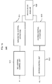
- Figure 15 illustrates an image forming apparatus 1500 including a non-heating control unit 1510 to control non-heating control operations 1511 and a heating control unit 1512 to control heating control operations 1513.
- the non-heating control unit 1510 may be a CPU.
- the power control apparatus of Figure 2 may be included in the image forming apparatus 1500.
- the first warm-up indication signal represents a signal which allows the power supply unit 210 to supply source power to the heating resistor (as roller power) while gradually increasing the maximum level of source power up to a maximum supply level.
- the first warm-up indication signal is generated right after the image forming apparatus is turned on, or right after the image forming apparatus is switched from a stand-by mode to a print mode.
- a control unit hereinafter referred to as a 'heating control unit'
- a control unit hereinafter referred to as a 'non-heating control unit'
- the first warm-up indication signal can be generated by the heating control unit.
- the heating control unit recognizes the heating roller and/or controls heating of the heating roller.
- the heating roller is recognized while initializing the heating control unit, and the initialization time of the heating control unit is adjusted to be negligible.
- the non-heating control unit recognizes a pressure roller, and/or controls driving rotation of the heating roller in conjunction with the pressure roller.
- the non-heating control unit may also control a laser scanning unit (LSU) included in the image forming apparatus.
- LSU laser scanning unit
- the pressure roller is recognized (by the non-heating control unit) while the non-heating control unit is initializing.
- the initialization time of the non-heating control unit is considerably longer than that of the heating control unit.
- the heating control unit may immediately (or nearly immediately) begin to heat the heating roller. For example, the heating control unit begins to heat the heating roller right after completing its initialization requiring negligible initialization time. However, it takes some time, for example, several seconds, to initialize the non-heating control unit. Therefore the heating roller is already in a heated state by the time the initialization of the non-heating control unit is completed.
- the non-heating control unit may be a central processing unit (CPU) of the image forming apparatus.
- the CPU can control necessary operations of the image forming apparatus (to fix the toner image on the printing medium), except for the heating-related operations.
- the control unit of the image forming apparatus of Figure 15 can include the heating control unit and the non-heating control unit.
- the image forming apparatus When the image forming apparatus is turned on, the image forming apparatus can start to perform a heating operation to heat the heating roller before the CPU has been fully initialized.
- Such design is different from a conventional control apparatus of an image forming apparatus where the heating-related operations cannot be started until the CPU is fully initialized.
- the heating control unit and the non-heating control unit may be provided in include hardware and/or software form.
- the second warm-up indication signal represents a signal which allows the power supply unit 210 to supply source power to the heating resistor as roller power while gradually increasing the maximum level of source power up to a maximum supply level.
- the second warm-up signal is generated by the first comparing unit 240.
- the third warm-up signal represents a signal which allows the power supply unit 210 to supply source power of which maximum level is equal to the maximum supply level to the heating resistor as the roller power.
- the third warm-up indication signal is generated by the first comparing unit 240 or the second comparing unit 250.
- the fourth warm-up indication signal represents a signal which allows the toner fixing unit 230 to rotate (or operate) the heating roller in conjunction with the pressure roller.
- the fourth warm-up indication signal is generated by the non-heating controller after the non-heating controller recognizes (or initializes) the pressure roller. In particular, the fourth warm-up indication signal may be generated right after the non-heating controller recognizes the pressure roller.
- the fixing indication signal represents a signal which allows the power supply unit 210 to supply a source power (the maximum level is equal to a thermostat level) to the heating resistor (as the roller power).
- the fixing indication signal can also represent a signal which allows the toner fixing unit 230 to timely feed the printing medium between the heating roller and the pressure roller to allow the toner fixing unit 230 to fix the toner image onto the fed printing medium.
- the fixing indication signal may be generated by the second comparing unit 250, or may be generated by the non-heating control unit (not illustrated) while fixing is performed.
- the first comparing unit 240 compares the maximum level of source power (that is gradually increased) against a predetermined maximum supply level, and generates the second warm-up indication signal or the third warm-up indication signal according to the comparison result obtained by the first comparing unit 240.
- the maximum supply level is the largest maximum level of roller power that can be supplied to the heating resistor.
- the source power is supplied to the heating resistor at the maximum level which is being gradually increased up to the maximum supply level.
- the gradually increasing amounts of source power are supplied to the heating resistor (or to more than one heating resistor, or to more than one selected heating resistors, if multiple heating resistors are provided in the heating roller), for example.
- the first comparing unit 240 if the increased maximum level of the source power supplied is less than the maximum supply level, the first comparing unit 240 generates the second warm-up indication signal. On the other hand, if the maximum level of source power supplied equals the maximum supply level, the first comparing unit 240 generates the third warm-up indication signal.
- the second comparing unit 250 compares a surface temperature (of the heating roller) measured by the temperature measuring unit 220 with a fixing target temperature, (for example, 180 °C) and generates the third warm-up indication signal or the fixing indication signal according to the comparison result obtained by the second comparing unit 250.
- the fixing target temperature represents a surface temperature of the heating roller at which a toner image can be fixed in a stable manner.
- the toner image can be fixed in a stable manner when the surface temperature is a temperature that may be any temperature in the range of a specific minimum fixable temperature and a specific maximum fixable temperature.
- the surface temperature may be the minimum fixable temperature, the maximum fixable temperature or any value in between the minimum and maximum fixable temperatures and still be sufficient to provide fixing of the toner on the printing medium in a stable manner.
- the fixing target temperature is predetermined in the range of the minimum fixable temperature and the maximum fixable temperature. Sufficient source power to stably fix the toner image is provided when the heating roller is at the fixing target temperature (or at or within a suitable range thereof to stably fix the toner image).
- the second comparing unit 250 if the surface temperature measured by the temperature measuring unit 220 is less than the fixing target temperature, the second comparing unit 250 generates the third warm-up indication signal. On the other hand, if the surface temperature measured by the temperature measuring unit 220 equals the fixing target temperature (or is between or at the minimum or maximum fixing temperatures), the second comparing unit 250 generates the fixing indication signal. In addition, the second comparing unit 250 can compare the maximum supply level with a specific maximal rated level, and generate the third warm-up indication signal intermittently based on the comparison result.
- the maximal rated level relates to the maximum level (of rated power) which can be supplied to the heating resistor to heat the heating roller.
- the second comparing unit 250 may calculate the degree to which the maximum supply level exceeds the maximal rated level, and intermittently generate the third warm-up indication signal based on the calculated result. More specifically, referring to Figures 9A and 9B for example, the second comparing unit 250 may calculate a fourth predetermined time K2 which is inversely proportional to the calculated result, and generate the third warm-up indication signal during the fourth predetermined time K2 during every period designated as the third predetermined time K1.
- the fourth predetermined time K2 is equal to or shorter than the third predetermined time K1.
- the fourth predetermined time K2 is determined (or calculated) so that a rate of increase in the surface temperature of the heating roller (being supplied with the source power as roller power having as its upper limit the maximum supply level) is greater when the heating roller is not in contact with the pressure roller (or when the heating roller is not supplying more than a negligible amount of heat to the pressure roller).
- the second comparing unit 250 compares the maximum supply level with the maximal rated level. If the measured surface temperature is determined to be lower than the fixing target temperature, the fourth predetermined time K2 may be increased to intermittently generate the third warm-up indication signal, sufficient to reach the fixing target temperature. However, if the maximum supply level is determined to exceed the maximal rated level, the second comparing unit 250 calculates the fourth predetermined time K2 to be in inverse proportion to the excess value. So, if the maximum supply level exceeds the maximal rated level by a larger (e.g., percentage) amount, then the corresponding fourth predetermined time K2 is reduced. If, on the other hand, the maximum supply level exceeds the maximal rated level by a smaller (e.g., percentage) amount, then the fourth predetermined time K2 is correspondingly increased, for example.
- the examination unit 260 examines whether the image forming apparatus is instructed to print the print data and whether the roller power is being adequately (or sufficiently) supplied (to stably fix the toner image) to the heating resistor normally. If inadequate (or insufficient) roller power is being supplied (to fix the toner image), the examination unit 260 generates the power supply interruption signal in response to such examination result to prevent or interrupt fixing.
- the examination unit 260 may operate in response to the first, second, or third warm-up indication signal and an initializing completion indicating signal.
- the initializing completion indicating signal is a signal representing completion of the initialization of the non-heating control unit (not illustrated).
- the initializing completion indicating signal may be continuously generated by the non-heating control unit (not illustrated), when (and/or after) the initialization of the non-heating control unit is completed.
- the examination unit 260 determines whether the image forming apparatus is not instructed to print the print data or that the roller power (source power supplied to the heating roller or heating resistor) is inadequately (or insufficiently) supplied (i.e., abnormally) to stably fix the toner image
- the examination unit 260 generates the power supply interruption signal.
- Adequately (or sufficiently or normally) supplying the roller power indicates that the roller power is supplied as intended (needed to stably fix the toner image) by the power supply unit 210.
- the power supply unit 210 operates in response to the first, second, or third warm-up indication signal, or the fixing indication signal because no power supply interruption signal has been generated in this case, for example.
- the power supply interruption signal is a signal which allows the power supply unit 210 to interrupt (or to prevent) supplying roller power to the heating resistor.
- the aforementioned power supply unit 210, the temperature measuring unit 220, the first comparing unit 240, and the second comparing unit 250 may operate under the control of the heating control unit (not illustrated), and the toner fixing unit 230, and the examination unit 260 may operate under the control of the non-heating control unit (not illustrated).
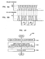
- FIGS 3A and 3B are waveform diagrams illustrating a power control principle to heat a heating roller according to an embodiment of the present general inventive concept.
- some or all of the source voltage (Vin) 300 in the form of a sinusoidal wave is generated by a source voltage generating unit (not illustrated) and is applied to a heating resistor having a variable resistance which increases in proportion to its temperature.
- a roller current (Ir) 320 flows through the heating roller.
- the power supply unit 210 accepts some or all of the source voltage 300 from the source voltage generating unit (not illustrated), and transfers the source voltage 300 to the heating resistor as the roller voltage, as illustrated in Figures 3A and 3B .
- the source voltage 300, the roller voltage, and the roller current 320 have a waveform in the form of alternating current.
- the source power and the roller power also have a waveform in the form of alternating current.
- envelopes of the source power and the roller power have the same positive shape of envelope 332.
- the waveform of the roller current 320 flowing through the heating resistor can be divided into three sections which are a flicker characteristic improving section 310, a maximum power supplying section 312, and a fixing section 314.
- the power supply unit 210 operates in response to the first or second warm-up indication signal and the switching signal.
- the switching signal generator 212, the first synchronizing signal generator 214, the second synchronizing signal generator 216, and the attenuation signal generator 218 are not disposed in the power control apparatus according to an embodiment of the present general inventive concept, in the flicker characteristic improving section 310, the power supply unit 210 operates in response to the first or second warm-up indication signal.
- the power supply unit 210 supplies the source power to the heating resistor as the roller power while gradually increasing the maximum level of the source power up to the maximum supply level. Until the maximum level of the source power reaches the maximum supply level, the roller voltage applied to the heating resistor is a portion of the source voltage 300.
- the resistance of the heating resistor reaches a critical resistance.
- the critical resistance is a resistance of the heating resistor at a time when the resistance does not change although the roller power is continuously provided through the heating resistor.
- the critical resistance may be calculated with the maximum supply level set to the maximal rated level.
- the power supply unit 210 operates in response to the third warm-up indication signal. Specifically, in the maximum power supplying section 312, the power supply unit 210 supplies the source power (the maximum level of which is equal to the maximum supply level) to the heating resistor (as the roller power).
- the source voltage 300 is fully applied to the heating resistor as the roller voltage in the maximum power supplying section 312, as illustrated in Figures 3A and 3B .
- the maximum supply level is the upper limit of the roller power which can be supplied to the heating resistor.
- the maximum supply level may exceed the maximal rated level.
- the maximum supply level may exceed the maximal rated level, may be at the maximal rated level, or may be less then the maximal rated level.
- a rising curve of the surface temperature of the heating roller (being supplied with roller power at the maximum supply level) approximates, or exactly matches the rising curve of the surface temperature of the heating roller being supplied with roller power when the maximum supply level equals the maximal rated level.
- the second comparing unit 250 compares the maximum supply level with the maximal rated level, and calculates a fourth predetermined time K2 which is inversely proportional to how much (i.e., an excess value of) the maximum supply level exceeds the maximal rated level, when the maximum supply level is greater than the maximal rated level.
- the power supply unit 210 supplies source power (at the maximum supply level) to the heating resistor during the fourth predetermined time K2 which occurs during every period designated as the third predetermined time K1, as illustrated in Figures 9A and 9B .
- the power supply unit 210 and the toner fixing unit 230 operate in response to the fixing indication signal. Specifically, in the fixing section 314, the power supply unit 210 supplies the source power (the maximum level of which is now equal to the thermostat level) to the heating resistor (as the roller power), and the toner fixing unit 230 fixes the toner image onto the printing medium by using the heating roller.
- the roller voltage applied to the heating resistor in the fixing section 314 is a portion of the source voltage 300, as illustrated in Figures 3A and 3B .
- the surface temperature of the heating roller above has a first specific similarity with respect to the fixing target temperature.
- the surface temperature may be in the range of 95% ⁇ 105% of the fixing target temperature.
- the surface temperature is between the minimum fixable temperature and the maximum fixable temperature.
- the surface temperature may not fall below the minimum fixable temperature even though the roller power supplied to the heating roller is interrupted (no longer supplied or not supplied) before all the print data is fixed.
- the power supply unit 210 may not supply the source power (the maximum level of which is equal to the thermostat level) to the heating resistor (as the roller power), and yet the toner fixing unit 230 may fix the toner image in a stable manner in the fixing section 314.
- the surface temperature may fall below the minimum fixable temperature if the roller power supplied to the heating roller is interrupted (no longer supplied or not supplied) before all the print data is fixed.
- the power supply unit 210 has to supply the source power (the maximum level of which is equal to the thermostat level) to the heating resistor as the roller power in the fixing section 314.
- the roller power may be supplied to each of heating resistors of the heating roller used during the flicker characteristic improving section 310 and during the maximum power supplying section 312. Whereas, the roller power may be supplied only to selected heating resistors among all the heating resistors of the heating roller during the fixing section 314.
- the heating resistors initially selected to receive source power may be selected by the non-heating control unit (not illustrated), and the heating control unit may then periodically or (non-periodically) change the selected heating resistors that receive source power, for example.
- a time required for the roller current 320 to flow through the initially selected heating resistors includes the time required for the heating resistors themselves to be initially selected by the non-heating control unit (not illustrated).
- the flicker characteristic improving section 310 is described as follows.
- the examination unit 260 examines whether the image forming apparatus is instructed to print the print data and whether the roller power is adequately supplied normally (sufficient to stably fix the print data) during the flicker characteristic improving section 310. In this case, if it is determined that the image forming apparatus is not instructed to print the print data or that the roller power is not adequately supplied (not sufficient to stably fix the print data), then the power supply 210 instructs the heating control unit (not illustrated) not to generate the first warm-up indication signal and instructs the first comparing unit 240 not to generate the second warm-up indication signal.
- the roller power that may be supplied to the heating resistor is interrupted, and the flicker characteristic improving section 310 is also interrupted.
- the roller power supplied to the heating resistors remains uninterrupted and the flicker characteristic improving section 310 proceeds as predetermined.
- the examination unit 260 examines whether the image forming apparatus is instructed to print the print data and whether the roller power is supplied normally during the maximum power supplying section 312.
- the power supply 210 instructs the first comparing unit 240 or the second comparing unit 250 not to generate (or interrupt or stop generating) the third warm-up indication signal. Accordingly, the roller power that may be supplied to the heating resistor is interrupted, and the maximum power supplying section 312 is also interrupted.
- the examination unit 260 determines that the image forming apparatus is instructed to print the print data and that the roller power is adequately supplied normally, then the roller power supplied to the heating resistors remains uninterrupted and the maximum power supplying section 312 proceeds as predetermined.
- FIG. 4 is a flowchart illustrating a power control method to heat a heating roller according to an embodiment of the present general inventive concept.
- the method includes operations (operations 410 to 430) which improve a flicker characteristic and allows the surface temperature of the heating roller to rapidly reach the fixing target temperature. This is achieved by supplying the roller power to the heating resistor differently in the flicker characteristic improving section 310, the maximum power supplying section 312, and the fixing section 314, with respect to one another.
- the power supply unit 210 gradually increases the maximum level of the source power up to a specific maximum supply level, and supplies the source power at the (gradually increasing) maximum level to the heating resistor as the roller power (operation 410).
- Operation 410 may be performed right after the image forming apparatus (connected to the power supply unit) is turned on, or right after the image forming apparatus is switched from the standby mode to the print mode.
- the temperature measuring unit 220 measures the surface temperature of the heating roller, and the power supply unit 210 supplies the source power (the maximum level of which is equal to the maximum supply level) to the heating resistor (as the roller power) until the measured surface temperature (of the heating roller) reaches a specific fixing target temperature (operation 420).
- the power supply unit 210 supplies the source power (the maximum level of which is equal to the thermostat level) to the heating resistor, and the toner fixing unit 230 fixes the toner image of the print data onto the printing medium by using the heating roller and the pressure roller (operation 430).
- the examination unit 260 determines whether the image forming apparatus is instructed to print the print data and whether the roller power is adequately supplied normally.
- the operation 430 is performed, only if it is determined that the image forming apparatus is instructed to print the print data and that the roller power is adequately supplied normally.
- the operations 410 and 420 may be controlled by the heating control unit (not illustrated), and the operation 430 may be controlled by the non-heating control unit (not illustrated).
- the operations 410, 420, and 430 correspond to the flicker characteristic improving section 310, the maximum power supplying section 312, and the fixing section 314, respectively.
- the non-heating control unit determines the time elapsed when print data is no longer being received, and if it is determined that the elapsed time when print data is not being received is equal to or exceeds the standby mode determining time (operation 430 is completed), the image forming apparatus is switched to the standby mode.
- the non-heating control unit also determines when new or additional print data is received after the image forming apparatus is switched to (or is in) the standby mode. If it is determined that the print data (e.g., new or additional print data) is received (or is being received) after the image forming apparatus has been switched to (or is in) the standby mode, then the image forming apparatus is switched to the print mode, and the power supply unit 210 is instructed to execute operations 410 to 430, as needed.
- the print data e.g., new or additional print data
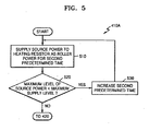
- FIG. 5 is a flowchart illustrating operation 410 of Figure 4 according to an embodiment 410A of the present general inventive concept.
- the maximum level of the source power is gradually increased up to the maximum supply level, and the source power is supplied at the (gradually increased) maximum level to the heating resistor as the roller power.
- the power supply unit 210 supplies the source power to the heating resistor (as the roller power having a first predetermined time interval) for a second predetermined time (operation 510).
- the first predetermined time is a set upper limit of the second predetermined time.
- the first determined time may be invariable.
- the second predetermined time may be variable.
- the first comparing unit 240 determines whether the maximum level of the source power supplied in operation 510 is less than the maximum supply level (operation 520).
- the first comparing unit 240 instructs the power supply unit 210 to increase the second predetermined time and to allow the power supply unit 210 to repeat operation 510 (operation 530).
- operation 420 is completed.
- the second predetermined time is gradually increased so that the maximum level of the source power supplied approaches and eventually equals (or approximately equals) the maximum supply level. Accordingly, the degree or occurrence of the flicker characteristic is reduced (or becomes less pronounced), which may occur (for example) when the roller power is rapidly (and/or excessively) supplied to the heating resistor at a point where the image forming apparatus is turned on or where the image forming apparatus is switched from the standby mode to the print mode.
- Figures 6A, 6B, 6C, 6D and 6E include waveforms corresponding to certain operations of the flowchart illustrated in Figure 5 , when the switching signal generator 212 through the attenuation signal generator 218 are part of the power control apparatus according to one or more embodiments of the present general inventive concept.
- Figure 6A illustrates the source voltage (Vin) 300 illustrated in Figure 3A .
- Figure 6B illustrates a first synchronizing signal (S1) 610.
- Figure 6C illustrates a second synchronizing signal (S2) 620 and an attenuation signal (A1) 630.
- Figure 6D illustrates the switching signal (S3) 640.
- Figure 6E illustrates the roller voltage (Vin') 650.
- the roller voltage (Vin') 650 in the flicker characteristic improving section 310 is the source voltage (Vin) 300 corresponding to the non-zero signal section Q2 of the switching signal (S3) 640.
- Q1 is the first predetermined time
- Q2 is the second predetermined time. That is, Q2 is the time width of the non-zero signal section of the switching signal S3.
- the second predetermined time Q2 gradually increases up to (and/or including) Q1.
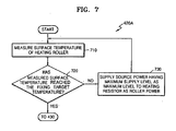
- FIG. 7 is a flowchart illustrating operation 420 of Figure 4 according to an embodiment 420A of the present general inventive concept.
- the surface temperature of the heating roller is measured, and the source power (the maximum level of which is equal to the maximum supply level) is supplied at the maximum level to the heating resistor (as the roller power) until the measured surface temperature reaches the fixing target temperature.
- the temperature measuring unit 220 measures the surface temperature of the heating roller (operation 710).
- the second comparing unit 250 determines whether the surface temperature measured in operation 710 is equal to the fixing target temperature (operation 720). In other words, in operation 720, it is determined whether the measured surface temperature has reached the fixing target temperature.
- the power supply unit 210 continues to supply the source power (the maximum level of which is equal to the maximum supply level) at the maximum level to the heating resistor as the roller power (operation 730).
- operation 420 is completed.
- Figure 8 is a flowchart of operation 420 illustrated in Figure 4 according to another embodiment 420B of the present general inventive concept.
- the operation 420 includes sub-operations 810, 820, 830, and 840 in which the source power (having the maximum supply level as an upper limit) is supplied to the heating resistor at the maximum supply level during a period corresponding to how much (i.e., an excess value of) the maximum supply level that exceeds the maximal rated level until the surface temperature of the heating roller reaches the fixing target temperature.
- the temperature measuring unit 220 measures the surface temperature of the heating roller (operation 810).
- the second comparing unit 250 determines whether the measured surface temperature in the operation 810 is the same as the fixing target temperature (operation 820).
- the second comparing unit 250 calculates a fourth predetermined time K2 which is inversely proportional to an excess value of the maximum supply level that exceeds the maximal rated level (operation 830).
- the calculated fourth predetermined time K2 is inversely proportional to the amount of the maximum supply level that exceeds the maximal rated level.
- the maximum supply level exceeds the maximal rated level by say 10%
- the next corresponding calculated fourth predetermined time K2 is correspondingly shorter (or smaller) as the maximum supply level that exceeds the maximal rated level is increased over 10%, e.g., by more than 11%, by more than 12%, by more than 13%, by more than 20%, etc.
- the power supply unit 210 supplies source power (having the maximum supply level as a maximum level) to the heating resistor during the fourth predetermined time K2 during every period designated as the third predetermined time K1 (operation 840), as further illustrated in Figure 9B .
- the measured surface temperature is the same as the fixing target temperature in operation 820 then operation 420 is completed and the next operation is operation 430 illustrated in Figure 4 .
- Figures 9A and 9B are diagrams of waveforms corresponding to operation 840 illustrated in Figure 8 .
- a maximum level (equal to the maximum supply level) of the roller power is being supplied to the heating resistor in the maximum power supplying section 312.
- the maximum supply level Mp may exceed the maximal rated level Ms by (Mp-Ms). So, as noted above, K2 decreases as (Mp - Ms) increases.
- the surface temperature of the heating roller has a high probability of overshooting the fixing target temperature. If the roller power is supplied so that Mp ⁇ Ms, the surface temperature of the heating roller has a high probability of undershooting the fixing target temperature. Excessive overshooting and undershooting cause problems such as decrease in fixedness and shortening of a life cycle of the heating resistor. So the overshooting and undershooting problems should be prevented from occurring or should occur less frequently to provide improved fixedness and/or improved life cycle of the heating resistor.
- the source power is supplied at the maximum supply level to the heating resistor (as the roller power) during the fourth predetermined time K2 of every third predetermined time K1, as illustrated in Figure 9B .
- FIG 10 is a flowchart illustrating operation 430 of Figure 4 according to an embodiment 430A of the present general inventive concept.
- the source power (the maximum level of which is equal to the thermostat level) is supplied to the heating resistor (as the roller power) to fix the toner image.
- the non-heating control unit (not illustrated) selects one or more heating resistors among a plurality of heating resistors (e.g., less than all or all) included in the heating roller (operation 1010).
- the power supply unit 210 supplies the source power (the maximum level of which is equal to the thermostat level) to the heating resistor selected in operation 1010 as the roller power (operation 1020).
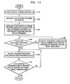
- FIG. 11 is a detailed flowchart illustrating a process of heating the surface of a pressure roller up to a fixing target temperature before operation 430 of Figure 4 is executed, according to an embodiment of the present general inventive concept.
- the process of heating the surface of the pressure roller includes operations 1110 through 1170 to heat the surface of the pressure roller while operation 420 of Figure 4 is being completed right after the non-heating controller of the image forming apparatus recognizes the pressure roller.
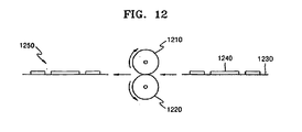
- Figure 12 is a reference diagram corresponding to certain operations of the process of Figure 11 .
- Figures 13A and 13B are plots of surface temperature versus time corresponding to or used to explain certain operations of the process of Figure 11 .
- Figure 13A illustrates a timing graph 1310 of the surface temperature of the heating roller according to the conventional power control principle.
- Figure 13B illustrates a timing graph 1320 of the surface temperature of the heating roller according to the power control principle of an embodiment of the present general inventive concept.
- the process of Figure 11 will now be described in detail with reference to Figures 12 , 13A and 13B .
- both the surface temperature of the heating roller 1210 and the surface temperature of the pressure roller 1220 should be the same as the fixing target temperature ST t or approximately at ST t sufficient to accomplish stable fixing. That is, before operation 430 of Figure 4 is executed, both the surface temperature of the heating roller 1210 and the surface temperature of the pressure roller 1220 must (or should) reach the fixing target temperature ST t .
- the pressure roller 1220 To increase the surface temperature of the pressure roller 1220, the pressure roller 1220 must accept the heat from the heating roller 1210 while operating in conjunction with the heating roller 1210 because the pressure roller 1220 does not have any of its own heating resistors unlike the heating roller 1210, for example. Considering this exemplary configuration, the variation of the surface temperature of the heating roller 1210 in the flicker characteristic improving section 310 and the maximum power supplying section 312 will now be described.
- both the heating related job and the non-heating related job are controlled by the same controller (not illustrated).
- the controller may be a CPU of the image forming apparatus.
- the surface temperature of the heating roller 1210 cannot increase as quickly when the pressure roller 1220 operates in conjunction with heating roller 1210 because the pressure roller 1220 absorbs heat from the heating roller 1210.
- the heating controller (not illustrated) immediately recognizes the heating roller 1210 and immediately instructs the power supply unit 210 to begin to supply source power to the heating resistor.
- the duration corresponding to T3 described above is eliminated from the FPOT.
- FPOT can be reduced by the duration T3 (from that of a conventional power control principle) when using an embodiment of the present general inventive concept.
- operations 1110 through 1170 are performed before operation 430 of FIG 4 is executed as further described below.
- the non-heating controller is initialized.
- the pressure roller 1220 operates in conjunction with the heating roller 1210 as soon as the pressure roller 1220 is recognized by the non-heating controller.
- the non-heating controller recognizes at least one (one or more) of the components (of the image forming apparatus).
- the non-heating controller determines whether the pressure roller 1220 has been recognized by the CPU.
- operation 1140 If it is determined (in operation 1140) that the pressure roller 1220 has not been recognized by the CPU, then operation 1150 is executed, where the non-heating controller recognizes at least one of any other remaining unrecognized components, and proceeds back to the operation 1140.
- the toner fixing unit 230 operates the pressure roller 1220 in conjunction with the heating roller 1210 in operation 1160, and the second comparing unit 250 determines in operation 1170 whether the surface temperature of the heating roller 1210 has reached the fixing target temperature ST t .
- operation 1170 If (in operation 1170) it is determined that the surface temperature of the heating roller 1210 has not reached the fixing target temperature ST t , then the process is directed back to operation 1160 which is repeated followed by operation 1170 according to the flowchart of Figure 11 , for example. If (in operation 1170) it is determined that the surface temperature of the heating roller 1210 has reached the fixing target temperature ST t , then operation 420 of Figure 4 is completed. Then the process proceeds to operation 430 of Figure 4 .
- Figure 14 illustrates control data that may be stored in a heating control unit (not illustrated) and a non-heating control unit (not illustrated) according to one or more embodiments of the present general inventive concept.
- the heating control unit (not illustrated) and the non-heating control unit (not illustrated) may include predetermined storage units therein, respectively.
- the storage unit may be embodied as a RAM.
- the storage unit included in the heating control unit (not illustrated) is referred to as a first storage unit.
- the storage unit included in the non-heating control unit (not illustrated) is referred to as a second storage unit.
- the heating control unit (not illustrated) can receive/transmit control data 1410 to/from the non-heating control unit (not illustrated).
- control data 1410 may include power supply interruption information 1420 to indicate that the supply of the roller power is interrupted (IH_OFF), fixing target temperature information 1430 to indicate the fixing target temperature (TH_REF), error indicating information 1440 to indicate that the roller power is inadequately (or insufficiently) supplied (i.e., abnormally) (SYS_ERROR) necessary to stably fix the toner image, and measured surface temperature information 1450 to indicate the measured surface temperature of the heating roller (TEMP).
- power supply interruption information 1420 to indicate that the supply of the roller power is interrupted
- fixing target temperature information 1430 to indicate the fixing target temperature (TH_REF)
- error indicating information 1440 to indicate that the roller power is inadequately (or insufficiently) supplied (i.e., abnormally)
- measured surface temperature information 1450 to indicate the measured surface temperature of the heating roller (TEMP).
- zeroth, first, second, and third addresses ADD 0, ADD 1, ADD 2, and ADD 3 indicate addresses for storing the power supply interruption information 1420, the fixing target temperature information 1430, the error indicating information 1440, and the measured surface temperature information 1450, respectively.
- the operations of the power supply unit 210, the temperature measuring unit 220, the first comparing unit 240, and the second comparing unit 250 are controlled by the heating control unit (not illustrated), then the control data 1410 stored in the first storage unit (not illustrated) is updated according to the operating result whenever each of the aforementioned elements 210, 220, 240 and 250 perform an appropriate operation.
- the heating control unit (not illustrated) can transmit the updated control data 1410 to the non-heating control unit (not illustrated), and the non-heating control unit (not illustrated) can update the control data 1410 stored in the second storage unit (not illustrated).
- the control data 1410 stored in the first storage unit (not illustrated) is updated according to the operating result whenever each of the aforementioned elements 230 and 260 perform an appropriate operation.
- the non-heating control unit (not illustrated) can transmit the updated control data 1410 to the non-heating control unit (not illustrated), and the non-heating control unit (not illustrated) can update the control data 1410 stored in the second storage unit (not illustrate).
- the aforementioned power supply interruption signal may be defined as a signal including the power supply interruption information 1420 and the error indicating information 1440.
- a heating roller when the image forming apparatus is turned on, a heating roller can be heated before the rest of the image forming apparatus is fully initialized, power can be supplied to the heating roller in such a way that the power is gradually increased at an early stage and a maximum power is supplied after a specific time elapses.
- the flicker characteristic can be improved, and a surface temperature of the heating roller can rapidly reach a fixing target temperature.
- the surface temperature of the heating roller can reach the fixing target temperature quickly without overshooting or undershooting even when the maximum supply level exceeds the maximal rated level.
- One or more embodiments of the general inventive concept can also be provided as computer readable codes as a program on a computer readable recording medium.
- the computer readable recording medium is any data storage device that can store data which can be thereafter read by a computer system. Examples of the computer readable recording medium include read-only memory (ROM), random-access memory (RAM), CD-ROMs, magnetic tapes, floppy disks, optical data storage devices, and carrier waves (such as data transmission through the Internet).
- the computer readable recording medium can also be distributed over network coupled computer systems so that the computer readable code is stored and executed in a distributed fashion.
Landscapes
- Physics & Mathematics (AREA)
- General Physics & Mathematics (AREA)
- Fixing For Electrophotography (AREA)
- Control Or Security For Electrophotography (AREA)
Claims (27)
- Leistungssteuerungsverfahren zum Erhitzen einer Heizwalze (1210), die bereitgestellt wird, um ein Tonerbild (1240) in einer Bilderzeugungsvorrichtung zu fixieren, wobei die Heizwalze (1210) einen Heizwiderstand aufweist, das Leistungssteuerungsverfahren umfassend:graduelles Erhöhen von Leistung, die dem Heizwiderstand zugeführt wird, bis zu einem im Voraus bestimmten maximalen Zuführungspegel (MP);Messen einer Oberflächentemperatur der Heizwalze (1210) und weiterhin Zuführen der Leistung bei dem maximalen Zuführungspegel (MP) zu dem Heizwiderstand, bis die gemessene Oberflächentemperatur eine spezifische Fixierungs-Zieltemperatur erreicht;dadurch gekennzeichnet, dassdie weitere Zuführung der Quellenleistung umfasst, die Quellenleistung intermittierend korrespondierend mit einem Überschusswert des maximalen Zuführungspegels (MP) , der einen spezifizierten maximalen Nennpegel (MS) übersteigt, zuzuführen.
- Leistungssteuerungsverfahren nach Anspruch 1, wobei das Zuführen der Leistung umfasst, das Zuführen der Leistung im Wesentlichen unmittelbar nach dem Einschalten der Bilderzeugungsvorrichtung oder im Wesentlichen unmittelbar nach dem Umschalten der Bilderzeugungsvorrichtung von einem Bereitschaftsmodus in einen Druckmodus zu starten.
- Leistungssteuerungsverfahren nach einem der vorstehenden Ansprüche, wobei das Zuführen der Leistung umfasst, die Leistung zu dem Heizwiderstand während einer zweiten, im Voraus bestimmten Zeit (Q2) zu jeder ersten, im Voraus bestimmten Zeit (Q1) zuzuführen, und wobei die zweite, im Voraus bestimmte Zeit bis zu der ersten, im Voraus bestimmten Zeit verlängert wird, während der Leistungspegel sich dem maximalen Zuführungspegel annähert.
- Leistungssteuerungsverfahren nach einem der vorstehenden Ansprüche, wobei der maximale Zuführungspegel eine obere Begrenzung des Leistungspegels ist, der dem Heizwiderstand zugeführt wird.
- Leistungssteuerungsverfahren nach einem der vorstehenden Ansprüche, umfassend:Zuführen, zu der Heizwalze (1210), eines Leistungspegels, der auf einen Thermostatpegel angepasst ist, der niedriger als der maximale Zuführungspegel ist, während des Fixierens des Tonerbilds; wobeidie Oberflächentemperatur der Heizwalze (1210) die Fixierungs-Zieltemperatur erreicht hat, wenn die zugeführte Leistung an dem Thermostatpegel liegt.
- Leistungssteuerungsverfahren nach Anspruch 5, wobei:das Fixieren des Tonerbilds (1240) umfasst:Auswählen mindestens eines Heizwiderstands aus einer Vielzahl von Heizwiderständen; undZuführen der Quellenleistung nur zu jedem der ausgewählten Heizwiderstände, um das Tonerbild zu fixieren.
- Leistungssteuerungsverfahren nach einem der vorstehenden Ansprüche, weiter umfassend:Umschalten der Bilderzeugungsvorrichtung in einen Bereitschaftsmodus, wenn bestimmt wird, dass neue oder zusätzliche Druckdaten nicht empfangen werden, wenn eine Bereitschaftsmodus-Bestimmungszeit verstrichen ist; undUmschalten der Bilderzeugungsvorrichtung in einen Druckmodus, wenn neue oder zusätzliche Druckdaten empfangen werden.
- Leistungssteuerungsverfahren nach einem der vorstehenden Ansprüche, wobei der Heizwiderstand einen variablen Widerstand proportional zu einer Temperatur des Heizwiderstands aufweist, die kleiner als eine oder gleich einer Schwellentemperatur ist.
- Leistungssteuerungsverfahren nach einem der vorstehenden Ansprüche, wobei:die Bilderzeugungsvorrichtung die Heizwalze (1210) und eine Druckwalze (1220) enthält,das Tonerbild unter Verwendung der Heizwalze (1210) und der Druckwalze fixiert wird und wobei das Leistungssteuerungsverfahren weiter umfasst, die Druckwalze in Verbindung mit der Heizwalze zu betreiben, bis die gemessene Oberflächentemperatur die spezifische Fixierungstemperatur vor dem Fixieren des Tonerbilds erreicht.
- Leistungssteuerungsverfahren nach Anspruch 1, wobei das weitere Zuführen der Quellenleistung umfasst, die Quellenleistung zu dem Heizwiderstand zuzuführen, die während einer vierten, im Voraus bestimmten Zeit geleitet wird, die während einer dritten, im Voraus bestimmten Zeit wiederholt wird, und wobei die vierte, im Voraus bestimmte Zeit umgekehrt proportional zu dem Überschusswert ist.
- Leistungssteuerungsverfahren nach Anspruch 1 oder 10, wobei der maximale Nennpegel zu einer oberen Begrenzung der Nennleistung, die dem Heizwiderstand zugeführt werden kann, in Beziehung steht.
- Leistungssteuerungsverfahren nach Anspruch 1, weiter umfassend:Bestimmen, ob die Bilderzeugungsvorrichtung angewiesen ist, Druckdaten korrespondierend mit dem Tonerbild (1240) zu drucken, und Bestimmen, ob dem Heizwiderstand ausreichend Leistung zugeführt wird, um das Tonerbild zu fixieren; undFixieren des Tonerbilds (1240) auf ein Druckmedium, wenn bestimmt wird, dass die Bilderzeugungsvorrichtung angewiesen ist, die Druckdaten zu drucken, und die ausreichende Leistung zugeführt wird.
- Leistungssteuerungsverfahren nach Anspruch 12, weiter umfassend:Unterbrechen der Leistungszuführung, wenn bestimmt wird, dass die Bilderzeugungsvorrichtung nicht angewiesen ist, die Druckdaten zu drucken, oder dass keine ausreichende Leistung zugeführt wird.
- Leistungssteuerungsvorrichtung zum Erhitzen einer Heizwalze (1210), die bereitgestellt wird, um ein Tonerbild (1240) von Druckdaten in einer Bilderzeugungsvorrichtung zu fixieren, wobei die Heizwalze (1210) einen Heizwiderstand aufweist, um Leistung zu empfangen, die Leistungssteuerungsvorrichtung umfassend:eine Leistungszuführungseinheit (210) zum graduellen Erhöhen eines maximalen Pegels von Quellenleistung, die von einer externen Quelle zugeführt wird, bis zu einem spezifischen maximalen Zuführungspegel als Reaktion auf ein erstes oder ein zweites Aufwärmungs-Anzeigesignal, zum Ausgeben der Quellenleistung bei dem maximalen Pegel zu dem Heizwiderstand als Reaktion auf das erste oder zweite Aufwärmungs-Anzeigesignal, zum Ausgeben der Quellenleistung bei dem maximalen Zuführungspegel zu dem Heizwiderstand als Reaktion auf ein drittes Aufwärmungs-Anzeigesignal und zum Ausgeben der Quellenleistung bei einem Pegel, der angepasst ist, um einen Thermostatpegel nicht zu übersteigen, zu dem Heizwiderstand als Reaktion auf ein Fixierungs-Anzeigesignal;eine Temperaturmesseinheit (220) zum Messen einer Oberflächentemperatur der Heizwalze als Reaktion auf das dritte Aufwärmungs-Anzeigesignal und zum Ausgeben der gemessenen Oberflächentemperatur;eine Tonerfixierungseinheit (230) zum Fixieren des Tonerbilds von Druckdaten auf ein zugeführtes Druckmedium unter Verwendung der Heizwalze als Reaktion auf das Fixierungs-Anzeigesignal;eine erste Vergleichseinheit (240) zum Vergleichen des erhöhten maximalen Pegels mit dem maximalen Zuführungspegel und zum Erzeugen des zweiten oder dritten Aufwärmungs-Anzeigesignals gemäß einem ersten Vergleichsergebnis; undeine zweite Vergleichseinheit (250) zum Vergleichen der gemessenen Oberflächentemperatur mit einer spezifischen Fixierungs-Zieltemperatur und zum Erzeugen des dritten Aufwärmungs-Anzeigesignals oder des Fixierungs-Anzeigesignals gemäß einem zweiten Vergleichsergebnis;wobei die zweite Vergleichseinheit auch bereitgestellt wird, den maximalen Zuführungspegel (MP) mit einem spezifischen maximalen Nennpegel (MS) zu vergleichen und das dritte Aufwärmungs-Anzeigesignal intermittierend gemäß dem Vergleichsergebnis zu erzeugen.
- Leistungssteuerungsvorrichtung nach Anspruch 14, wobei das erste Aufwärmungs-Anzeigesignal sofort nach dem Einschalten der Bilderzeugungsvorrichtung oder sofort nach dem Umschalten der Bilderzeugungsvorrichtung von einem Bereitschaftsmodus in einen Druckmodus erzeugt wird.
- Leistungssteuerungsvorrichtung nach Anspruch 14 oder 15, wobei die Bilderzeugungsvorrichtung (1500) eine Einheit (1512) zur Steuerung von Operationen, die zum Erhitzen in Beziehung stehen, einschließlich von Operationen der Leistungszuführungseinheit, und eine andere Einheit (1510) zur Steuerung von Operationen, die nicht zum Erhitzen in Beziehen stehen, einschließlich von Operationen der Tonerfixierungseinheit, umfasst und die Einheit und die andere Einheit (1510) getrennt in der Bilderzeugungsvorrichtung bereitgestellt werden.
- Leistungssteuerungsvorrichtung nach Anspruch 14, 15 oder 16, wobei die Leistungszuführungseinheit (210) die Quellenleistung zu dem Heizwiderstand während einer zweiten, im Voraus bestimmten Zeit (Q2) zu jeder ersten, im Voraus bestimmten Zeit (Q1) als Reaktion auf das erste oder zweite Aufwärmungs-Anzeigesignal ausgibt und wobei die zweite, im Voraus bestimmte Zeit bis zu der ersten, im Voraus bestimmten Zeit verlängert wird, während der maximale Pegel der Quellenleistung sich dem maximalen Zuführungspegel annähert.
- Leistungssteuerungsvorrichtung nach einem der Ansprüche 14 bis 17, wobei der maximale Zuführungspegel eine obere Begrenzung des Leistungspegels ist, der dem Heizwiderstand zugeführt wird.
- Leistungssteuerungsvorrichtung nach einem der Ansprüche 14 bis 18, wobei das Fixierungs-Anzeigesignal gemäß dem zweiten Vergleichsergebnis erzeugt wird, das von der zweiten Vergleichseinheit (250) ermittelt wird, und erzeugt wird, während die Tonerfixierungseinheit in Betrieb ist.
- Leistungssteuerungsvorrichtung nach einem der Ansprüche 14 bis 19, wobei der Heizwiderstand einen variablen Widerstand proportional zu einer Temperatur des Heizwiderstands aufweist, die kleiner als eine oder gleich einer Schwellentemperatur ist.
- Leistungssteuerungsvorrichtung nach einem der Ansprüche 14 bis 20, wobei die Leistungszuführungseinheit (210) die Quellenleistung zu dem Heizwiderstand als Reaktion auf ein Umschaltungssignal und einem des ersten und zweiten Aufwärmungs-Anzeigesignals ausgibt, während sie den Pegel der Quellenleistung graduell erhöht, und wobei das Umschaltungssignal als Reaktion auf das erste oder zweite Aufwärmungs-Anzeigesignal erzeugt wird.
- Leistungssteuerungsvorrichtung nach einem der Ansprüche 14 bis 21, weiter umfassend:einen ersten Synchronisierungssignalgenerator (214) zum Erzeugen eines ersten Synchronisierungssignals mit einer rechtwinkligen Wellenform, das als Reaktion auf das erste oder zweite Aufwärmungs-Anzeigesignal mit der Quellenleistung synchronisiert wird;einen zweiten Synchronisierungssignalgenerator (216) zum Integrieren des ersten Synchronisierungssignals und zum Ausgeben eines Integrationsergebnisses als ein zweites Synchronisierungssignal;einen Dämpfungssignalgenerator (218) zum Erzeugen eines Dämpfungssignals zum Dämpfen des zweiten Synchronisierungssignals an einer im Voraus bestimmten Flanke als Reaktion auf das erste oder zweite Aufwärmungs-Anzeigesignal; undeinen Umschaltungssignalgenerator (212) zum Erzeugen eines Umschaltungssignals mit einem rechtwinkligen Wellenformsignalabschnitt ungleich null, wenn das Dämpfungssignal gleich dem oder kleiner als das zweite Synchronisierungssignal ist,wobei die Leistungszuführung (210) die Quellenleistung zu den Heizwiderständen bei einem Signalabschnitt ungleich null des Umschaltungssignals als Reaktion auf das erste oder zweite Aufwärmungs-Anzeigesignal ausgibt, undwobei das Dämpfungssignal zu einem Nullsignal reduziert wird, bevor das dritte Anzeigesignal erzeugt wird.
- Leistungssteuerungsvorrichtung nach einem der Ansprüche 14 bis 22, wobei die Bilderzeugungsvorrichtung die Heizwalze und eine Druckwalze enthält, die Druckwalze in Verbindung mit der Heizwalze als Bestandteil der Tonerfixierungseinheit als Reaktion auf ein viertes Aufwärmungs-Anzeigesignal betrieben wird,
wobei das Tonerbild (1240) auf das Druckmedium unter Verwendung der Heizwalze und der Druckwalze der Tonerfixierungseinheit fixiert wird, um als Reaktion auf das Fixierungs-Anzeigesignal zu operieren, und
wobei das vierte Aufwärmungs-Anzeigesignal sofort erzeugt wird, nachdem die Bilderzeugungsvorrichtung die Druckwalze erkennt. - Leistungssteuerungsvorrichtung nach Anspruch 14, wobei der maximale Nennpegel zu einer oberen Begrenzung der Nennleistung, die dem Heizwiderstand zugeführt werden kann, in Beziehung steht.
- Leistungssteuerungsvorrichtung nach einem der Ansprüche 14 bis 24, weiter umfassend:eine Untersuchungseinheit (260) zum Untersuchen, ob die Bilderzeugungsvorrichtung angewiesen ist, die Druckdaten zu drucken, und zum Untersuchen, ob die zugeführte Leistung ausreichend ist, um die Druckdaten zu fixieren, und zum Erzeugen eines Leistungszuführungs-Unterbrechungssignals als Reaktion auf das Untersuchungsergebnis,wobei die Leistungszuführungseinheit (210) als Reaktion auf das Leistungszuführungs-Unterbrechungssignal keine Leistung zu dem Heizwiderstand ausgibt.
- Bilderzeugungsvorrichtung mit einer Heizwalze, die bereitgestellt wird, um ein Tonerbild zu fixieren, wobei die Heizwalze (1210) einen Heizwiderstand zum Empfangen von Leistung aufweist, die Bilderzeugungsvorrichtung eine Leistungssteuerungsvorrichtung nach einem der Ansprüche 14 bis 25 umfassend.
- Computerprogramm, das, wenn es von einem Prozessor ausgeführt wird, angeordnet ist, um das Verfahren nach einem der Ansprüche 1 bis 13 auszuführen.
Applications Claiming Priority (5)
| Application Number | Priority Date | Filing Date | Title |
|---|---|---|---|
| KR1020060007255A KR100677631B1 (ko) | 2006-01-24 | 2006-01-24 | 정착 가열 롤러를 위한 전력 제어 방법 및 장치 |
| KR1020060011778A KR100788679B1 (ko) | 2006-02-07 | 2006-02-07 | 정착 가열 롤러를 위한 전력 제어 방법 및 장치 |
| KR1020060012886A KR100754206B1 (ko) | 2006-02-10 | 2006-02-10 | 가열 롤러를 위한 전력 제어 방법 및 장치 |
| KR1020060018427A KR100788680B1 (ko) | 2006-02-24 | 2006-02-24 | 가열 롤러를 위한 전력 제어 방법과 장치 및 그 방법을 컴퓨터에서 실행시키기 위한 컴퓨터 프로그램을 저장한 컴퓨터로 읽을 수 있는 기록매체 |
| KR1020060023567A KR100846784B1 (ko) | 2006-03-14 | 2006-03-14 | 가열 롤러를 위한 전력 제어 방법 및 장치 |
Publications (2)
| Publication Number | Publication Date |
|---|---|
| EP1811345A1 EP1811345A1 (de) | 2007-07-25 |
| EP1811345B1 true EP1811345B1 (de) | 2010-07-21 |
Family
ID=37963805
Family Applications (1)
| Application Number | Title | Priority Date | Filing Date |
|---|---|---|---|
| EP07101095A Ceased EP1811345B1 (de) | 2006-01-24 | 2007-01-24 | Leistungsregelung für eine Heizwalze in einem Bildformungsapparat |
Country Status (4)
| Country | Link |
|---|---|
| US (5) | US7826759B2 (de) |
| EP (1) | EP1811345B1 (de) |
| JP (2) | JP2007199719A (de) |
| DE (1) | DE602007007828D1 (de) |
Families Citing this family (11)
| Publication number | Priority date | Publication date | Assignee | Title |
|---|---|---|---|---|
| EP1863380B1 (de) | 2005-03-01 | 2019-10-02 | Masimo Laboratories, Inc. | Mehrwellenlängen-sensoranbringung |
| US7826759B2 (en) * | 2006-01-24 | 2010-11-02 | Samsung Electronics Co., Ltd. | Power control method and apparatus to heat a heating roller |
| KR100846785B1 (ko) | 2006-03-14 | 2008-07-16 | 삼성전자주식회사 | 가열 롤러를 위한 전력 제어 방법과 장치 및 이를 위한위상 제어 회로 |
| JP5424012B2 (ja) * | 2008-08-27 | 2014-02-26 | 株式会社リコー | 定着装置の制御方法、定着装置及び画像形成装置 |
| KR101217634B1 (ko) * | 2008-10-01 | 2013-01-02 | 삼성전자주식회사 | 화상형성장치 및 이를 위한 제어방법 |
| JP2010191217A (ja) * | 2009-02-18 | 2010-09-02 | Sharp Corp | 定着装置、画像形成装置、該定着装置を実現するための制御プログラム、および該制御プログラムを記録した記録媒体、ならびに定着装置の制御方法 |
| US9839381B1 (en) | 2009-11-24 | 2017-12-12 | Cercacor Laboratories, Inc. | Physiological measurement system with automatic wavelength adjustment |
| US8639145B2 (en) * | 2010-11-03 | 2014-01-28 | Kabushiki Kaisha Toshiba | Image forming apparatus and method |
| KR101873033B1 (ko) * | 2011-12-01 | 2018-07-03 | 에이치피프린팅코리아 주식회사 | 전압 공용화 화상 형성 장치 및 이의 정착 온도 제어 방법 |
| WO2020046393A1 (en) * | 2018-08-31 | 2020-03-05 | Hewlett-Packard Development Company, L.P. | Reduce zero power events of a heated system |
| JP2023155574A (ja) * | 2022-04-11 | 2023-10-23 | 京セラドキュメントソリューションズ株式会社 | 定着装置、画像形成装置、給電制御方法 |
Family Cites Families (47)
| Publication number | Priority date | Publication date | Assignee | Title |
|---|---|---|---|---|
| JPS56142563A (en) * | 1980-04-07 | 1981-11-06 | Canon Inc | Fixing device |
| CA1281365C (en) * | 1985-08-20 | 1991-03-12 | Masato Kawashima | Printing apparatus |
| JPH05224559A (ja) * | 1991-12-10 | 1993-09-03 | Nec Corp | 電子写真式プリンタにおける定着温度制御装置 |
| JPH05297760A (ja) | 1992-04-22 | 1993-11-12 | Seiko Epson Corp | 定着装置 |
| JPH06348163A (ja) * | 1993-06-04 | 1994-12-22 | Canon Inc | 加熱定着装置及びプリンター並びに弾性回転体の表面電位制御手段 |
| GB2321319B (en) | 1993-10-15 | 1998-09-02 | Seiko Epson Corp | Temperature control in a fixing device for an image forming apparatus |
| JP3121975B2 (ja) * | 1993-12-22 | 2001-01-09 | キヤノン株式会社 | 定着装置 |
| JPH08248816A (ja) | 1995-01-09 | 1996-09-27 | Fujitsu Ltd | 画像記録装置及びその制御方法及び温度制御装置 |
| JP3400596B2 (ja) * | 1995-03-24 | 2003-04-28 | 株式会社リコー | 熱定着装置 |
| JP3454988B2 (ja) | 1995-10-13 | 2003-10-06 | 株式会社リコー | ヒータ制御装置 |
| US6006051A (en) * | 1995-10-19 | 1999-12-21 | Ricoh Company, Ltd. | Electrophotographic apparatus and image forming apparatus employed therein with controlled timing of a power supply |
| JPH09120230A (ja) * | 1995-10-25 | 1997-05-06 | Minolta Co Ltd | 定着装置 |
| US6239411B1 (en) * | 1995-10-27 | 2001-05-29 | Minolta Co., Ltd. | Fixing device |
| EP0797130B1 (de) * | 1996-03-21 | 2001-10-10 | Canon Kabushiki Kaisha | Heizgerät für ein Bild |
| JPH1010914A (ja) | 1996-06-19 | 1998-01-16 | Ricoh Co Ltd | 電子写真装置 |
| JPH10254274A (ja) * | 1997-03-13 | 1998-09-25 | Fujitsu Ltd | 定着装置及び画像形成装置 |
| JP3486319B2 (ja) | 1997-05-01 | 2004-01-13 | 株式会社リコー | 定着ヒータ制御装置 |
| JPH11272113A (ja) | 1998-01-19 | 1999-10-08 | Ricoh Co Ltd | 画像形成装置 |
| JPH11233235A (ja) | 1998-02-16 | 1999-08-27 | Fuji Xerox Co Ltd | 加熱制御方法、ヒータ及び定着装置 |
| JP2002050450A (ja) | 2000-08-04 | 2002-02-15 | Canon Inc | ヒータ制御方法および画像形成装置 |
| JP2002063981A (ja) | 2000-08-18 | 2002-02-28 | Hitachi Koki Co Ltd | ヒータドライバ |
| JP2002214960A (ja) * | 2001-01-15 | 2002-07-31 | Canon Inc | 画像形成装置 |
| KR100385989B1 (ko) | 2001-01-30 | 2003-06-02 | 삼성전자주식회사 | 직접 가열 롤러를 위한 전력 제어 방법 및 장치 |
| KR200263663Y1 (ko) | 2001-05-07 | 2002-02-08 | 이용만 | 구명용 지팡이 |
| KR100389872B1 (ko) | 2001-11-12 | 2003-07-04 | 삼성전자주식회사 | 전자사진 형성장치의 정착롤러를 위한 전력 제어 방법 및장치 |
| JP2003332039A (ja) | 2002-03-04 | 2003-11-21 | Sharp Corp | 高周波加熱装置 |
| JP2004078146A (ja) * | 2002-03-14 | 2004-03-11 | Ricoh Co Ltd | 画像形成装置およびヒータ制御方法 |
| JP4100975B2 (ja) * | 2002-06-13 | 2008-06-11 | キヤノン株式会社 | 加熱装置及び画像形成装置 |
| JP4343515B2 (ja) * | 2002-10-31 | 2009-10-14 | キヤノン株式会社 | 画像形成装置 |
| US7076183B2 (en) * | 2003-01-21 | 2006-07-11 | Canon Kabushiki Kaisha | Image fusing device and image forming apparatus |
| JP2004252432A (ja) * | 2003-01-28 | 2004-09-09 | Konica Minolta Holdings Inc | 画像形成装置 |
| US7035565B2 (en) * | 2003-01-28 | 2006-04-25 | Konica Minolta Holdings, Inc. | Image printing apparatus including a separate fixing unit control section |
| JP2004240250A (ja) | 2003-02-07 | 2004-08-26 | Ricoh Co Ltd | 画像形成装置 |
| JP2004325739A (ja) | 2003-04-24 | 2004-11-18 | Kyocera Mita Corp | 画像形成装置 |
| JP2005091965A (ja) | 2003-09-19 | 2005-04-07 | Ricoh Co Ltd | 画像形成装置 |
| JP2005128200A (ja) * | 2003-10-23 | 2005-05-19 | Toshiba Corp | 加熱装置 |
| JP2005156843A (ja) * | 2003-11-25 | 2005-06-16 | Sharp Corp | 定着装置およびこれを用いた画像形成装置 |
| JP4537215B2 (ja) * | 2004-02-03 | 2010-09-01 | キヤノン株式会社 | 像加熱装置 |
| JP2005258036A (ja) | 2004-03-11 | 2005-09-22 | Konica Minolta Business Technologies Inc | 画像形成装置 |
| US7157806B2 (en) | 2004-03-12 | 2007-01-02 | C. E. Niehoff & Co. | System and method for controlling and distributing electrical energy in a vehicle |
| JP4368227B2 (ja) | 2004-03-15 | 2009-11-18 | シャープ株式会社 | 電力制御装置、画像形成装置及び電力制御プログラム |
| JP4794890B2 (ja) * | 2005-04-08 | 2011-10-19 | キヤノン株式会社 | 画像形成装置 |
| US7412181B2 (en) * | 2005-12-21 | 2008-08-12 | Xerox Corporation | Multivariate predictive control of fuser temperatures |
| US7826759B2 (en) * | 2006-01-24 | 2010-11-02 | Samsung Electronics Co., Ltd. | Power control method and apparatus to heat a heating roller |
| KR100739796B1 (ko) * | 2006-02-16 | 2007-07-13 | 삼성전자주식회사 | 가열 롤러를 위한 전력 제어 방법 및 장치 |
| KR100846785B1 (ko) * | 2006-03-14 | 2008-07-16 | 삼성전자주식회사 | 가열 롤러를 위한 전력 제어 방법과 장치 및 이를 위한위상 제어 회로 |
| US7599637B2 (en) * | 2007-07-27 | 2009-10-06 | Canon Kabushiki Kaisha | Image fixing apparatus |
-
2007
- 2007-01-23 US US11/656,439 patent/US7826759B2/en active Active
- 2007-01-24 JP JP2007014297A patent/JP2007199719A/ja active Pending
- 2007-01-24 EP EP07101095A patent/EP1811345B1/de not_active Ceased
- 2007-01-24 DE DE602007007828T patent/DE602007007828D1/de active Active
-
2010
- 2010-09-24 US US12/889,714 patent/US8050584B2/en active Active
-
2011
- 2011-07-01 US US13/174,927 patent/US8180241B2/en active Active
-
2012
- 2012-04-24 US US13/454,451 patent/US8532517B2/en not_active Expired - Fee Related
- 2012-06-28 JP JP2012146106A patent/JP5714538B2/ja not_active Expired - Fee Related
-
2013
- 2013-08-13 US US13/965,396 patent/US20130330098A1/en not_active Abandoned
Also Published As
| Publication number | Publication date |
|---|---|
| JP2007199719A (ja) | 2007-08-09 |
| US20110013922A1 (en) | 2011-01-20 |
| US7826759B2 (en) | 2010-11-02 |
| JP2012181562A (ja) | 2012-09-20 |
| US20110262169A1 (en) | 2011-10-27 |
| US20120207503A1 (en) | 2012-08-16 |
| US20070189795A1 (en) | 2007-08-16 |
| US8180241B2 (en) | 2012-05-15 |
| JP5714538B2 (ja) | 2015-05-07 |
| DE602007007828D1 (de) | 2010-09-02 |
| US8050584B2 (en) | 2011-11-01 |
| EP1811345A1 (de) | 2007-07-25 |
| US8532517B2 (en) | 2013-09-10 |
| US20130330098A1 (en) | 2013-12-12 |
Similar Documents
| Publication | Publication Date | Title |
|---|---|---|
| EP1811345B1 (de) | Leistungsregelung für eine Heizwalze in einem Bildformungsapparat | |
| EP1821155B1 (de) | Leistungssteuerungsverfahren und Vorrichtung zur Steuerung einer Heizwalze | |
| JP2005266454A (ja) | 画像形成装置 | |
| EP1882992A1 (de) | Verfahren und Vorrichtung zur Steuerung der Fixiertemperatur und Bilderzeugungsvorrichtung | |
| EP1843444A2 (de) | Vorrichtung und Verfahren zur Leistungsregelung einer Fixiereinheit | |
| JP4539453B2 (ja) | ヒータ制御装置、画像形成装置、ヒータ制御方法及びプログラム | |
| KR100320745B1 (ko) | 전자사진 현상방식을 채용한 화상형성장치에서 정착온도제어방법 | |
| CN101067738B (zh) | 用来加热加热辊的功率控制方法和装置 | |
| JP2004264397A (ja) | 画像形成装置 | |
| JP2004198914A (ja) | 画像形成装置 | |
| KR101329735B1 (ko) | 정착 가열 롤러를 위한 전력 제어 방법 및 장치 | |
| JP6638237B2 (ja) | 画像形成装置、定着部の制御方法、および、コンピュータプログラム | |
| KR100754206B1 (ko) | 가열 롤러를 위한 전력 제어 방법 및 장치 | |
| KR101163185B1 (ko) | 전력 제어 방법 및 장치 | |
| KR100788679B1 (ko) | 정착 가열 롤러를 위한 전력 제어 방법 및 장치 | |
| KR100788680B1 (ko) | 가열 롤러를 위한 전력 제어 방법과 장치 및 그 방법을 컴퓨터에서 실행시키기 위한 컴퓨터 프로그램을 저장한 컴퓨터로 읽을 수 있는 기록매체 | |
| JP3452342B2 (ja) | 定着装置 | |
| JP4786165B2 (ja) | 画像形成装置 | |
| KR100846784B1 (ko) | 가열 롤러를 위한 전력 제어 방법 및 장치 | |
| JP2005234317A (ja) | 定着装置 | |
| JP2004286936A (ja) | 画像形成装置 | |
| JPH1097156A (ja) | 熱定着装置の限流手段制御装置 | |
| JP2000172108A (ja) | 定着装置及び定着方法 |
Legal Events
| Date | Code | Title | Description |
|---|---|---|---|
| PUAI | Public reference made under article 153(3) epc to a published international application that has entered the european phase |
Free format text: ORIGINAL CODE: 0009012 |
|
| 17P | Request for examination filed |
Effective date: 20070124 |
|
| AK | Designated contracting states |
Kind code of ref document: A1 Designated state(s): AT BE BG CH CY CZ DE DK EE ES FI FR GB GR HU IE IS IT LI LT LU LV MC NL PL PT RO SE SI SK TR |
|
| AX | Request for extension of the european patent |
Extension state: AL BA HR MK YU |
|
| 17Q | First examination report despatched |
Effective date: 20080220 |
|
| AKX | Designation fees paid |
Designated state(s): DE FR GB NL |
|
| GRAP | Despatch of communication of intention to grant a patent |
Free format text: ORIGINAL CODE: EPIDOSNIGR1 |
|
| GRAS | Grant fee paid |
Free format text: ORIGINAL CODE: EPIDOSNIGR3 |
|
| GRAA | (expected) grant |
Free format text: ORIGINAL CODE: 0009210 |
|
| AK | Designated contracting states |
Kind code of ref document: B1 Designated state(s): DE FR GB NL |
|
| REG | Reference to a national code |
Ref country code: GB Ref legal event code: FG4D |
|
| REF | Corresponds to: |
Ref document number: 602007007828 Country of ref document: DE Date of ref document: 20100902 Kind code of ref document: P |
|
| REG | Reference to a national code |
Ref country code: NL Ref legal event code: T3 |
|
| PLBE | No opposition filed within time limit |
Free format text: ORIGINAL CODE: 0009261 |
|
| STAA | Information on the status of an ep patent application or granted ep patent |
Free format text: STATUS: NO OPPOSITION FILED WITHIN TIME LIMIT |
|
| 26N | No opposition filed |
Effective date: 20110426 |
|
| REG | Reference to a national code |
Ref country code: DE Ref legal event code: R097 Ref document number: 602007007828 Country of ref document: DE Effective date: 20110426 |
|
| REG | Reference to a national code |
Ref country code: FR Ref legal event code: PLFP Year of fee payment: 10 |
|
| REG | Reference to a national code |
Ref country code: FR Ref legal event code: PLFP Year of fee payment: 11 |
|
| REG | Reference to a national code |
Ref country code: NL Ref legal event code: PD Owner name: S-PRINTING SOLUTION CO., LTD.; KO Free format text: DETAILS ASSIGNMENT: CHANGE OF OWNER(S), ASSIGNMENT; FORMER OWNER NAME: SAMSUNG ELECTRONICS CO., LTD. Effective date: 20170221 |
|
| REG | Reference to a national code |
Ref country code: GB Ref legal event code: 732E Free format text: REGISTERED BETWEEN 20170406 AND 20170412 |
|
| REG | Reference to a national code |
Ref country code: DE Ref legal event code: R081 Ref document number: 602007007828 Country of ref document: DE Owner name: HP PRINTING KOREA CO., LTD., SUWON-SI, KR Free format text: FORMER OWNER: SAMSUNG ELECTRONICS CO., LTD., SUWON-SI, GYEONGGI-DO, KR Ref country code: DE Ref legal event code: R081 Ref document number: 602007007828 Country of ref document: DE Owner name: HEWLETT-PACKARD DEVELOPMENT COMPANY, L.P., SPR, US Free format text: FORMER OWNER: SAMSUNG ELECTRONICS CO., LTD., SUWON-SI, GYEONGGI-DO, KR Ref country code: DE Ref legal event code: R081 Ref document number: 602007007828 Country of ref document: DE Owner name: S-PRINTING SOLUTION CO., LTD., SUWON-SI, KR Free format text: FORMER OWNER: SAMSUNG ELECTRONICS CO., LTD., SUWON-SI, GYEONGGI-DO, KR |
|
| REG | Reference to a national code |
Ref country code: FR Ref legal event code: TP Owner name: S-PRINTING SOLUTION CO., LTD., KR Effective date: 20170912 |
|
| REG | Reference to a national code |
Ref country code: FR Ref legal event code: PLFP Year of fee payment: 12 |
|
| REG | Reference to a national code |
Ref country code: NL Ref legal event code: HC Owner name: HP PRINTING KOREA CO., LTD.; KR Free format text: DETAILS ASSIGNMENT: CHANGE OF OWNER(S), CHANGE OF OWNER(S) NAME; FORMER OWNER NAME: S-PRINTING SOLUTION CO., LTD. Effective date: 20180816 |
|
| REG | Reference to a national code |
Ref country code: DE Ref legal event code: R081 Ref document number: 602007007828 Country of ref document: DE Owner name: HP PRINTING KOREA CO., LTD., SUWON-SI, KR Free format text: FORMER OWNER: S-PRINTING SOLUTION CO., LTD., SUWON-SI, GYEONGGI-DO, KR Ref country code: DE Ref legal event code: R081 Ref document number: 602007007828 Country of ref document: DE Owner name: HEWLETT-PACKARD DEVELOPMENT COMPANY, L.P., SPR, US Free format text: FORMER OWNER: S-PRINTING SOLUTION CO., LTD., SUWON-SI, GYEONGGI-DO, KR |
|
| REG | Reference to a national code |
Ref country code: NL Ref legal event code: PD Owner name: HEWLETT-PACKARD DEVELOPMENT COMPANY, L.P.; US Free format text: DETAILS ASSIGNMENT: CHANGE OF OWNER(S), CHANGE OF LEGAL ENTITY; FORMER OWNER NAME: SAMSUNG ELECTRONICS CO., LTD. Effective date: 20191030 |
|
| REG | Reference to a national code |
Ref country code: DE Ref legal event code: R081 Ref document number: 602007007828 Country of ref document: DE Owner name: HEWLETT-PACKARD DEVELOPMENT COMPANY, L.P., SPR, US Free format text: FORMER OWNER: HP PRINTING KOREA CO., LTD., SUWON-SI, GYEONGGI-DO, KR |
|
| REG | Reference to a national code |
Ref country code: GB Ref legal event code: 732E Free format text: REGISTERED BETWEEN 20191212 AND 20191218 |
|
| PGFP | Annual fee paid to national office [announced via postgrant information from national office to epo] |
Ref country code: FR Payment date: 20210608 Year of fee payment: 16 |
|
| PGFP | Annual fee paid to national office [announced via postgrant information from national office to epo] |
Ref country code: GB Payment date: 20211216 Year of fee payment: 16 |
|
| PGFP | Annual fee paid to national office [announced via postgrant information from national office to epo] |
Ref country code: NL Payment date: 20211216 Year of fee payment: 16 |
|
| PGFP | Annual fee paid to national office [announced via postgrant information from national office to epo] |
Ref country code: DE Payment date: 20210528 Year of fee payment: 16 |
|
| REG | Reference to a national code |
Ref country code: DE Ref legal event code: R119 Ref document number: 602007007828 Country of ref document: DE |
|
| REG | Reference to a national code |
Ref country code: NL Ref legal event code: MM Effective date: 20230201 |
|
| GBPC | Gb: european patent ceased through non-payment of renewal fee |
Effective date: 20230124 |
|
| PG25 | Lapsed in a contracting state [announced via postgrant information from national office to epo] |
Ref country code: NL Free format text: LAPSE BECAUSE OF NON-PAYMENT OF DUE FEES Effective date: 20230201 Ref country code: GB Free format text: LAPSE BECAUSE OF NON-PAYMENT OF DUE FEES Effective date: 20230124 Ref country code: DE Free format text: LAPSE BECAUSE OF NON-PAYMENT OF DUE FEES Effective date: 20230801 |
|
| PG25 | Lapsed in a contracting state [announced via postgrant information from national office to epo] |
Ref country code: FR Free format text: LAPSE BECAUSE OF NON-PAYMENT OF DUE FEES Effective date: 20230131 |