EP1816665A1 - Schaltschloss mit beweglicher Drehachse - Google Patents
Schaltschloss mit beweglicher Drehachse Download PDFInfo
- Publication number
- EP1816665A1 EP1816665A1 EP06360005A EP06360005A EP1816665A1 EP 1816665 A1 EP1816665 A1 EP 1816665A1 EP 06360005 A EP06360005 A EP 06360005A EP 06360005 A EP06360005 A EP 06360005A EP 1816665 A1 EP1816665 A1 EP 1816665A1
- Authority
- EP
- European Patent Office
- Prior art keywords
- contact
- lock mechanism
- movable contact
- housing
- movable
- Prior art date
- Legal status (The legal status is an assumption and is not a legal conclusion. Google has not performed a legal analysis and makes no representation as to the accuracy of the status listed.)
- Granted
Links
Images


Classifications
-
- H—ELECTRICITY
- H01—ELECTRIC ELEMENTS
- H01H—ELECTRIC SWITCHES; RELAYS; SELECTORS; EMERGENCY PROTECTIVE DEVICES
- H01H71/00—Details of the protective switches or relays covered by groups H01H73/00 - H01H83/00
- H01H71/10—Operating or release mechanisms
- H01H71/50—Manual reset mechanisms which may be also used for manual release
- H01H71/52—Manual reset mechanisms which may be also used for manual release actuated by lever
-
- H—ELECTRICITY
- H01—ELECTRIC ELEMENTS
- H01H—ELECTRIC SWITCHES; RELAYS; SELECTORS; EMERGENCY PROTECTIVE DEVICES
- H01H1/00—Contacts
- H01H1/50—Means for increasing contact pressure, preventing vibration of contacts, holding contacts together after engagement, or biasing contacts to the open position
-
- H—ELECTRICITY
- H01—ELECTRIC ELEMENTS
- H01H—ELECTRIC SWITCHES; RELAYS; SELECTORS; EMERGENCY PROTECTIVE DEVICES
- H01H71/00—Details of the protective switches or relays covered by groups H01H73/00 - H01H83/00
- H01H71/10—Operating or release mechanisms
- H01H71/50—Manual reset mechanisms which may be also used for manual release
- H01H71/52—Manual reset mechanisms which may be also used for manual release actuated by lever
- H01H71/526—Manual reset mechanisms which may be also used for manual release actuated by lever the lever forming a toggle linkage with a second lever, the free end of which is directly and releasably engageable with a contact structure
-
- H—ELECTRICITY
- H01—ELECTRIC ELEMENTS
- H01H—ELECTRIC SWITCHES; RELAYS; SELECTORS; EMERGENCY PROTECTIVE DEVICES
- H01H71/00—Details of the protective switches or relays covered by groups H01H73/00 - H01H83/00
- H01H71/10—Operating or release mechanisms
- H01H71/12—Automatic release mechanisms with or without manual release
- H01H71/24—Electromagnetic mechanisms
- H01H71/2463—Electromagnetic mechanisms with plunger type armatures
-
- H—ELECTRICITY
- H01—ELECTRIC ELEMENTS
- H01H—ELECTRIC SWITCHES; RELAYS; SELECTORS; EMERGENCY PROTECTIVE DEVICES
- H01H73/00—Protective overload circuit-breaking switches in which excess current opens the contacts by automatic release of mechanical energy stored by previous operation of a hand reset mechanism
- H01H73/02—Details
- H01H73/04—Contacts
Definitions
- the present invention relates to a lock mechanism for electrical protection apparatus lines and persons of circuit breaker type comprising at least one movable contact designed to cooperate with one or more fixed contacts. Such a mechanism is movable between a locked closed position and an unlocked opening position of the line or lines controlled by the electrical apparatus.
- the latter comprises an operating member that allows the control of a change of position of the lock mechanism and reflects if necessary an unlocking thereof for example due to the appearance on at least one line of electrical conditions incompatible with the maintaining the locked position.
- the operating member is conventionally connected to the lock mechanism by means of a connecting rod.
- a lock mechanism comprises at least one movable contact supported by a contact carrier (s) pivoting along a first axis between two positions respectively in support and at a distance from a fixed contact.
- Lock mechanisms have the function of mechanically amplifying the energy provided by measurement systems, and their principle of amplification is based on a mechanical system powered by a spring, whose unstable equilibrium is ensured essentially by forces friction. These are in particular implemented at the aforementioned end of the rod and the contact carrier (s).
- a moving trigger passes back to the mechanism information that is given by one of the measurement systems, usually magnetic or thermal, in order to unlock it when it is in the closed position of the contacts.
- This trigger includes a member for maintaining the link resting on the contact carrier (s), in the locking phase and in the locked position.
- Reminder means of the contact carrier (s) in the open position of each movable contact that is to say at a distance from a fixed contact, are implemented as soon as the rod is released.
- these resilient means provide sufficient pressure to avoid electrical problems when closing the circuit, making the circuit breaker much more reliable and avoiding the progressive degradation of the fixed and movable contacts. These means allow the surplus absorption of wear of the contacts.
- the return means of the contact carrier (s) in the open position, movable contact at a distance from the fixed contact, and the elastic means for implementing a pressure bearing of the one on the other are insured by two separate jurisdictions.
- the structure is more complex, in particular because of the number of parts to be assembled according to mobile links, and because the installation of the springs requires a wedging of their ends so that they ensure their recall function. This complexity has a direct impact on the cost of manufacturing the product.
- One of the objectives of the present invention is to reduce the cost of the industrialization of the devices, and thus to simplify as much as possible the lock mechanism itself, as well as its mounting in the devices.
- An original configuration has been designed to meet this objective.
- One of the major benefits of the new design is to avoid adjustments once the lock mechanism is mounted in the housing.
- the lock mechanism according to the invention is characterized principally by the fact that each movable contact is rigidly connected to the contact carrier ( s), and in that the elastic means for implementing the pressure support of each movable contact on a fixed contact are connected to the contact carrier (s) by a connection ensuring the displacement of the first pivot axis relative to at or the contact areas movable contact / fixed contact as soon as said support occurs.
- the rigidity of the mobile contact / contact-carrier connection allows a considerable simplification of the technical solution, as well as the industrialization process which only manages a rigid and compact assembly instead of several separate parts constituting the mechanism. lock as in most solutions of the prior art.
- these elastic means consist of a pin spring with a rectilinear branch whose one end is fixed to the housing of the electrical apparatus, and whose other end is bent perpendicularly to said branch and ensures the pivot of the rotation of the contact carrier (s) according to the first axis by rotary adjustment of the bent portion in a port of the contact carrier (s).
- the guide is provided by the spring itself, whose length of the branch is obviously invariable. There is no need to add external guidance elements.
- this bent portion may further serve as a pivot to the trigger.
- each movable contact at a distance from a fixed contact may consist of a pin spring with a branch whose one end is fixed to the housing of the electrical apparatus, said branch pressing the contact carrier (s) and exerting an antagonistic action to that of the rod.
- the advantage of the slide is the ability to reorient the forces relative to the branch of the spring, so that it works over its entire length and not in compression, for which the stiffness is very high and unproductive.
- the pin springs respectively resilient means for implementing the pressure support and the return means of each movable contact respectively on and away from a fixed contact are in one piece, and are connected at their attachment to the housing.
- said springs can be connected by an additional branch. It can then be straight, developing substantially in the direction of movement of the free end of each movable contact.
- the attachment to the housing is particularly facilitated because the spring, now in one piece, can be clipped into an outgrowth of the housing provided for this purpose.
- the elastic means for implementing an elastic support of each movable contact on a fixed contact consist of a spring comprising a pin-shaped branch, one end of which is connected to the housing of the electrical apparatus, said branch being positioned at rest so as to be deformed by the contact carrier (s) moving during locking as soon as a movable contact contact / fixed contact occurs, the contact carrier (s) being connected to the housing by a bonded connection inserted in a housing or a groove allowing its pivoting along the first axis and guiding its movement relative to the contact area movable contact / fixed contact.
- the branch of the hairpin spring is not used for guiding the movements of the contact carrier (s), which is provided by the connection pad / housing or groove.
- the same branch may however be positioned at rest so as to be deformed by the contact carrier (s) during its entire movement, in order to also act as a means of return of each movable contact at a distance from a fixed contact. .
- the same spring is then used to achieve the return means of each movable contact at a distance from a fixed contact on the one hand, and the elastic pressure bearing means on the other hand.
- One hypothesis is that one end of the hairpin branch is attached to the housing.
- the hairpin branch is one of the end branches of a spiral spring whose spiral central portion surrounds a stud and the other end leg is in permanent support against a relief protruding from the housing.
- the mechanical connection of the hairpin branch with the case is certainly more complicated but present, as will be more apparent in the following, advantages at the time of assembly.
- the contact carrier (s) comprises a journal inserted in a rotating fit and sliding in a housing of the housing.
- connection ensures the mechanical functions specific to this connection, namely a pivoting along a first axis and a subsequent movement, the characteristics of said link to be combined with the return means described above for a return to the position initial release when the mechanism is unlocked.
- the housing or the groove guiding the journal in a movement that can be curvilinear and allow if necessary a friction of the movable contact on the fixed contact.
- This housing comprises according to one possibility u-shaped walls oriented so that the opening of the U opens in the direction of the moving contact. Said housing is not completely closed, which can be seen as an additional advantage at the time of assembly.
- the spiral central portion of the spring surrounds the U-shaped housing.
- the location of the complex mechanical connection described above is also used as one of the attachment points of the spiral spring.
- the hairpin branch is driven by a pin protruding from the contact carrier (s).
- the trigger pin with respect to the contact carrier (s) can be freely arranged on the contact carrier (s), provided that the function provided by the trigger is ensured.
- the trigger pivots about a pad coaxial with the movable pin in the housing housing, said stud protruding from the opposite face of the contact carrier (s).
- the contact carrier (s) may comprise conventionally a ramp on which rests one of the ends of the rod, said ramp cooperating with a pawl of the trigger to maintain the end of the rod resting on the ramp locking phase and locked position.
- the movable contact (s) are in one piece with the contact carrier (s).
- the contact carrier (s) there is no real contact carrier (s) but a reduced mechanism to one or more mobile contacts on which apply the efforts necessary to perform the functions of the mechanism.
- a bimetallic strip can be rigidly attached to the end of the or one of the movable contacts opposite its bearing zone against a fixed contact.
- the bimetal can be in one piece with a moving contact, which further simplifies the moving assembly by removing one of its components.
- the bimetallic / mobile contact is secured to the contact carrier (s) in the vicinity of the contact area movable contact / fixed contact, and comprises a bending section whose free end is disposed opposite a protrusion of the trigger.
- the bending section develops, from the securing means to the contact holder (s), opposite the contact zone along a certain length allowing sufficient flexion to actuate the trigger.
- the protrusion of the trigger is then placed in the vicinity of the member or pawl for maintaining the rod bearing against the contact carrier (s).
- the lock mechanism comprising in its purest version one or more movable contacts, a bimetallic strip and a trigger, becomes extremely compact and easy to mount, and is suitable for automating the assembly.
- the mechanism mounted floating thanks to special connections that connect it to the housing, do not require any further particular adjustment later.
- the lock mechanism designated by the general reference (1), is connected to an operating member (2) via a rod (3).
- the mechanism (1) consists primarily of a movable contact (4), a trigger (5) and a spring (6).
- the latter consists of three branches (6a, 6b, 6c) and ends with two bent portions (7a, 7b).
- the portion (7b) serves as a pivot axis for the movable contact (4) and the trigger (5).
- the bent portion (7a) cooperates with the movable contact (4) via a slide (8) of parallel shape to the contact (4).
- the trigger (5) comprises, at one of its ends, a pawl (9) for locking the end (3a) of the rod (3) bearing against a ramp (11) of the movable contact (4).
- the trigger At its opposite end, the trigger comprises a driver (10) provided to cooperate with a thermal bimetallic strip.
- the lock mechanism shown in FIG. 1 is intended to be mounted in the housing of an electrical appliance, for example by clipping, the fixing being preferably done at the level of the rounding separating the portions (6b, 6c) of the spring ( 6).
- FIG. 1 The assembly of FIG. 1 appears, on the opposite side and implanted in the case B of an electrical apparatus, in FIG. 2.
- the actuating member (2) is positioned in such a way that the connecting rod (3) exerts an action through its end (3a) against a ramp (11) of the movable contact (4) so as to pivot it against a fixed contact (12).
- This movement is carried out against the spring (6), and particularly its branch (6a), bearing via the bent portion (7a), in the slide (8), in the vicinity of the action zone of the end (3a) of the rod (3).
- the entire lock mechanism (1) moves inside the housing (B) of the electrical apparatus as soon as the movable contact (4) is supported on the fixed contact (12). This displacement makes it possible on the one hand to achieve a correct contact pressure between contact (s) fixed (s) and mobile (s), and also if necessary to make up the wear of the electrical contacts.
- the trigger (5) is rotatably mounted on the movable contact (4) around the pivot (7b) to release the end (3a) of the link (3) by moving the ratchet (9) in the event of an overcurrent or a short circuit on the line.
- the striker (14) of a traditional magnetic motor (M) can rotate it counter-clockwise, causing the release of the link (3) and the separation of the moving contacts.
- the movable contact (4) further comprises a thermal bimetallic strip (13) rigidly attached to it at its end opposite to that which can bear on the fixed contact (12).
- the bimetallic strip (13) deforms and comes into contact with the driver (10), which it causes by also causing a rotation of the trigger (5) in the same direction as before, and release of the link (3), ie the opening of the circuit.
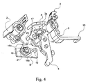
- FIGS. 4 to 6 Another version of the device according to the invention appears in FIGS. 4 to 6.
- a control member (2) is connected via a connecting rod (3) to a contact carrier (s) (17) to which the movable contact (4) is rigidly connected, a trigger (5) being pivoted about a pivot (18) protruding from the contact carrier (s) (17).
- the spring (16) is a spiral spring having two end branches respectively (16a) and (16b), the latter being keyed in abutment on a relief (19) protruding from the housing B, the latter being in part occurrence symbolized by a rectangular portion of the envelope.
- the other end (16a) of the spiral spring (16) cooperates with a stud (20) protruding from the contact carrier (s) (17) which urges the spring (16) when the contact carrier (s) rotates in the direction clockwise.
- the central portion of the spiral spring (16) is wrapped around an inverted U-shaped housing (21) for accommodating a journal (22) protruding from the contact carrier (s) (17).
- This trunnion (22) is coaxial with the stud (18) around which the trigger (5) pivots.
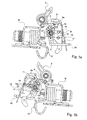
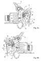
- Figures 5a and 5b show in two opposite incidences the operation of the lock mechanism, the movable contact (4) being here at a distance from the fixed contact (12).
- a bimetallic strip (13) is rigidly mounted on the movable contact (4). Its deformations allow, by contact with the coach (10), the pivoting of the trigger (5), and consequently the release of the end (3a) of the rod (3). Said pivoting can also be triggered by the striker (14) of the magnetic motor (M).
- the bimetallic strip (13) and the movable contact (4) constitute only one piece (4 ') producing the two fractions. In this case, so that the bending of the blade can intervene in good conditions, it is necessary that the attachment (23) to the contact carrier (s) (17) is made close to the contact area movable contact (4). ') / fixed contact (12).
Landscapes
- Switch Cases, Indication, And Locking (AREA)
- Current-Collector Devices For Electrically Propelled Vehicles (AREA)
- Lock And Its Accessories (AREA)
- Mobile Radio Communication Systems (AREA)
- Rotary Switch, Piano Key Switch, And Lever Switch (AREA)
- Ladders (AREA)
- Forklifts And Lifting Vehicles (AREA)
- Mechanisms For Operating Contacts (AREA)
- Switches With Compound Operations (AREA)
Priority Applications (14)
| Application Number | Priority Date | Filing Date | Title |
|---|---|---|---|
| DE602006009369T DE602006009369D1 (de) | 2006-02-03 | 2006-02-03 | Schaltschloss mit beweglicher Drehachse |
| ES06360005T ES2333156T3 (es) | 2006-02-03 | 2006-02-03 | Mecanismo de cerradura con eje movil. |
| PL06360005T PL1816665T3 (pl) | 2006-02-03 | 2006-02-03 | Mechanizm zamka z osią ruchomą |
| AT06360005T ATE443921T1 (de) | 2006-02-03 | 2006-02-03 | Schaltschloss mit beweglicher drehachse |
| EP06360005A EP1816665B1 (de) | 2006-02-03 | 2006-02-03 | Schaltschloss mit beweglicher Drehachse |
| RU2008135162/09A RU2398305C2 (ru) | 2006-02-03 | 2007-02-02 | Механизм блокировки с подвижным шпинделем |
| BRPI0706900-6A BRPI0706900B1 (pt) | 2006-02-03 | 2007-02-02 | Mecanismo de fechadura para aparelho elétrico |
| AU2007211406A AU2007211406B2 (en) | 2006-02-03 | 2007-02-02 | Mobile-spindle lock mechanism |
| CN2007800112448A CN101410926B (zh) | 2006-02-03 | 2007-02-02 | 可移动的心轴锁定机构 |
| MYPI20082932A MY143594A (en) | 2006-02-03 | 2007-02-02 | Mobile spindle lock mechanism |
| HK09105245.3A HK1126570B (en) | 2006-02-03 | 2007-02-02 | Mobile-spindle lock mechanism |
| PCT/FR2007/000192 WO2007088284A1 (fr) | 2006-02-03 | 2007-02-02 | Mecanisme de serrure a axe mobile |
| IL193201A IL193201A (en) | 2006-02-03 | 2008-08-03 | Mobile-spindle lock mechanism |
| ZA200807400A ZA200807400B (en) | 2006-02-03 | 2008-08-27 | Mobile-spindle lock mechanism |
Applications Claiming Priority (1)
| Application Number | Priority Date | Filing Date | Title |
|---|---|---|---|
| EP06360005A EP1816665B1 (de) | 2006-02-03 | 2006-02-03 | Schaltschloss mit beweglicher Drehachse |
Publications (2)
| Publication Number | Publication Date |
|---|---|
| EP1816665A1 true EP1816665A1 (de) | 2007-08-08 |
| EP1816665B1 EP1816665B1 (de) | 2009-09-23 |
Family
ID=36808983
Family Applications (1)
| Application Number | Title | Priority Date | Filing Date |
|---|---|---|---|
| EP06360005A Expired - Lifetime EP1816665B1 (de) | 2006-02-03 | 2006-02-03 | Schaltschloss mit beweglicher Drehachse |
Country Status (13)
| Country | Link |
|---|---|
| EP (1) | EP1816665B1 (de) |
| CN (1) | CN101410926B (de) |
| AT (1) | ATE443921T1 (de) |
| AU (1) | AU2007211406B2 (de) |
| BR (1) | BRPI0706900B1 (de) |
| DE (1) | DE602006009369D1 (de) |
| ES (1) | ES2333156T3 (de) |
| IL (1) | IL193201A (de) |
| MY (1) | MY143594A (de) |
| PL (1) | PL1816665T3 (de) |
| RU (1) | RU2398305C2 (de) |
| WO (1) | WO2007088284A1 (de) |
| ZA (1) | ZA200807400B (de) |
Cited By (2)
| Publication number | Priority date | Publication date | Assignee | Title |
|---|---|---|---|---|
| CN105590804A (zh) * | 2014-11-04 | 2016-05-18 | 西门子公司 | 断路器的分闸机构及其断路器 |
| EP4131314A1 (de) * | 2021-08-05 | 2023-02-08 | Hangzhou Taimu Electrical Co., Ltd. | Betaetigungsmechanismus eines schutzschalters |
Families Citing this family (4)
| Publication number | Priority date | Publication date | Assignee | Title |
|---|---|---|---|---|
| CN102254755B (zh) * | 2011-06-28 | 2013-10-16 | 法泰电器(江苏)股份有限公司 | 断路器操作机构 |
| CN103065887B (zh) * | 2013-01-09 | 2015-06-03 | 浙江天正电气股份有限公司 | 一种断路器延时脱扣装置 |
| CN104319203B (zh) * | 2014-11-13 | 2017-08-25 | 杭州泰姆电气有限公司 | 断路器操作机构 |
| WO2016173464A1 (zh) * | 2015-04-28 | 2016-11-03 | 上海电科电器科技有限公司 | 断路器的操作机构的二级锁扣机构 |
Citations (3)
| Publication number | Priority date | Publication date | Assignee | Title |
|---|---|---|---|---|
| EP0506503A1 (de) | 1991-03-29 | 1992-09-30 | Hager Electro S.A. | Schlossmechanismus für Lastschalter |
| EP0696041A1 (de) * | 1994-08-04 | 1996-02-07 | Legrand | Schutzschalter |
| US20020046940A1 (en) * | 2000-10-19 | 2002-04-25 | Didier Bruckert | Rapid closure mechanism for electrical contacts |
Family Cites Families (3)
| Publication number | Priority date | Publication date | Assignee | Title |
|---|---|---|---|---|
| DE4116454A1 (de) * | 1991-05-18 | 1992-11-19 | Licentia Gmbh | Mechanismus fuer einen selbstschalter |
| DE4442417C1 (de) * | 1994-11-29 | 1996-02-15 | Kloeckner Moeller Gmbh | Schaltschloß für ein Niederspannungs-Schaltgerät |
| FR2858109B1 (fr) * | 2003-07-24 | 2005-10-14 | Legrand Sa | Mecanisme de serrure a accrochage tournant pour coupe-circuit automatique de securite |
-
2006
- 2006-02-03 DE DE602006009369T patent/DE602006009369D1/de not_active Expired - Lifetime
- 2006-02-03 EP EP06360005A patent/EP1816665B1/de not_active Expired - Lifetime
- 2006-02-03 ES ES06360005T patent/ES2333156T3/es not_active Expired - Lifetime
- 2006-02-03 PL PL06360005T patent/PL1816665T3/pl unknown
- 2006-02-03 AT AT06360005T patent/ATE443921T1/de active
-
2007
- 2007-02-02 CN CN2007800112448A patent/CN101410926B/zh not_active Expired - Fee Related
- 2007-02-02 WO PCT/FR2007/000192 patent/WO2007088284A1/fr not_active Ceased
- 2007-02-02 RU RU2008135162/09A patent/RU2398305C2/ru active
- 2007-02-02 AU AU2007211406A patent/AU2007211406B2/en not_active Ceased
- 2007-02-02 BR BRPI0706900-6A patent/BRPI0706900B1/pt not_active IP Right Cessation
- 2007-02-02 MY MYPI20082932A patent/MY143594A/en unknown
-
2008
- 2008-08-03 IL IL193201A patent/IL193201A/en active IP Right Grant
- 2008-08-27 ZA ZA200807400A patent/ZA200807400B/xx unknown
Patent Citations (3)
| Publication number | Priority date | Publication date | Assignee | Title |
|---|---|---|---|---|
| EP0506503A1 (de) | 1991-03-29 | 1992-09-30 | Hager Electro S.A. | Schlossmechanismus für Lastschalter |
| EP0696041A1 (de) * | 1994-08-04 | 1996-02-07 | Legrand | Schutzschalter |
| US20020046940A1 (en) * | 2000-10-19 | 2002-04-25 | Didier Bruckert | Rapid closure mechanism for electrical contacts |
Cited By (3)
| Publication number | Priority date | Publication date | Assignee | Title |
|---|---|---|---|---|
| CN105590804A (zh) * | 2014-11-04 | 2016-05-18 | 西门子公司 | 断路器的分闸机构及其断路器 |
| CN105590804B (zh) * | 2014-11-04 | 2018-03-27 | 西门子公司 | 断路器的分闸机构及其断路器 |
| EP4131314A1 (de) * | 2021-08-05 | 2023-02-08 | Hangzhou Taimu Electrical Co., Ltd. | Betaetigungsmechanismus eines schutzschalters |
Also Published As
| Publication number | Publication date |
|---|---|
| HK1126570A1 (en) | 2009-09-04 |
| ATE443921T1 (de) | 2009-10-15 |
| PL1816665T3 (pl) | 2010-02-26 |
| IL193201A (en) | 2011-10-31 |
| RU2398305C2 (ru) | 2010-08-27 |
| RU2008135162A (ru) | 2010-03-10 |
| DE602006009369D1 (de) | 2009-11-05 |
| IL193201A0 (en) | 2009-02-11 |
| ZA200807400B (en) | 2009-10-28 |
| EP1816665B1 (de) | 2009-09-23 |
| AU2007211406B2 (en) | 2011-01-27 |
| BRPI0706900B1 (pt) | 2018-06-26 |
| AU2007211406A1 (en) | 2007-08-09 |
| ES2333156T3 (es) | 2010-02-17 |
| MY143594A (en) | 2011-05-31 |
| BRPI0706900A2 (pt) | 2011-04-12 |
| CN101410926A (zh) | 2009-04-15 |
| CN101410926B (zh) | 2013-04-17 |
| WO2007088284A1 (fr) | 2007-08-09 |
Similar Documents
| Publication | Publication Date | Title |
|---|---|---|
| EP3581742B1 (de) | Flächenbündiger türgriff und verfahren zum betrieb davon | |
| EP2460172B1 (de) | Drehbares steuersystem für einen stromschutzschalter | |
| EP0179002B1 (de) | Einrichtung zum automatischen Schliessen, sowie zum Offenhalten von Türen | |
| WO2007088284A1 (fr) | Mecanisme de serrure a axe mobile | |
| EP1975971B1 (de) | Bedienungsvorrichtung eines elektrischen Sicherungsgeräts und elektrisches Sicherungsgerät, das sie umfasst | |
| FR2742638A1 (fr) | Dispositif de fixation d'une extremite d'un lien a un objet, notamment une montre | |
| EP0570647A1 (de) | Schaltschloss für Schutzschalter und Schutzschalter, mit diesem integriert | |
| EP2061059A1 (de) | Steuervorrichtung für ein elektrisches Unterbrechungsgerät und elektrisches Unterbrechungsgerät, das damit ausgestattet ist | |
| EP2061058B1 (de) | Steuervorrichtung für ein elektrisches Unterbrechungsgerät und elektrisches Unterbrechungsgerät, das damit ausgestattet ist | |
| FR2552930A1 (fr) | Mecanisme de commutation pour interrupteur de securite de ligne | |
| FR2813706A1 (fr) | Coupe circuit et commutateurs d'accessoires de celui-ci | |
| EP0657909A1 (de) | Elektrischer Schalter mit Fehlerauslosung | |
| FR2928774A1 (fr) | Mecanisme de serrure a biellette elastique. | |
| FR2769037A1 (fr) | Dispositif de verrouillage comportant un doigt de transmission commande par came | |
| EP0209433A1 (de) | Kontaktträger, insbesondere für Schutzschalter | |
| EP0032870B1 (de) | Auf ein Gestell montierbares Gerät zum Steuern der Bewegung eines Armes und Anwendung dieses Gerätes als Schalter | |
| FR2892849A1 (fr) | Mecanisme a serrure pour appareil electrique | |
| EP1383150B1 (de) | Schalter mit Auslöseeinrichtung | |
| EP1998352A1 (de) | Kontaktvorrichtung für ein elektrisches Gerät und Signalisierungshilfsgerät, das eine solche Vorrichtung umfasst | |
| EP3091557B1 (de) | Bedienungsvorrichtung eines elektrischen sicherungsgeräts und diese umfassendes elektrisches sicherungsgerät | |
| FR2626712A1 (fr) | Interrupteur electrique a coupure automatique, en particulier interrupteur differentiel | |
| FR2944826A1 (fr) | Serrure a pene coulant verrouillable par genouillere | |
| FR2796488A1 (fr) | Dispositif pour activer et desactiver des appareils de commutation agences sous forme de bloc | |
| EP4542603A1 (de) | Unterbrechungsvorrichtung mit einem klopfmittel | |
| FR2530072A1 (fr) | Dispositif commutateur, notamment disjoncteur du type a enclenchement par enfoncement puis relachement d'un bouton-poussoir et a declenchement par la deformation d'une lame bimetallique |
Legal Events
| Date | Code | Title | Description |
|---|---|---|---|
| PUAI | Public reference made under article 153(3) epc to a published international application that has entered the european phase |
Free format text: ORIGINAL CODE: 0009012 |
|
| AK | Designated contracting states |
Kind code of ref document: A1 Designated state(s): AT BE BG CH CY CZ DE DK EE ES FI FR GB GR HU IE IS IT LI LT LU LV MC NL PL PT RO SE SI SK TR |
|
| AX | Request for extension of the european patent |
Extension state: AL BA HR MK YU |
|
| 17P | Request for examination filed |
Effective date: 20070907 |
|
| AKX | Designation fees paid |
Designated state(s): AT BE BG CH CY CZ DE DK EE ES FI FR GB GR HU IE IS IT LI LT LU LV MC NL PL PT RO SE SI SK TR |
|
| GRAP | Despatch of communication of intention to grant a patent |
Free format text: ORIGINAL CODE: EPIDOSNIGR1 |
|
| GRAS | Grant fee paid |
Free format text: ORIGINAL CODE: EPIDOSNIGR3 |
|
| GRAA | (expected) grant |
Free format text: ORIGINAL CODE: 0009210 |
|
| AK | Designated contracting states |
Kind code of ref document: B1 Designated state(s): AT BE BG CH CY CZ DE DK EE ES FI FR GB GR HU IE IS IT LI LT LU LV MC NL PL PT RO SE SI SK TR |
|
| REG | Reference to a national code |
Ref country code: GB Ref legal event code: FG4D Free format text: NOT ENGLISH |
|
| REG | Reference to a national code |
Ref country code: CH Ref legal event code: EP |
|
| REG | Reference to a national code |
Ref country code: IE Ref legal event code: FG4D |
|
| REF | Corresponds to: |
Ref document number: 602006009369 Country of ref document: DE Date of ref document: 20091105 Kind code of ref document: P |
|
| REG | Reference to a national code |
Ref country code: RO Ref legal event code: EPE |
|
| REG | Reference to a national code |
Ref country code: SE Ref legal event code: TRGR |
|
| PG25 | Lapsed in a contracting state [announced via postgrant information from national office to epo] |
Ref country code: LT Free format text: LAPSE BECAUSE OF FAILURE TO SUBMIT A TRANSLATION OF THE DESCRIPTION OR TO PAY THE FEE WITHIN THE PRESCRIBED TIME-LIMIT Effective date: 20090923 Ref country code: FI Free format text: LAPSE BECAUSE OF FAILURE TO SUBMIT A TRANSLATION OF THE DESCRIPTION OR TO PAY THE FEE WITHIN THE PRESCRIBED TIME-LIMIT Effective date: 20090923 |
|
| REG | Reference to a national code |
Ref country code: ES Ref legal event code: FG2A Ref document number: 2333156 Country of ref document: ES Kind code of ref document: T3 |
|
| LTIE | Lt: invalidation of european patent or patent extension |
Effective date: 20090923 |
|
| PG25 | Lapsed in a contracting state [announced via postgrant information from national office to epo] |
Ref country code: SI Free format text: LAPSE BECAUSE OF FAILURE TO SUBMIT A TRANSLATION OF THE DESCRIPTION OR TO PAY THE FEE WITHIN THE PRESCRIBED TIME-LIMIT Effective date: 20090923 Ref country code: LV Free format text: LAPSE BECAUSE OF FAILURE TO SUBMIT A TRANSLATION OF THE DESCRIPTION OR TO PAY THE FEE WITHIN THE PRESCRIBED TIME-LIMIT Effective date: 20090923 |
|
| REG | Reference to a national code |
Ref country code: PL Ref legal event code: T3 |
|
| NLV1 | Nl: lapsed or annulled due to failure to fulfill the requirements of art. 29p and 29m of the patents act | ||
| PG25 | Lapsed in a contracting state [announced via postgrant information from national office to epo] |
Ref country code: CY Free format text: LAPSE BECAUSE OF FAILURE TO SUBMIT A TRANSLATION OF THE DESCRIPTION OR TO PAY THE FEE WITHIN THE PRESCRIBED TIME-LIMIT Effective date: 20090923 |
|
| REG | Reference to a national code |
Ref country code: IE Ref legal event code: FD4D |
|
| PG25 | Lapsed in a contracting state [announced via postgrant information from national office to epo] |
Ref country code: IE Free format text: LAPSE BECAUSE OF FAILURE TO SUBMIT A TRANSLATION OF THE DESCRIPTION OR TO PAY THE FEE WITHIN THE PRESCRIBED TIME-LIMIT Effective date: 20090923 Ref country code: PT Free format text: LAPSE BECAUSE OF FAILURE TO SUBMIT A TRANSLATION OF THE DESCRIPTION OR TO PAY THE FEE WITHIN THE PRESCRIBED TIME-LIMIT Effective date: 20100125 Ref country code: CZ Free format text: LAPSE BECAUSE OF FAILURE TO SUBMIT A TRANSLATION OF THE DESCRIPTION OR TO PAY THE FEE WITHIN THE PRESCRIBED TIME-LIMIT Effective date: 20090923 Ref country code: EE Free format text: LAPSE BECAUSE OF FAILURE TO SUBMIT A TRANSLATION OF THE DESCRIPTION OR TO PAY THE FEE WITHIN THE PRESCRIBED TIME-LIMIT Effective date: 20090923 Ref country code: IS Free format text: LAPSE BECAUSE OF FAILURE TO SUBMIT A TRANSLATION OF THE DESCRIPTION OR TO PAY THE FEE WITHIN THE PRESCRIBED TIME-LIMIT Effective date: 20100123 |
|
| PG25 | Lapsed in a contracting state [announced via postgrant information from national office to epo] |
Ref country code: SK Free format text: LAPSE BECAUSE OF FAILURE TO SUBMIT A TRANSLATION OF THE DESCRIPTION OR TO PAY THE FEE WITHIN THE PRESCRIBED TIME-LIMIT Effective date: 20090923 |
|
| PG25 | Lapsed in a contracting state [announced via postgrant information from national office to epo] |
Ref country code: DK Free format text: LAPSE BECAUSE OF FAILURE TO SUBMIT A TRANSLATION OF THE DESCRIPTION OR TO PAY THE FEE WITHIN THE PRESCRIBED TIME-LIMIT Effective date: 20090923 Ref country code: NL Free format text: LAPSE BECAUSE OF FAILURE TO SUBMIT A TRANSLATION OF THE DESCRIPTION OR TO PAY THE FEE WITHIN THE PRESCRIBED TIME-LIMIT Effective date: 20090923 |
|
| PLBE | No opposition filed within time limit |
Free format text: ORIGINAL CODE: 0009261 |
|
| STAA | Information on the status of an ep patent application or granted ep patent |
Free format text: STATUS: NO OPPOSITION FILED WITHIN TIME LIMIT |
|
| BERE | Be: lapsed |
Owner name: HAGER-ELECTRO SAS Effective date: 20100228 |
|
| 26N | No opposition filed |
Effective date: 20100624 |
|
| REG | Reference to a national code |
Ref country code: CH Ref legal event code: PL |
|
| PG25 | Lapsed in a contracting state [announced via postgrant information from national office to epo] |
Ref country code: LI Free format text: LAPSE BECAUSE OF NON-PAYMENT OF DUE FEES Effective date: 20100228 Ref country code: CH Free format text: LAPSE BECAUSE OF NON-PAYMENT OF DUE FEES Effective date: 20100228 Ref country code: GR Free format text: LAPSE BECAUSE OF FAILURE TO SUBMIT A TRANSLATION OF THE DESCRIPTION OR TO PAY THE FEE WITHIN THE PRESCRIBED TIME-LIMIT Effective date: 20091224 Ref country code: MC Free format text: LAPSE BECAUSE OF NON-PAYMENT OF DUE FEES Effective date: 20100301 |
|
| PG25 | Lapsed in a contracting state [announced via postgrant information from national office to epo] |
Ref country code: BE Free format text: LAPSE BECAUSE OF NON-PAYMENT OF DUE FEES Effective date: 20100228 |
|
| PG25 | Lapsed in a contracting state [announced via postgrant information from national office to epo] |
Ref country code: HU Free format text: LAPSE BECAUSE OF FAILURE TO SUBMIT A TRANSLATION OF THE DESCRIPTION OR TO PAY THE FEE WITHIN THE PRESCRIBED TIME-LIMIT Effective date: 20100324 Ref country code: LU Free format text: LAPSE BECAUSE OF NON-PAYMENT OF DUE FEES Effective date: 20100203 Ref country code: BG Free format text: LAPSE BECAUSE OF FAILURE TO SUBMIT A TRANSLATION OF THE DESCRIPTION OR TO PAY THE FEE WITHIN THE PRESCRIBED TIME-LIMIT Effective date: 20090923 |
|
| REG | Reference to a national code |
Ref country code: FR Ref legal event code: PLFP Year of fee payment: 11 |
|
| REG | Reference to a national code |
Ref country code: FR Ref legal event code: PLFP Year of fee payment: 12 |
|
| REG | Reference to a national code |
Ref country code: FR Ref legal event code: PLFP Year of fee payment: 13 |
|
| PGFP | Annual fee paid to national office [announced via postgrant information from national office to epo] |
Ref country code: RO Payment date: 20230120 Year of fee payment: 18 |
|
| PGFP | Annual fee paid to national office [announced via postgrant information from national office to epo] |
Ref country code: TR Payment date: 20230130 Year of fee payment: 18 |
|
| P01 | Opt-out of the competence of the unified patent court (upc) registered |
Effective date: 20230606 |
|
| PGFP | Annual fee paid to national office [announced via postgrant information from national office to epo] |
Ref country code: ES Payment date: 20240301 Year of fee payment: 19 |
|
| PGFP | Annual fee paid to national office [announced via postgrant information from national office to epo] |
Ref country code: AT Payment date: 20240119 Year of fee payment: 19 |
|
| PGFP | Annual fee paid to national office [announced via postgrant information from national office to epo] |
Ref country code: DE Payment date: 20240228 Year of fee payment: 19 Ref country code: GB Payment date: 20240227 Year of fee payment: 19 |
|
| PGFP | Annual fee paid to national office [announced via postgrant information from national office to epo] |
Ref country code: SE Payment date: 20240307 Year of fee payment: 19 Ref country code: PL Payment date: 20240118 Year of fee payment: 19 Ref country code: IT Payment date: 20240222 Year of fee payment: 19 Ref country code: FR Payment date: 20240226 Year of fee payment: 19 |
|
| PG25 | Lapsed in a contracting state [announced via postgrant information from national office to epo] |
Ref country code: RO Free format text: LAPSE BECAUSE OF NON-PAYMENT OF DUE FEES Effective date: 20240203 |
|
| REG | Reference to a national code |
Ref country code: DE Ref legal event code: R119 Ref document number: 602006009369 Country of ref document: DE |
|
| REG | Reference to a national code |
Ref country code: SE Ref legal event code: EUG |
|
| REG | Reference to a national code |
Ref country code: AT Ref legal event code: MM01 Ref document number: 443921 Country of ref document: AT Kind code of ref document: T Effective date: 20250203 |
|
| PG25 | Lapsed in a contracting state [announced via postgrant information from national office to epo] |
Ref country code: AT Free format text: LAPSE BECAUSE OF NON-PAYMENT OF DUE FEES Effective date: 20250203 |
|
| GBPC | Gb: european patent ceased through non-payment of renewal fee |
Effective date: 20250203 |
|
| PG25 | Lapsed in a contracting state [announced via postgrant information from national office to epo] |
Ref country code: DE Free format text: LAPSE BECAUSE OF NON-PAYMENT OF DUE FEES Effective date: 20250902 |
|
| PG25 | Lapsed in a contracting state [announced via postgrant information from national office to epo] |
Ref country code: GB Free format text: LAPSE BECAUSE OF NON-PAYMENT OF DUE FEES Effective date: 20250203 |
|
| PG25 | Lapsed in a contracting state [announced via postgrant information from national office to epo] |
Ref country code: FR Free format text: LAPSE BECAUSE OF NON-PAYMENT OF DUE FEES Effective date: 20250228 Ref country code: IT Free format text: LAPSE BECAUSE OF NON-PAYMENT OF DUE FEES Effective date: 20250203 |
|
| REG | Reference to a national code |
Ref country code: ES Ref legal event code: FD2A Effective date: 20260326 |
|
| PG25 | Lapsed in a contracting state [announced via postgrant information from national office to epo] |
Ref country code: ES Free format text: LAPSE BECAUSE OF NON-PAYMENT OF DUE FEES Effective date: 20250204 |