EP1817093B1 - Fuel filter assembly - Google Patents
Fuel filter assembly Download PDFInfo
- Publication number
- EP1817093B1 EP1817093B1 EP05796601A EP05796601A EP1817093B1 EP 1817093 B1 EP1817093 B1 EP 1817093B1 EP 05796601 A EP05796601 A EP 05796601A EP 05796601 A EP05796601 A EP 05796601A EP 1817093 B1 EP1817093 B1 EP 1817093B1
- Authority
- EP
- European Patent Office
- Prior art keywords
- fuel filter
- end cap
- keys
- filtering media
- filter assembly
- Prior art date
- Legal status (The legal status is an assumption and is not a legal conclusion. Google has not performed a legal analysis and makes no representation as to the accuracy of the status listed.)
- Expired - Lifetime
Links
Images



Classifications
-
- B—PERFORMING OPERATIONS; TRANSPORTING
- B01—PHYSICAL OR CHEMICAL PROCESSES OR APPARATUS IN GENERAL
- B01D—SEPARATION
- B01D35/00—Filtering devices having features not specifically covered by groups B01D24/00 - B01D33/00, or for applications not specifically covered by groups B01D24/00 - B01D33/00; Auxiliary devices for filtration; Filter housing constructions
- B01D35/14—Safety devices specially adapted for filtration; Devices for indicating clogging
- B01D35/153—Anti-leakage or anti-return valves
-
- B—PERFORMING OPERATIONS; TRANSPORTING
- B01—PHYSICAL OR CHEMICAL PROCESSES OR APPARATUS IN GENERAL
- B01D—SEPARATION
- B01D29/00—Filters with filtering elements stationary during filtration, e.g. pressure or suction filters, not covered by groups B01D24/00 - B01D27/00; Filtering elements therefor
- B01D29/11—Filters with filtering elements stationary during filtration, e.g. pressure or suction filters, not covered by groups B01D24/00 - B01D27/00; Filtering elements therefor with bag, cage, hose, tube, sleeve or like filtering elements
- B01D29/13—Supported filter elements
- B01D29/15—Supported filter elements arranged for inward flow filtration
- B01D29/21—Supported filter elements arranged for inward flow filtration with corrugated, folded or wound sheets
-
- B—PERFORMING OPERATIONS; TRANSPORTING
- B01—PHYSICAL OR CHEMICAL PROCESSES OR APPARATUS IN GENERAL
- B01D—SEPARATION
- B01D29/00—Filters with filtering elements stationary during filtration, e.g. pressure or suction filters, not covered by groups B01D24/00 - B01D27/00; Filtering elements therefor
- B01D29/96—Filters with filtering elements stationary during filtration, e.g. pressure or suction filters, not covered by groups B01D24/00 - B01D27/00; Filtering elements therefor in which the filtering elements are moved between filtering operations; Particular measures for removing or replacing the filtering elements; Transport systems for filters
-
- B—PERFORMING OPERATIONS; TRANSPORTING
- B01—PHYSICAL OR CHEMICAL PROCESSES OR APPARATUS IN GENERAL
- B01D—SEPARATION
- B01D2201/00—Details relating to filtering apparatus
- B01D2201/29—Filter cartridge constructions
- B01D2201/291—End caps
-
- B—PERFORMING OPERATIONS; TRANSPORTING
- B01—PHYSICAL OR CHEMICAL PROCESSES OR APPARATUS IN GENERAL
- B01D—SEPARATION
- B01D2201/00—Details relating to filtering apparatus
- B01D2201/40—Special measures for connecting different parts of the filter
- B01D2201/4046—Means for avoiding false mounting of different parts
-
- B—PERFORMING OPERATIONS; TRANSPORTING
- B01—PHYSICAL OR CHEMICAL PROCESSES OR APPARATUS IN GENERAL
- B01D—SEPARATION
- B01D2201/00—Details relating to filtering apparatus
- B01D2201/40—Special measures for connecting different parts of the filter
- B01D2201/4084—Snap or Seeger ring connecting means
Definitions
- the present invention generally relates a fuel filter assembly.
- the present invention relates to keyed fuel filter cartridges for a fuel filter housing which has a keyed latch shut-off valve as shown for example in U.S. Patent Nos. 6,495,042 and 6,550,000 .
- stepped keys are provided in a recess formed in the bottom end cap of a fuel filter cartridge.
- Each of the stepped keys includes a valve actuation portion and a latch actuation portion, whereby the keys are used to unlock a latched device and move a valve element and uncover a fuel flow port in a standpipe of a valve housing. It is known that these fuel filter cartridges are periodically replaced from time to time, but the fuel filter housing is permanent and typically reused.
- the present invention relates to a fuel filter cartridge and end cap which may be used and applied to such fuel filter housings as disclosed in the '042 and '000 patents referenced above, or that may have other application.
- the fuel filter includes a tube of filter media surrounding a longitudinal axis.
- a first end cap is placed on the first end of the tube of filtering media.
- the first end cap defines a first annular trough that is filled with potting compound to connect and seal the first end cap to the tube of filtering media.
- the first end cap defines a first central opening surrounding the longitudinal axis.
- a second end cap is located on the second end of the tube of filtering media.
- the second end cap includes an outer annular skirt portion, an inner annular skirt port and a disc portion therebetween.
- the second end cap defines a second annular trough along the disc portion between the skirt portions which has potting compound therein which connects and seals the first end cap to the tube of filtering media.
- the second end cap defines a second central opening which surrounds the longitudinal axis.
- a plurality of keys are located on the disc portion and project axially from the disc portion in a direction away from the filtering media. The keys are arranged in an annular array surrounding the axis.
- the end cap includes an outer annular skirt portion, an inner annular skirt portion and a disc portion therebetween.
- An annular trough is formed along the disc portion between the skirt portions on an underside of the end cap.
- a central opening is formed into the disc portion and surrounds the longitudinal axis.
- a plurality of keys are located on the disc portion and project axially from the disc portion. These keys are arranged in an annular array which surrounds the axis.
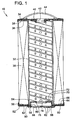
- FIG. 1 is a cross-section of a fuel filter cartridge in accordance with a first embodiment of the present invention.
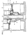
- FIG. 2 is a cross-section of the bottom end cap portion of the fuel filter cartridge shown in FIG. 1 as installed on a standpipe in a fuel filter housing and engaging a latch and valve mechanism therein.
- FIG. 3 is an isometric view of the bottom end cap of the fuel filter cartridge of FIG. 1 .
- FIG. 4 is a view similar to FIG. 3 , but with the end cap cut in half.
- FIG. 5 is a bottom end view of the bottom end cap for the fuel filter of the first embodiment shown in FIG. 1 .
- FIG. 6 is a cross-section of FIG. 5 taken about line 6-6.
- FIGS. 7 and 8 are enlarged views of different portions of FIG. 6 .
- FIG. 9 is a view of a bottom end cap of a second embodiment of the present invention for a fuel filter cartridge.
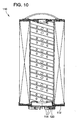
- FIG. 10 is a view of the end cap of the second embodiment as mounted on a filter cartridge.
- FIG. 11 is a plan bottom view of the second embodiment of the end cap shown in FIG. 9 .
- FIG. 12 is a cross-section of FIG. 11 taken about line 12-12.
- FIGS. 13 and 14 are enlarged views of different portions of FIG. 12 .
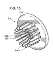
- FIG. 15 is an isometric view of a third embodiment of the end cap which may be used on a filter cartridge.
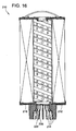
- FIG. 16 is a view of the third embodiment of the end cap shown in FIG. 15 as mounted on a fuel filter cartridge.
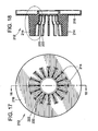
- FIG. 17 is a bottom plan view of the end cap according to the third embodiment shown in FIG. 15 .
- FIG. 18 is a cross-section of the end cap shown in FIG. 17 .
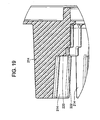
- FIG. 19 is an enlarged view of a portion of FIG. 18 .
- the invention is embodied in a fuel filter cartridge 10 as shown in FIG 1 .
- a fuel filter housing 12 depicts an exemplary environment in which the fuel filter cartridge 10 will operate.
- the fuel filter housing includes a container 14 into which the fuel filter cartridge 10 is axially inserted along a longitudinal axis 16 (longitudinal axis 16 also designated the central axis for the fuel filter cartridge 10).
- a fuel standpipe 18 Concentric and co-axis with the longitudinal axis is a fuel standpipe 18 which carries a spring loaded latch device 20 in the form of a sleeve and a flow control valve 22 which opens and closes a fuel flow port 24 that extends radially through the standpipe 18.
- a spring loaded latch device 20 in the form of a sleeve
- a flow control valve 22 which opens and closes a fuel flow port 24 that extends radially through the standpipe 18.
- FIG. 2 different halves of the longitudinal axis 16 depict different engagement positions at different stages of axial insertion of the fuel filter cartridge 10 into the fuel filter housing 12.
- the fuel filter cartridge 10 will first engage the latch device 20 and then subsequently engage the valve 22 to uncover the flow port to allow for fuel flow from the central region of the fuel filter cartridge 10 into the standpipe 18. Further details of such a fuel filter housing and standpipe can be had to the referenced patents set forth in the background above.
- the fuel filter cartridge 10 generally includes a cylindrical tube of filtering media 30 that is concentric around the longitudinal axis 16.
- the tube of filtering media 30 may comprise a cylindrical ring of pleated filter paper, or may comprise other suitable filtering media.
- a perforated metal or plastic central support tube 32 may be provided concentrically inside the filtering media 30 to provide for radial support to the filtering media 30.
- the support tube 32 provides support for the media 30 when fuel is flowing radially inward through the filtering media 30.
- top end cap 34 At the top end of the filter cartridge 10 with the given orientation shown in FIG. 1 , there is a top end cap 34.
- the top end cap 34 defines an annular trough 36 along the underside thereof.
- the annular trough 36 that receives potting compound 38 (such as plastisol, adhesive or other suitable bonding agent) which connects and seals the top end cap 34 to the top end of the filtering media 30.
- the top end cap 34 defines a central opening 40 which is sized to receive the standpipe 18 therethrough.
- the top end cap 34 carries an annular gasket 42 which engages and seals against the standpipe 18 shown in FIG. 2 when installed into the fuel filter housing 12.
- a collapsible handle 44 may also be mounted to the top end cap 34 to provide a means for ready removal of the fuel filter cartridge at filter change interval time. The handle 44 can be pulled to facilitate removal of the fuel filter cartridge.
- the bottom end cap 50 may be comprised of two separate component plastic parts including a generally plate-shaped member 52 and a generally ring-shaped member 54 which are assembled together as shown.
- One method for assembling the two members 52 and 54 together is a snap-lock connection in which snap tabs 56 projecting from one of the members 54 is snapped onto corresponding structure on the other member 52 to form the bottom end cap 50.
- the bottom end cap 50 once assembled includes an outer annular skirt 58, an inner skirt 60 and a generally planar disc portion 62 therebetween.
- the combination of these structural portions provides an annular trough 64 which is received onto the bottom end of the filtering media 30 and connected and sealed thereto by potting compound 66.
- the inner periphery of the disc portion 62 defines a central opening 68 which may be recessed into the filtering media 30 as indicted via the inner skirt 60.
- the inner skirt 60 extends axially inward and terminates in a radially inward extending bottom wall 70 to form a generally cylindrical recess 72.
- the bottom wall 70 is generally planar in nature and extends radially inward toward a further central opening 74 that is of a smaller diameter than the outer central opening 68.
- the bottom wall 70 in this embodiment is used as the valve actuation means as shown in FIG. 2 .
- a loop structure or lip 76 Surrounding the central opening 74 is a loop structure or lip 76 which is configured to slidably engage the standpipe and provides for some flexibility to allow for easier axial installation and location features.
- the lip 76 which extends axially also flexes slightly inwardly and outwardly radially relative to the standpipe.
- the bottom end cap 50 also provides means for engaging the latch device which is shown in the form of an annular array of keys 82.
- the keys 82 are not located in the recess 72 but are located on the disc portion 62 and project axially from the disc portion 62 in an outward direction, which is away from the filtering media 30.
- the keys 82 are arranged in an annular array which surrounds the central longitudinal axis 16.
- the keys 82 project radially inward past the outer central opening 68 in a cantilever manner such that gaps 84 are formed between adjacent keys to provide suitable clearance for use with the associated standpipe and valve/latch mechanism.
- the keys are arranged and spaced to provide means for releasing the latch device 20 of the flow control valve 22 in the filter housing.
- the keys 82 are configured and spaced relative to the valve actuating bottom wall 70 so as to compliment the configuration of the latch device 20 and valve 22 of the fuel filter housing. To achieve this, the keys 82 only extend partially radially inward and short of the diameter of the inner central opening 74. With this configuration, there is no longer a requirement that the outer face of the keys be stepped.
- the keys 82 may have an outer surface 88 which is relatively straight in the radial direction.
- the keys 82 may also be elevated slightly by a raised annular plateau portion 90 which is formed into the disc portion 62 of the plate-shaped member 52.
- This raised plateau portion 90 also provides along the inward side a recess area to receive a radial projection of the ring-shaped member 54 and thereby provide a flat underside surface for the annular trough 64 to better ensure connection and sealing between the bottom end cap 50 and the filtering media 30 via the potting compound 66.
- a disposable fuel filter cartridge 110 is illustrated which will be understood to be similar in most material respects to FIG. 1 , with the primary exception being the configuration and keying mechanism of the bottom end cap 112. Accordingly, focus as applied to this embodiment will be directed to the principle distinctions.
- the bottom end cap 112 still includes keys 114 which project from the disc portion 116 of the bottom end cap 112. Similar to the first embodiment, the keys 114 avoid and are clear of the recess structure 118 formed into the bottom end cap 112. However, as opposed to the first embodiment where the bottom wall of the recess provides the valve actuation means, in this embodiment the keys 114 themselves provide for both the latch actuation means and the valve actuation means.
- the keys 114 are stepped to include a first latch actuation surface 120 and a second valve actuation surface 122.
- These surfaces 120, 122 are both axially and radially spaced with a configuration and spacing that is complimentary to that of the latch device and valve of a corresponding fuel filter housing.
- the fuel filter cartridge 210 of the third embodiment is much like the earlier two embodiments with a principle distinction being the configuration and shape of the bottom end cap 212.
- the bottom end cap 212 may be formed of a single unitary member rather than two component part members which are assembled together. Further, this embodiment eliminates the recess structure of prior embodiments and instead the keys 214 are formed on the outer face or disc portion 216 of the bottom end cap projecting axially outward therefrom (in a direction away from the filtering media).
- these keys 214 also include a stepped surface to include a latch actuation surface 120 and a valve actuation surface 122 which are both radially and axially spaced relative to each other.
- a potential advantage of an embodiment like this is that the inner diameter of the filtering media may be moved inwardly if desired (e.g. the inner diameter of the filtering media may be smaller).
Landscapes
- Chemical & Material Sciences (AREA)
- Chemical Kinetics & Catalysis (AREA)
- Filtration Of Liquid (AREA)
- Lubrication Details And Ventilation Of Internal Combustion Engines (AREA)
- Filtering Of Dispersed Particles In Gases (AREA)
Abstract
Description
- The present invention generally relates a fuel filter assembly.
- The present invention relates to keyed fuel filter cartridges for a fuel filter housing which has a keyed latch shut-off valve as shown for example in
U.S. Patent Nos. 6,495,042 and6,550,000 . As disclosed generally in these patents, stepped keys are provided in a recess formed in the bottom end cap of a fuel filter cartridge. Each of the stepped keys includes a valve actuation portion and a latch actuation portion, whereby the keys are used to unlock a latched device and move a valve element and uncover a fuel flow port in a standpipe of a valve housing. It is known that these fuel filter cartridges are periodically replaced from time to time, but the fuel filter housing is permanent and typically reused. In these applications the fuel filter cartridge is pulled from the fuel filter housing which returns the valve to the closed position and the latch mechanism to the lock position. As a result, when a new filter cartridge is installed there is a need to be able to again unlatch the latch device and then move the valve element to uncover the opening in the standpipe. The present invention relates to a fuel filter cartridge and end cap which may be used and applied to such fuel filter housings as disclosed in the '042 and '000 patents referenced above, or that may have other application. - According to the present invention an improved filter assembly is subject matter of claim 1.
- Further advantageous embodiments are subject matter of claims 2 to 12.
- One aspect of the present invention is directed toward a fuel filter. The fuel filter includes a tube of filter media surrounding a longitudinal axis. A first end cap is placed on the first end of the tube of filtering media. The first end cap defines a first annular trough that is filled with potting compound to connect and seal the first end cap to the tube of filtering media. The first end cap defines a first central opening surrounding the longitudinal axis. A second end cap is located on the second end of the tube of filtering media. The second end cap includes an outer annular skirt portion, an inner annular skirt port and a disc portion therebetween. The second end cap defines a second annular trough along the disc portion between the skirt portions which has potting compound therein which connects and seals the first end cap to the tube of filtering media. The second end cap defines a second central opening which surrounds the longitudinal axis. Unlike the prior art, a plurality of keys are located on the disc portion and project axially from the disc portion in a direction away from the filtering media. The keys are arranged in an annular array surrounding the axis.
- Another aspect of the present invention is directed toward an end cap for such a fuel filter cartridge. The end cap includes an outer annular skirt portion, an inner annular skirt portion and a disc portion therebetween. An annular trough is formed along the disc portion between the skirt portions on an underside of the end cap. A central opening is formed into the disc portion and surrounds the longitudinal axis. A plurality of keys are located on the disc portion and project axially from the disc portion. These keys are arranged in an annular array which surrounds the axis.
- Other aspects, objectives and advantages of the invention will become more apparent from the following detailed description when taken in conjunction with the accompanying drawings.
-
FIG. 1 is a cross-section of a fuel filter cartridge in accordance with a first embodiment of the present invention. -
FIG. 2 is a cross-section of the bottom end cap portion of the fuel filter cartridge shown inFIG. 1 as installed on a standpipe in a fuel filter housing and engaging a latch and valve mechanism therein. -
FIG. 3 is an isometric view of the bottom end cap of the fuel filter cartridge ofFIG. 1 . -
FIG. 4 is a view similar toFIG. 3 , but with the end cap cut in half. -
FIG. 5 is a bottom end view of the bottom end cap for the fuel filter of the first embodiment shown inFIG. 1 . -
FIG. 6 is a cross-section ofFIG. 5 taken about line 6-6. -
FIGS. 7 and 8 are enlarged views of different portions ofFIG. 6 . -
FIG. 9 is a view of a bottom end cap of a second embodiment of the present invention for a fuel filter cartridge. -
FIG. 10 is a view of the end cap of the second embodiment as mounted on a filter cartridge. -
FIG. 11 is a plan bottom view of the second embodiment of the end cap shown inFIG. 9 . -
FIG. 12 is a cross-section ofFIG. 11 taken about line 12-12. -
FIGS. 13 and 14 are enlarged views of different portions ofFIG. 12 . -
FIG. 15 is an isometric view of a third embodiment of the end cap which may be used on a filter cartridge. -
FIG. 16 is a view of the third embodiment of the end cap shown inFIG. 15 as mounted on a fuel filter cartridge. -
FIG. 17 is a bottom plan view of the end cap according to the third embodiment shown inFIG. 15 . -
FIG. 18 is a cross-section of the end cap shown inFIG. 17 . -
FIG. 19 is an enlarged view of a portion ofFIG. 18 . - While the invention will be described in connection with certain preferred embodiments, there is no intent to limit it to those embodiments. On the contrary, the intent is to cover all alternatives, modifications and equivalents as included within the spirit and scope of the invention as defined by the appended claims.
- Referring to the first embodiment of
FIGS. 1-8 , the invention is embodied in afuel filter cartridge 10 as shown inFIG 1 . which is removably installed into a fuelfuel filter housing 12, the relevant portions of which are shown inFIG 2 . This ishousing 12 depicts an exemplary environment in which thefuel filter cartridge 10 will operate. As shown therein, the fuel filter housing includes acontainer 14 into which thefuel filter cartridge 10 is axially inserted along a longitudinal axis 16 (longitudinal axis 16 also designated the central axis for the fuel filter cartridge 10). Concentric and co-axis with the longitudinal axis is afuel standpipe 18 which carries a spring loadedlatch device 20 in the form of a sleeve and aflow control valve 22 which opens and closes afuel flow port 24 that extends radially through thestandpipe 18. As shown inFIG. 2 , different halves of thelongitudinal axis 16 depict different engagement positions at different stages of axial insertion of thefuel filter cartridge 10 into thefuel filter housing 12. As shown therein, thefuel filter cartridge 10 will first engage thelatch device 20 and then subsequently engage thevalve 22 to uncover the flow port to allow for fuel flow from the central region of thefuel filter cartridge 10 into thestandpipe 18. Further details of such a fuel filter housing and standpipe can be had to the referenced patents set forth in the background above. - With an exemplary operating environment for the present embodiment being understood, attention will now be directed toward the
fuel filter cartridge 10. Thefuel filter cartridge 10 generally includes a cylindrical tube of filteringmedia 30 that is concentric around thelongitudinal axis 16. The tube of filteringmedia 30 may comprise a cylindrical ring of pleated filter paper, or may comprise other suitable filtering media. A perforated metal or plasticcentral support tube 32 may be provided concentrically inside thefiltering media 30 to provide for radial support to thefiltering media 30. Thesupport tube 32 provides support for themedia 30 when fuel is flowing radially inward through thefiltering media 30. - At the top end of the
filter cartridge 10 with the given orientation shown inFIG. 1 , there is atop end cap 34. Thetop end cap 34 defines anannular trough 36 along the underside thereof. Theannular trough 36 that receives potting compound 38 (such as plastisol, adhesive or other suitable bonding agent) which connects and seals thetop end cap 34 to the top end of thefiltering media 30. Thetop end cap 34 defines acentral opening 40 which is sized to receive thestandpipe 18 therethrough. Along the inner lip of thecentral opening 40 thetop end cap 34 carries anannular gasket 42 which engages and seals against thestandpipe 18 shown inFIG. 2 when installed into thefuel filter housing 12. Acollapsible handle 44 may also be mounted to thetop end cap 34 to provide a means for ready removal of the fuel filter cartridge at filter change interval time. Thehandle 44 can be pulled to facilitate removal of the fuel filter cartridge. - Turning to the bottom side of the
filter cartridge 10, abottom end cap 50 is provided. Thebottom end cap 50 may be comprised of two separate component plastic parts including a generally plate-shapedmember 52 and a generally ring-shapedmember 54 which are assembled together as shown. One method for assembling the twomembers tabs 56 projecting from one of themembers 54 is snapped onto corresponding structure on theother member 52 to form thebottom end cap 50. - The
bottom end cap 50 once assembled includes an outerannular skirt 58, aninner skirt 60 and a generallyplanar disc portion 62 therebetween. The combination of these structural portions provides anannular trough 64 which is received onto the bottom end of thefiltering media 30 and connected and sealed thereto by potting compound 66. The inner periphery of thedisc portion 62 defines acentral opening 68 which may be recessed into thefiltering media 30 as indicted via theinner skirt 60. Theinner skirt 60 extends axially inward and terminates in a radially inward extendingbottom wall 70 to form a generallycylindrical recess 72. Thebottom wall 70 is generally planar in nature and extends radially inward toward a furthercentral opening 74 that is of a smaller diameter than the outercentral opening 68. Thebottom wall 70 in this embodiment is used as the valve actuation means as shown inFIG. 2 . Surrounding thecentral opening 74 is a loop structure orlip 76 which is configured to slidably engage the standpipe and provides for some flexibility to allow for easier axial installation and location features. Thelip 76 which extends axially also flexes slightly inwardly and outwardly radially relative to the standpipe. - Since the
valve 22 cannot be actuated without first removing theprotective latch device 20 as shown inFIG. 2 , thebottom end cap 50 also provides means for engaging the latch device which is shown in the form of an annular array ofkeys 82. Thekeys 82 are not located in therecess 72 but are located on thedisc portion 62 and project axially from thedisc portion 62 in an outward direction, which is away from thefiltering media 30. Thekeys 82 are arranged in an annular array which surrounds the centrallongitudinal axis 16. - As shown in the figures, the
keys 82 project radially inward past the outercentral opening 68 in a cantilever manner such thatgaps 84 are formed between adjacent keys to provide suitable clearance for use with the associated standpipe and valve/latch mechanism. The keys are arranged and spaced to provide means for releasing thelatch device 20 of theflow control valve 22 in the filter housing. Thekeys 82 are configured and spaced relative to the valve actuatingbottom wall 70 so as to compliment the configuration of thelatch device 20 andvalve 22 of the fuel filter housing. To achieve this, thekeys 82 only extend partially radially inward and short of the diameter of the innercentral opening 74. With this configuration, there is no longer a requirement that the outer face of the keys be stepped. Instead as shown thekeys 82 may have anouter surface 88 which is relatively straight in the radial direction. Thekeys 82 may also be elevated slightly by a raisedannular plateau portion 90 which is formed into thedisc portion 62 of the plate-shapedmember 52. This raisedplateau portion 90 also provides along the inward side a recess area to receive a radial projection of the ring-shapedmember 54 and thereby provide a flat underside surface for theannular trough 64 to better ensure connection and sealing between thebottom end cap 50 and thefiltering media 30 via the potting compound 66. - Turning to the second embodiment of the present invention shown in FIGS. 914, a disposable
fuel filter cartridge 110 is illustrated which will be understood to be similar in most material respects toFIG. 1 , with the primary exception being the configuration and keying mechanism of thebottom end cap 112. Accordingly, focus as applied to this embodiment will be directed to the principle distinctions. In this embodiment, thebottom end cap 112 still includeskeys 114 which project from thedisc portion 116 of thebottom end cap 112. Similar to the first embodiment, thekeys 114 avoid and are clear of therecess structure 118 formed into thebottom end cap 112. However, as opposed to the first embodiment where the bottom wall of the recess provides the valve actuation means, in this embodiment thekeys 114 themselves provide for both the latch actuation means and the valve actuation means. In particular, thekeys 114 are stepped to include a firstlatch actuation surface 120 and a secondvalve actuation surface 122. Thesesurfaces - Turning to a third embodiment of the present invention, with reference to
FIGS. 15-19 , it will be understood that thefuel filter cartridge 210 of the third embodiment is much like the earlier two embodiments with a principle distinction being the configuration and shape of thebottom end cap 212. In this embodiment, thebottom end cap 212 may be formed of a single unitary member rather than two component part members which are assembled together. Further, this embodiment eliminates the recess structure of prior embodiments and instead thekeys 214 are formed on the outer face ordisc portion 216 of the bottom end cap projecting axially outward therefrom (in a direction away from the filtering media). Similar to the second embodiment, thesekeys 214 also include a stepped surface to include alatch actuation surface 120 and avalve actuation surface 122 which are both radially and axially spaced relative to each other. A potential advantage of an embodiment like this is that the inner diameter of the filtering media may be moved inwardly if desired (e.g. the inner diameter of the filtering media may be smaller). - The use of the terms "a" and "an" and "the" and similar referents in the context of describing the invention (especially in the context of the following claims) is to be construed to cover both the singular and the plural, unless otherwise indicated herein or clearly contradicted by context. The terms "comprising," "having," "including," and "containing" are to be construed as open-ended terms (i.e., meaning "including, but not limited to,") unless otherwise noted. Recitation of ranges of values herein are merely intended to serve as a shorthand method of referring individually to each separate value falling within the range, unless otherwise indicated herein, and each separate value is incorporated into the specification as if it were individually recited herein. All methods described herein can be performed in any suitable order unless otherwise indicated herein or otherwise clearly contradicted by context. The use of any and all examples, or exemplary language (e.g., "such as") provided herein, is intended merely to better illuminate the invention and does not pose a limitation on the scope of the invention unless otherwise claimed. No language in the specification should be construed as indicating any non-claimed element as essential to the practice of the invention.
Claims (12)
- A fuel filter assembly comprising
a fuel filter housing (12) and a fuel filter cartridge (10, 110, 210), removeably installed in said fuel filter housing (12);
the fuel filter housing (12) including a container (14) into which the fuel filter cartridge (10, 110, 210) is axially inserted along a longitudinal central axis (16) and being provided with a fuel standpipe (18) concentric and coaxial with said longitudinal axis (16), said standpipe (18) carrying a spring loaded latch device (20) and a flow control valve (22) which opens and closes a fuel port (24) that extends radially through said standpipe (18) the latch device (20) is to be first engaged by a plurality of latch actuating keys (114, 124) of the fuel filter cartridge (10, 110, 210) before subsequently engaging the flow control valve (22)
and the fuel filter cartridge (10, 110, 210), comprising:a tube of filtering media (30) surrounding the longitudinal axis (16);a first end cap (34) defining a first annular trough (36) receiving a first end of the tube of filtering media (30), the first end cap (34) being connected and sealed to the tube of filtering media (30), the first end cap (34) defining a first central opening (40) surrounding the longitudinal axis (16);a second end cap (50, 112, 212) including an outer annular skirt portion (58), an inner annular skirt portion (60), and disc portion (62, 116, 216) therebetween, the second end cap (50, 112, 212) defining a second annular trough (64) along the disc portion (62, 116, 216) therebetween, the skirt portions (58, 60), the second annular trough (64) receiving a second end of the tube of filtering media (30), the second end cap (50, 112, 212) being connected and sealed to the tube of filtering media (30), the second end cap (50, 112, 212) defining a second central opening surrounding the longitudinal axis (16)and the second end cap (50, 112, 212) supporting the plurality of latch actuating keys (82, 114, 214);characterized in that
the plurality of latch actuating keys (82, 114, 214) are located on the disc portion (62, 116, 216) of the second end cap (50, 112, 212), are axially spaced from the filtering media (30) and projecting axially from the disc portion (62, 116, 216) in a direction away from the filtering media (30), the latch actuating keys (82, 114, 214) being arranged in an annular array surrounding the axis (16). - The fuel filter assembly of claim 1, wherein the latch actuating keys (82, 114) project radially inward over the second end cap opening (68), wherein gaps (84) are formed between adjacent latch actuating keys (82, 114).
- The fuel filter assembly of claims 1 or 2, wherein the second end cap (112, 212) further includes a cylindrical recess (118) having a bottom wall (70), the bottom wall (70) projecting radially inward from the inner skirt portion (60) and defining a third central opening (74) surrounding the axis (16) of a smaller diameter than the second central opening (68).
- The fuel filter assembly of claim 3, wherein the latch actuating keys (82, 114) are arranged and spaced to provide means for releasing the latch (20) of the valve (22) in the fuel filter housing (12), and wherein the bottom wall (70) is arranged relative to the keys (82, 114) to provide means for actuating the valve (22).
- The fuel filter assembly of claims 3 or 4, wherein the latch actuating keys (82, 114) are axially spaced from the cylindrical recess (118).
- The fuel filter assembly of any of claims 1 to 5, wherein the disc portion (62, 116) includes a raised annular plateau portion (90) projecting axially away from the filtering media (30), the latch actuating keys (114) being arranged on the raised annular plateau (90).
- The fuel filter assembly of any of claims 1 to 6, wherein the second end cap (50, 112) comprises different first and second component parts that are assembled together, the first component part providing the outer annular skirt portion (58) and the disc portion (62), the second component part providing the inner annular skirt portion (60) and a bottom wall (70) projecting radially inward from the inner annular skirt portion (60), the bottom wall being spaced axially from the disc portion (62) whereby a cylindrical recess (118) is formed into the second end cap (112, 212), the bottom wall portion (70) defining a third central opening (74) surrounding the axis (16) of a smaller diameter than the second central opening (68).
- The fuel filter assembly of claim 7, wherein the first component part is snap locked to the second component part.
- The fuel filter assembly of any of claims 1 to 3, wherein the latch actuating keys (114, 214) include a stepped surface to provide first means for releasing a latch (20) of a valve (22) in a fuel filter housing (12) and second means for actuating the valve (22).
- The fuel filter assembly of any of claims 1 to 9, wherein only a single side of the latch actuating keys (82, 114) is supported by the second end cap (50, 112, 212), such that the keys (82, 114) are supported in a cantilever manner.
- The fuel filter assembly of any of claims 1 to 10, wherein the latch actuating keys (82, 114, 214) have an outer portion (88) that is axially aligned with the filtering media (30).
- The fuel filter assembly according to any of the claims 1 to 11, wherein the first annular trough (36) has potting compound (38) therein for connecting and sealing the first end cap (34) to the tube of filtering media (30) and the second annular trough (64) has potting compound (66) therein for connecting and sealing the second end cap (50, 112, 212) to the tube of filtering media (30).
Applications Claiming Priority (2)
| Application Number | Priority Date | Filing Date | Title |
|---|---|---|---|
| US10/940,002 US7326342B2 (en) | 2004-09-13 | 2004-09-13 | Fuel filter cartridge and keyed end cap |
| PCT/US2005/032188 WO2006031651A1 (en) | 2004-09-13 | 2005-09-08 | Fuel filter cartridge and keyed end cap |
Publications (2)
| Publication Number | Publication Date |
|---|---|
| EP1817093A1 EP1817093A1 (en) | 2007-08-15 |
| EP1817093B1 true EP1817093B1 (en) | 2012-01-25 |
Family
ID=35502434
Family Applications (1)
| Application Number | Title | Priority Date | Filing Date |
|---|---|---|---|
| EP05796601A Expired - Lifetime EP1817093B1 (en) | 2004-09-13 | 2005-09-08 | Fuel filter assembly |
Country Status (6)
| Country | Link |
|---|---|
| US (3) | US7326342B2 (en) |
| EP (1) | EP1817093B1 (en) |
| AT (1) | ATE542586T1 (en) |
| CA (1) | CA2579195C (en) |
| MX (1) | MX2007002947A (en) |
| WO (1) | WO2006031651A1 (en) |
Cited By (2)
| Publication number | Priority date | Publication date | Assignee | Title |
|---|---|---|---|---|
| US8628663B2 (en) | 2004-09-13 | 2014-01-14 | Baldwin Filters, Inc. | Fuel filter cartridge and keyed end cap |
| DE102016007849A1 (en) | 2016-06-29 | 2018-01-04 | Mann+Hummel Gmbh | Withdrawal system and removal aid for a separation element |
Families Citing this family (63)
| Publication number | Priority date | Publication date | Assignee | Title |
|---|---|---|---|---|
| EP2865432B1 (en) | 2004-06-29 | 2020-09-09 | Donaldson Company, Inc. | Liquid filter arrangement |
| EP1850941B1 (en) * | 2005-02-22 | 2011-04-13 | Baldwin Filters, Inc. | Filter apparatus |
| US8057669B2 (en) | 2005-02-22 | 2011-11-15 | Baldwin Filters, Inc. | Filter element and filter assembly including locking mechanism |
| EP2340883B1 (en) | 2005-11-15 | 2018-01-10 | Donaldson Company, Inc. | Liquid filter arrangement |
| US20070227964A1 (en) * | 2006-03-31 | 2007-10-04 | Baldwin Filters, Inc. | Fluid filter element and bypass insert |
| JP5180208B2 (en) * | 2006-08-10 | 2013-04-10 | アクイス ヴァッサー−ルフト−ジステーメ ゲーエムベーハー, リンダウ,ツヴァイクニーダーラッスング レブシュタイン | tank |
| US20080053886A1 (en) * | 2006-09-06 | 2008-03-06 | Baldwin Filters, Inc. | Liquid filter element having keys |
| DE102006044744C5 (en) * | 2006-09-20 | 2021-04-01 | Aquis Wasser-Luftsysteme GmbH Lindau, Zweigniederlassung Rebstein | Water filter device with encryption structure |
| US8066790B2 (en) * | 2007-03-16 | 2011-11-29 | 3M Innovative Properties Company | Fluid filter cartridge and housing |
| JP5193286B2 (en) | 2007-04-27 | 2013-05-08 | ドナルドソン カンパニー,インコーポレイティド | Liquid filtration assembly, system, and filtration method |
| US8292984B2 (en) | 2007-07-20 | 2012-10-23 | Donaldson Company, Inc. | Air cleaner arrangments with end support for cartridge; components; and, methods |
| WO2009018454A2 (en) | 2007-08-02 | 2009-02-05 | Donaldson Company, Inc. | Crankcase ventilation filter assembly; components; and, methods |
| BRPI0817499A2 (en) * | 2007-10-02 | 2015-07-14 | Donaldson Co Inc | Liquid Filter Cartridge and Liquid Filter Arrangement |
| US8167966B2 (en) * | 2008-04-07 | 2012-05-01 | Cummins Filtration Ip, Inc. | Replaceable filter cartridge with removal feature |
| US10010817B2 (en) | 2008-04-25 | 2018-07-03 | Donaldson Company, Inc. | Top load liquid filter assembly, system, and methods |
| WO2009132291A2 (en) | 2008-04-25 | 2009-10-29 | Donaldson Company, Inc. | Top load liquid filter assembly, system, and methods |
| US8128819B2 (en) * | 2008-06-16 | 2012-03-06 | Baldwin Filters Inc. | Fluid filter, fluid filter assembly, and mounting method |
| US8241493B2 (en) * | 2008-06-16 | 2012-08-14 | Baldwin Filters, Inc. | Filter with ejection mechanism |
| US8815090B2 (en) * | 2008-06-16 | 2014-08-26 | Baldwin Filters, Inc. | Filter with water separation device |
| US8236176B2 (en) * | 2008-07-29 | 2012-08-07 | Parker-Hannifin Corporation | Replaceable filter cartridge |
| US8146751B2 (en) * | 2008-11-25 | 2012-04-03 | Cummins Filtration Ip, Inc. | Filter element with threaded top endplate |
| DE102009013070A1 (en) | 2009-03-13 | 2010-09-23 | Hydac Filtertechnik Gmbh | Filter device, in particular return-suction filter, and filter element for use in such a filter device |
| US20100294707A1 (en) * | 2009-05-21 | 2010-11-25 | Cummins Filtration Ip Inc. | Multi-stage filter cartridge with snap fit filters |
| DE102009050587A1 (en) | 2009-10-24 | 2011-04-28 | Hydac Filtertechnik Gmbh | Filter device and filter element for use in such a filter device |
| JP5852962B2 (en) * | 2009-11-05 | 2016-02-03 | ドナルドソン カンパニー,インコーポレイティド | Liquid filter assembly, system and method |
| DE102010011290A1 (en) * | 2010-03-13 | 2011-09-15 | Mahle International Gmbh | filtering device |
| DE102011105555A1 (en) * | 2011-06-25 | 2012-12-27 | Hydac Filtertechnik Gmbh | filter means |
| US11235274B2 (en) | 2011-06-30 | 2022-02-01 | Donaldson Company, Inc. | Filter systems; components; features; and, methods of assembly and use |
| US9358485B2 (en) | 2011-08-19 | 2016-06-07 | Baldwin Filters, Inc. | Hydraulic spin-on filter cartridge having base plate supporting radially directed seal |
| US10092868B2 (en) | 2011-08-31 | 2018-10-09 | Donaldson Company, Inc. | Liquid filter assembly, system and methods |
| US8580109B2 (en) | 2011-09-15 | 2013-11-12 | Whirlpool Corporation | Electronic interface for water filter system |
| US20130068684A1 (en) | 2011-09-15 | 2013-03-21 | Whirlpool Corporation | Filter unit |
| US8845896B2 (en) | 2011-09-15 | 2014-09-30 | Whirlpool Corporation | Water filter system |
| US9352257B2 (en) | 2012-01-31 | 2016-05-31 | Donaldson Company, Inc. | Interlock device |
| US8991619B2 (en) | 2012-03-26 | 2015-03-31 | Baldwin Filters, Inc. | Filter assembly with water evacuation and methods |
| US9914084B2 (en) | 2012-11-19 | 2018-03-13 | Donaldson Company, Inc. | Filter arrangements; components; assemblies; and methods |
| US9089804B2 (en) * | 2012-11-19 | 2015-07-28 | Donaldson Company, Inc. | Filter arrangements; components; assemblies; and, methods |
| BR112015016047B1 (en) | 2013-01-04 | 2022-05-31 | Baldwin Filters, Inc | End cap for filter element, method of forming it and filter arrangement |
| CN104768625B (en) * | 2013-01-21 | 2017-09-15 | 阿普莎娜股份有限公司 | Liquid filtration systems, components and methods |
| US10005012B2 (en) | 2013-06-06 | 2018-06-26 | Donaldson Company, Inc. | Interlock device |
| KR102198141B1 (en) * | 2013-10-08 | 2021-01-06 | 파커-한니핀 코포레이션 | Filter element with undulating seal |
| WO2016004365A1 (en) | 2014-07-03 | 2016-01-07 | Donaldson Company, Inc. | Fuel filter with water separator |
| DE102015007692A1 (en) * | 2015-06-09 | 2016-12-15 | Rt-Filtertechnik Gmbh | filter element |
| ES2828604T3 (en) | 2015-06-26 | 2021-05-27 | Donaldson Co Inc | Composite media for fuel streams |
| DE102016000157B4 (en) * | 2016-01-12 | 2021-10-14 | Mann+Hummel Gmbh | Filter system, closure element and filter element |
| WO2018067437A1 (en) | 2016-10-03 | 2018-04-12 | Parker-Hannifin Corporation | Filter element with torsion lock and assembly |
| US10525387B2 (en) | 2017-04-06 | 2020-01-07 | Whirlpool Corporation | Filter cartridge |
| EP3401000A1 (en) | 2017-05-09 | 2018-11-14 | Donaldson Company, Inc. | Adapter and air filter cartridge being adapted for use with such an adapter |
| CN110769913B (en) | 2017-05-31 | 2021-11-16 | 帕克-汉尼芬公司 | Filter element with twist lock and/or sliding piston, assembly and method |
| US11420141B2 (en) | 2017-08-18 | 2022-08-23 | Cummins Filtration Ip, Inc. | Fuel filter cartridge with keyed profile |
| US10584040B2 (en) | 2017-10-06 | 2020-03-10 | Whirlpool Corporation | Filter cartridge |
| US10807025B2 (en) | 2018-08-06 | 2020-10-20 | Whirlpool Corporation | Blind attachment interface for filter housing assembly |
| WO2020185505A1 (en) | 2019-03-08 | 2020-09-17 | Parker-Hannifin Corporation | Air filter with improved handle |
| US11623168B2 (en) * | 2019-06-14 | 2023-04-11 | MANN+HUMMEL Filtration Technology US LLC | Filter element |
| WO2021011452A1 (en) * | 2019-07-16 | 2021-01-21 | Cummins Filtration Ip, Inc. | Filter cartridge with valve activation feature |
| US11541334B2 (en) * | 2020-07-01 | 2023-01-03 | Caterpillar Inc. | Integral filter endcap, mold, and seal |
| CN116669829B (en) | 2020-07-29 | 2026-01-09 | 唐纳森公司 | Filter elements, filter heads and filtration systems |
| ES2991984T3 (en) * | 2020-09-03 | 2024-12-05 | Aclaris Gmbh Lindauzweigniederlassung Rebstein | Filter cartridge |
| KR102643332B1 (en) | 2020-09-03 | 2024-03-08 | 어클라리스 워터 이노베이션즈 게엠베하, 린다우, 츠바이크니더라쑹 렙슈타인 | water tank with filter cartridge |
| US12268978B2 (en) | 2020-09-03 | 2025-04-08 | Aclaris Water Innovations Gmbh , Lindau , Zweigniederlassung | Water tank with filter cartridge |
| CN116472094B (en) * | 2020-09-03 | 2024-05-24 | 阿克拉瑞斯水务创新有限公司林道雷布斯坦分公司 | Water tank with filter cartridge |
| DE202021003989U1 (en) * | 2020-09-03 | 2022-03-31 | Kurt Wallerstorfer | Filter with centering |
| US20240033662A1 (en) * | 2022-07-29 | 2024-02-01 | Entegris, Inc. | Redirecting filter endcap |
Family Cites Families (41)
| Publication number | Priority date | Publication date | Assignee | Title |
|---|---|---|---|---|
| GB1272756A (en) * | 1968-07-13 | 1972-05-03 | Gen Motors Ltd | Liquid filter units |
| US3726403A (en) * | 1971-02-08 | 1973-04-10 | Hastings Mfg Co | Dual flow, spin-on filter |
| US3931011A (en) * | 1973-11-19 | 1976-01-06 | Racor Industries, Inc. | Fluid separation apparatus |
| DE3205740C2 (en) * | 1982-02-18 | 1986-02-20 | Max Refflinghaus Maschinen- u. Werkzeugfabrik GmbH & Co KG, 5657 Haan | Wire bending machine |
| US4581135A (en) * | 1983-08-19 | 1986-04-08 | Henry C. Kova | Self-cleaning fluid filter with a drain |
| US4619764A (en) * | 1984-06-19 | 1986-10-28 | Parker-Hannifin Corporation | Repelling-action filter unit and assembly |
| US5643446A (en) | 1985-05-14 | 1997-07-01 | Parker Hannifin Corporation | Fuel filter and priming pump |
| US4836923A (en) * | 1987-12-23 | 1989-06-06 | Parker Hannifin Corporation | Cartridge and cover assembly for fluid filters |
| US4935127A (en) * | 1988-04-19 | 1990-06-19 | Facet Enterprises, Inc. | Pressure relief valve assembly with plastic, one-piece valve |
| US5049269A (en) * | 1989-06-08 | 1991-09-17 | Sunstrand Corporation | Filter assembly with spring loaded valve |
| US5035797A (en) * | 1990-02-14 | 1991-07-30 | Stanadyne Automotive Corp. | Key system for filter assembly |
| US5186829A (en) * | 1991-08-16 | 1993-02-16 | Stanadyne Automotive Corp. | Fuel filter key system |
| DE4243217C2 (en) | 1992-12-19 | 2003-04-30 | Mahle Filtersysteme Gmbh | liquid filters |
| US5336406A (en) * | 1993-01-26 | 1994-08-09 | Elkay Manufacturing Company | Replaceable filter cartridge and head assembly with safety shut-off valve |
| US5922199A (en) * | 1993-09-15 | 1999-07-13 | Parker Hannifin Corporation | Double pass fuel filter assembly |
| DE9411212U1 (en) * | 1994-07-13 | 1994-09-01 | Ing. Walter Hengst GmbH & Co KG, 48147 Münster | Liquid filter |
| DE29623867U1 (en) * | 1995-03-16 | 2000-05-25 | Ing. Walter Hengst GmbH & Co KG, 48147 Münster | Filter element for a liquid filter with filter bypass valve and sealing surface on the filter element side |
| US5690816A (en) * | 1995-11-13 | 1997-11-25 | Dana Corporation | Anti-drain back/pressure relieved filter cartridges |
| US6096199A (en) * | 1995-11-13 | 2000-08-01 | Dana Corporation | Oil filter cartridge with temperature sensitive bypass valve |
| US5826854A (en) * | 1996-06-07 | 1998-10-27 | Amana Refrigeration, Inc. | Fluid routing system |
| US5753107A (en) * | 1996-08-08 | 1998-05-19 | Wtc Ecomaster Corporation | Dripless purification manifold and cartridge |
| US5837137A (en) * | 1996-08-21 | 1998-11-17 | Stanadyne Automotive Corp. | Base/cartridge location and key system for fuel filter assembly |
| DE19644647A1 (en) * | 1996-10-26 | 1998-04-30 | Mann & Hummel Filter | Liq. filter, esp. an oil filter |
| US6006924A (en) * | 1997-05-14 | 1999-12-28 | Pti Technologies, Inc. | Multi-media filtration system with reusable and demountable filter cartridge |
| US6146527A (en) * | 1998-04-21 | 2000-11-14 | Parker-Hannifin Corporation | Spin-on filter cartridge with replaceable element |
| JP2000140525A (en) | 1998-11-09 | 2000-05-23 | Denso Corp | Oil filter and valve element used therefor |
| JP2000222208A (en) | 1999-01-29 | 2000-08-11 | Mitsubishi Electric Corp | Information processing device, instruction assignment control method, instruction assignment control device, and computer-readable recording medium recording instruction assignment control program |
| US6139738A (en) * | 1999-03-10 | 2000-10-31 | Parker-Hannifin Corporation | Cartridge filter with integrated threading having anti-rotation feature |
| US6189513B1 (en) * | 1999-06-03 | 2001-02-20 | Ford Global Technologies, Inc. | Fuel transfer and conditioning unit for automotive vehicle |
| US6174438B1 (en) * | 1999-10-15 | 2001-01-16 | Parker-Hannifin Corporation | Dual pass fuel filter assembly and element therefor |
| GB9925373D0 (en) * | 1999-10-27 | 1999-12-29 | Schlumberger Ltd | Downhole instrumentation and cleaning system |
| US6495042B1 (en) * | 1999-12-03 | 2002-12-17 | Parker-Hannifin Corporation | Filter cartridge for a fuel filter having a keyed latch shut-off valve |
| US6555000B2 (en) * | 1999-12-03 | 2003-04-29 | Parker-Hannifin Corporation | Fuel filter with bypass valve |
| ES2195946T3 (en) | 1999-12-03 | 2003-12-16 | Parker Hannifin Corp | VALVE WITH HITCH LATCH FOR FUEL FILTER. |
| EP1126159B1 (en) * | 2000-02-16 | 2006-11-08 | Stanadyne Corporation | Key system for ecological filter cartridge and element |
| US6235194B1 (en) * | 2000-03-08 | 2001-05-22 | Parker-Hannifin Corporation | Recharge and filter assembly with replaceable cartridge |
| US6554139B1 (en) * | 2000-06-01 | 2003-04-29 | Parker-Hannifin Corporation | Extension and locking assembly for dripless element, and container therefore |
| CN1331219A (en) | 2000-06-30 | 2002-01-16 | 上海博德基因开发有限公司 | Polypeptide-human zinc finger protein 18.92 and polynucleotide for coding it |
| MXPA03008974A (en) | 2001-04-02 | 2004-10-15 | Donaldson Co Inc | Bowl-cartridge filter having interlock mechanism and methods. |
| US7326342B2 (en) | 2004-09-13 | 2008-02-05 | Baldwin Filters, Inc. | Fuel filter cartridge and keyed end cap |
| WO2006112853A1 (en) | 2005-04-18 | 2006-10-26 | Donaldson Company, Inc. | Liquid filter arrangemet and method |
-
2004
- 2004-09-13 US US10/940,002 patent/US7326342B2/en not_active Expired - Lifetime
-
2005
- 2005-09-08 EP EP05796601A patent/EP1817093B1/en not_active Expired - Lifetime
- 2005-09-08 MX MX2007002947A patent/MX2007002947A/en active IP Right Grant
- 2005-09-08 AT AT05796601T patent/ATE542586T1/en active
- 2005-09-08 WO PCT/US2005/032188 patent/WO2006031651A1/en not_active Ceased
- 2005-09-08 CA CA2579195A patent/CA2579195C/en not_active Expired - Lifetime
-
2007
- 2007-12-04 US US11/950,010 patent/US8197686B2/en active Active
-
2012
- 2012-05-14 US US13/470,921 patent/US8628663B2/en not_active Expired - Fee Related
Cited By (5)
| Publication number | Priority date | Publication date | Assignee | Title |
|---|---|---|---|---|
| US8628663B2 (en) | 2004-09-13 | 2014-01-14 | Baldwin Filters, Inc. | Fuel filter cartridge and keyed end cap |
| DE102016007849A1 (en) | 2016-06-29 | 2018-01-04 | Mann+Hummel Gmbh | Withdrawal system and removal aid for a separation element |
| CN107537194A (en) * | 2016-06-29 | 2018-01-05 | 曼·胡默尔有限公司 | Extraction systems and extraction aids for separating components |
| EP3789099A1 (en) | 2016-06-29 | 2021-03-10 | Mann+Hummel GmbH | Withdrawal system and withdrawal aid for a separation element |
| CN107537194B (en) * | 2016-06-29 | 2021-08-13 | 曼·胡默尔有限公司 | Extraction systems and extraction aids for separating components |
Also Published As
| Publication number | Publication date |
|---|---|
| US7326342B2 (en) | 2008-02-05 |
| US20120223003A1 (en) | 2012-09-06 |
| US8628663B2 (en) | 2014-01-14 |
| MX2007002947A (en) | 2007-05-07 |
| CA2579195C (en) | 2013-01-08 |
| US8197686B2 (en) | 2012-06-12 |
| ATE542586T1 (en) | 2012-02-15 |
| CA2579195A1 (en) | 2006-03-23 |
| US20060054547A1 (en) | 2006-03-16 |
| EP1817093A1 (en) | 2007-08-15 |
| WO2006031651A1 (en) | 2006-03-23 |
| US20080073262A1 (en) | 2008-03-27 |
Similar Documents
| Publication | Publication Date | Title |
|---|---|---|
| EP1817093B1 (en) | Fuel filter assembly | |
| KR100710537B1 (en) | Filter cartridge and method and apparatus for replacing same | |
| JP5065568B2 (en) | Filter system and filter member | |
| US10731315B2 (en) | High capacity filter element end cap | |
| US8968565B2 (en) | No filter no run fluid filtration system | |
| CN100482311C (en) | Keyed filter assembly | |
| US7237682B2 (en) | Filter assembly with slip thread | |
| JP4136929B2 (en) | Liquid filter for vehicle internal combustion engine | |
| US8815086B2 (en) | Fluid filter assembly | |
| JP5775944B2 (en) | Filter with discharge mechanism | |
| EP2192964B1 (en) | Filter cartridge housing attachment system | |
| US7614504B2 (en) | Open-end flow entrance spin-on filter | |
| US20200086241A1 (en) | Filter element with torsion lock and/or sliding piston, assembly and methods | |
| EP3441123B1 (en) | A spin-on fluid treatment device and methods | |
| CA2402146A1 (en) | Recharge and filter assembly with replaceable cartridge | |
| US20140124459A1 (en) | No filter no run feature for filter | |
| US20070227963A1 (en) | Fluid filter element and bypass adaptor | |
| US20070000830A1 (en) | Replaceable filter element | |
| EP3868456B1 (en) | End cap assembly, filter, and method of use | |
| EP1948345B1 (en) | Fuel filter cartridge apparatus | |
| CN111032182A (en) | Fuel filter element with keyed profile |
Legal Events
| Date | Code | Title | Description |
|---|---|---|---|
| PUAI | Public reference made under article 153(3) epc to a published international application that has entered the european phase |
Free format text: ORIGINAL CODE: 0009012 |
|
| 17P | Request for examination filed |
Effective date: 20070405 |
|
| AK | Designated contracting states |
Kind code of ref document: A1 Designated state(s): AT BE BG CH CY CZ DE DK EE ES FI FR GB GR HU IE IS IT LI LT LU LV MC NL PL PT RO SE SI SK TR |
|
| DAX | Request for extension of the european patent (deleted) | ||
| 17Q | First examination report despatched |
Effective date: 20080502 |
|
| RTI1 | Title (correction) |
Free format text: FUEL FILTER ASSEMBLY |
|
| GRAP | Despatch of communication of intention to grant a patent |
Free format text: ORIGINAL CODE: EPIDOSNIGR1 |
|
| GRAS | Grant fee paid |
Free format text: ORIGINAL CODE: EPIDOSNIGR3 |
|
| GRAA | (expected) grant |
Free format text: ORIGINAL CODE: 0009210 |
|
| AK | Designated contracting states |
Kind code of ref document: B1 Designated state(s): AT BE BG CH CY CZ DE DK EE ES FI FR GB GR HU IE IS IT LI LT LU LV MC NL PL PT RO SE SI SK TR |
|
| REG | Reference to a national code |
Ref country code: GB Ref legal event code: FG4D |
|
| REG | Reference to a national code |
Ref country code: CH Ref legal event code: EP |
|
| REG | Reference to a national code |
Ref country code: AT Ref legal event code: REF Ref document number: 542586 Country of ref document: AT Kind code of ref document: T Effective date: 20120215 |
|
| REG | Reference to a national code |
Ref country code: IE Ref legal event code: FG4D |
|
| REG | Reference to a national code |
Ref country code: DE Ref legal event code: R096 Ref document number: 602005032431 Country of ref document: DE Effective date: 20120322 |
|
| REG | Reference to a national code |
Ref country code: NL Ref legal event code: VDEP Effective date: 20120125 |
|
| LTIE | Lt: invalidation of european patent or patent extension |
Effective date: 20120125 |
|
| PG25 | Lapsed in a contracting state [announced via postgrant information from national office to epo] |
Ref country code: BE Free format text: LAPSE BECAUSE OF FAILURE TO SUBMIT A TRANSLATION OF THE DESCRIPTION OR TO PAY THE FEE WITHIN THE PRESCRIBED TIME-LIMIT Effective date: 20120125 Ref country code: LT Free format text: LAPSE BECAUSE OF FAILURE TO SUBMIT A TRANSLATION OF THE DESCRIPTION OR TO PAY THE FEE WITHIN THE PRESCRIBED TIME-LIMIT Effective date: 20120125 Ref country code: BG Free format text: LAPSE BECAUSE OF FAILURE TO SUBMIT A TRANSLATION OF THE DESCRIPTION OR TO PAY THE FEE WITHIN THE PRESCRIBED TIME-LIMIT Effective date: 20120425 Ref country code: NL Free format text: LAPSE BECAUSE OF FAILURE TO SUBMIT A TRANSLATION OF THE DESCRIPTION OR TO PAY THE FEE WITHIN THE PRESCRIBED TIME-LIMIT Effective date: 20120125 Ref country code: IS Free format text: LAPSE BECAUSE OF FAILURE TO SUBMIT A TRANSLATION OF THE DESCRIPTION OR TO PAY THE FEE WITHIN THE PRESCRIBED TIME-LIMIT Effective date: 20120525 |
|
| PG25 | Lapsed in a contracting state [announced via postgrant information from national office to epo] |
Ref country code: PT Free format text: LAPSE BECAUSE OF FAILURE TO SUBMIT A TRANSLATION OF THE DESCRIPTION OR TO PAY THE FEE WITHIN THE PRESCRIBED TIME-LIMIT Effective date: 20120525 Ref country code: LV Free format text: LAPSE BECAUSE OF FAILURE TO SUBMIT A TRANSLATION OF THE DESCRIPTION OR TO PAY THE FEE WITHIN THE PRESCRIBED TIME-LIMIT Effective date: 20120125 Ref country code: FI Free format text: LAPSE BECAUSE OF FAILURE TO SUBMIT A TRANSLATION OF THE DESCRIPTION OR TO PAY THE FEE WITHIN THE PRESCRIBED TIME-LIMIT Effective date: 20120125 Ref country code: GR Free format text: LAPSE BECAUSE OF FAILURE TO SUBMIT A TRANSLATION OF THE DESCRIPTION OR TO PAY THE FEE WITHIN THE PRESCRIBED TIME-LIMIT Effective date: 20120426 Ref country code: PL Free format text: LAPSE BECAUSE OF FAILURE TO SUBMIT A TRANSLATION OF THE DESCRIPTION OR TO PAY THE FEE WITHIN THE PRESCRIBED TIME-LIMIT Effective date: 20120125 |
|
| REG | Reference to a national code |
Ref country code: AT Ref legal event code: MK05 Ref document number: 542586 Country of ref document: AT Kind code of ref document: T Effective date: 20120125 |
|
| PG25 | Lapsed in a contracting state [announced via postgrant information from national office to epo] |
Ref country code: CY Free format text: LAPSE BECAUSE OF FAILURE TO SUBMIT A TRANSLATION OF THE DESCRIPTION OR TO PAY THE FEE WITHIN THE PRESCRIBED TIME-LIMIT Effective date: 20120125 |
|
| PG25 | Lapsed in a contracting state [announced via postgrant information from national office to epo] |
Ref country code: EE Free format text: LAPSE BECAUSE OF FAILURE TO SUBMIT A TRANSLATION OF THE DESCRIPTION OR TO PAY THE FEE WITHIN THE PRESCRIBED TIME-LIMIT Effective date: 20120125 Ref country code: DK Free format text: LAPSE BECAUSE OF FAILURE TO SUBMIT A TRANSLATION OF THE DESCRIPTION OR TO PAY THE FEE WITHIN THE PRESCRIBED TIME-LIMIT Effective date: 20120125 Ref country code: CZ Free format text: LAPSE BECAUSE OF FAILURE TO SUBMIT A TRANSLATION OF THE DESCRIPTION OR TO PAY THE FEE WITHIN THE PRESCRIBED TIME-LIMIT Effective date: 20120125 Ref country code: SI Free format text: LAPSE BECAUSE OF FAILURE TO SUBMIT A TRANSLATION OF THE DESCRIPTION OR TO PAY THE FEE WITHIN THE PRESCRIBED TIME-LIMIT Effective date: 20120125 Ref country code: RO Free format text: LAPSE BECAUSE OF FAILURE TO SUBMIT A TRANSLATION OF THE DESCRIPTION OR TO PAY THE FEE WITHIN THE PRESCRIBED TIME-LIMIT Effective date: 20120125 Ref country code: SE Free format text: LAPSE BECAUSE OF FAILURE TO SUBMIT A TRANSLATION OF THE DESCRIPTION OR TO PAY THE FEE WITHIN THE PRESCRIBED TIME-LIMIT Effective date: 20120125 |
|
| PLBI | Opposition filed |
Free format text: ORIGINAL CODE: 0009260 |
|
| PLAX | Notice of opposition and request to file observation + time limit sent |
Free format text: ORIGINAL CODE: EPIDOSNOBS2 |
|
| PG25 | Lapsed in a contracting state [announced via postgrant information from national office to epo] |
Ref country code: SK Free format text: LAPSE BECAUSE OF FAILURE TO SUBMIT A TRANSLATION OF THE DESCRIPTION OR TO PAY THE FEE WITHIN THE PRESCRIBED TIME-LIMIT Effective date: 20120125 Ref country code: IT Free format text: LAPSE BECAUSE OF FAILURE TO SUBMIT A TRANSLATION OF THE DESCRIPTION OR TO PAY THE FEE WITHIN THE PRESCRIBED TIME-LIMIT Effective date: 20120125 |
|
| 26 | Opposition filed |
Opponent name: HYDAC FILTERTECHNIK GMBH Effective date: 20121024 |
|
| REG | Reference to a national code |
Ref country code: DE Ref legal event code: R026 Ref document number: 602005032431 Country of ref document: DE Effective date: 20121024 |
|
| PG25 | Lapsed in a contracting state [announced via postgrant information from national office to epo] |
Ref country code: AT Free format text: LAPSE BECAUSE OF FAILURE TO SUBMIT A TRANSLATION OF THE DESCRIPTION OR TO PAY THE FEE WITHIN THE PRESCRIBED TIME-LIMIT Effective date: 20120125 |
|
| PLAF | Information modified related to communication of a notice of opposition and request to file observations + time limit |
Free format text: ORIGINAL CODE: EPIDOSCOBS2 |
|
| PG25 | Lapsed in a contracting state [announced via postgrant information from national office to epo] |
Ref country code: MC Free format text: LAPSE BECAUSE OF NON-PAYMENT OF DUE FEES Effective date: 20120930 Ref country code: ES Free format text: LAPSE BECAUSE OF FAILURE TO SUBMIT A TRANSLATION OF THE DESCRIPTION OR TO PAY THE FEE WITHIN THE PRESCRIBED TIME-LIMIT Effective date: 20120506 |
|
| REG | Reference to a national code |
Ref country code: CH Ref legal event code: PL |
|
| PLBB | Reply of patent proprietor to notice(s) of opposition received |
Free format text: ORIGINAL CODE: EPIDOSNOBS3 |
|
| REG | Reference to a national code |
Ref country code: IE Ref legal event code: MM4A |
|
| PG25 | Lapsed in a contracting state [announced via postgrant information from national office to epo] |
Ref country code: LI Free format text: LAPSE BECAUSE OF NON-PAYMENT OF DUE FEES Effective date: 20120930 Ref country code: IE Free format text: LAPSE BECAUSE OF NON-PAYMENT OF DUE FEES Effective date: 20120908 Ref country code: CH Free format text: LAPSE BECAUSE OF NON-PAYMENT OF DUE FEES Effective date: 20120930 |
|
| PG25 | Lapsed in a contracting state [announced via postgrant information from national office to epo] |
Ref country code: TR Free format text: LAPSE BECAUSE OF FAILURE TO SUBMIT A TRANSLATION OF THE DESCRIPTION OR TO PAY THE FEE WITHIN THE PRESCRIBED TIME-LIMIT Effective date: 20120125 |
|
| REG | Reference to a national code |
Ref country code: DE Ref legal event code: R100 Ref document number: 602005032431 Country of ref document: DE |
|
| PG25 | Lapsed in a contracting state [announced via postgrant information from national office to epo] |
Ref country code: LU Free format text: LAPSE BECAUSE OF NON-PAYMENT OF DUE FEES Effective date: 20120908 |
|
| PLCK | Communication despatched that opposition was rejected |
Free format text: ORIGINAL CODE: EPIDOSNREJ1 |
|
| PG25 | Lapsed in a contracting state [announced via postgrant information from national office to epo] |
Ref country code: HU Free format text: LAPSE BECAUSE OF FAILURE TO SUBMIT A TRANSLATION OF THE DESCRIPTION OR TO PAY THE FEE WITHIN THE PRESCRIBED TIME-LIMIT Effective date: 20050908 |
|
| PLBN | Opposition rejected |
Free format text: ORIGINAL CODE: 0009273 |
|
| STAA | Information on the status of an ep patent application or granted ep patent |
Free format text: STATUS: OPPOSITION REJECTED |
|
| 27O | Opposition rejected |
Effective date: 20140513 |
|
| REG | Reference to a national code |
Ref country code: DE Ref legal event code: R100 Ref document number: 602005032431 Country of ref document: DE Effective date: 20140513 |
|
| REG | Reference to a national code |
Ref country code: DE Ref legal event code: R082 Ref document number: 602005032431 Country of ref document: DE Representative=s name: HOEGER, STELLRECHT & PARTNER PATENTANWAELTE MB, DE |
|
| REG | Reference to a national code |
Ref country code: FR Ref legal event code: PLFP Year of fee payment: 12 |
|
| REG | Reference to a national code |
Ref country code: FR Ref legal event code: PLFP Year of fee payment: 13 |
|
| REG | Reference to a national code |
Ref country code: FR Ref legal event code: PLFP Year of fee payment: 14 |
|
| REG | Reference to a national code |
Ref country code: DE Ref legal event code: R082 Ref document number: 602005032431 Country of ref document: DE Representative=s name: HOEGER, STELLRECHT & PARTNER PATENTANWAELTE MB, DE |
|
| P01 | Opt-out of the competence of the unified patent court (upc) registered |
Effective date: 20230524 |
|
| PGFP | Annual fee paid to national office [announced via postgrant information from national office to epo] |
Ref country code: DE Payment date: 20240927 Year of fee payment: 20 |
|
| PGFP | Annual fee paid to national office [announced via postgrant information from national office to epo] |
Ref country code: GB Payment date: 20240927 Year of fee payment: 20 |
|
| PGFP | Annual fee paid to national office [announced via postgrant information from national office to epo] |
Ref country code: FR Payment date: 20240925 Year of fee payment: 20 |
|
| REG | Reference to a national code |
Ref country code: DE Ref legal event code: R071 Ref document number: 602005032431 Country of ref document: DE |
|
| REG | Reference to a national code |
Ref country code: GB Ref legal event code: PE20 Expiry date: 20250907 |