EP1830419A1 - Limiteur de courant résistant - Google Patents
Limiteur de courant résistant Download PDFInfo
- Publication number
- EP1830419A1 EP1830419A1 EP06004214A EP06004214A EP1830419A1 EP 1830419 A1 EP1830419 A1 EP 1830419A1 EP 06004214 A EP06004214 A EP 06004214A EP 06004214 A EP06004214 A EP 06004214A EP 1830419 A1 EP1830419 A1 EP 1830419A1
- Authority
- EP
- European Patent Office
- Prior art keywords
- current limiter
- conductor
- strip conductor
- band
- limiter according
- Prior art date
- Legal status (The legal status is an assumption and is not a legal conclusion. Google has not performed a legal analysis and makes no representation as to the accuracy of the status listed.)
- Granted
Links
- 239000004020 conductor Substances 0.000 claims abstract description 120
- 239000002887 superconductor Substances 0.000 claims abstract description 27
- 229910052738 indium Inorganic materials 0.000 claims abstract description 6
- APFVFJFRJDLVQX-UHFFFAOYSA-N indium atom Chemical compound [In] APFVFJFRJDLVQX-UHFFFAOYSA-N 0.000 claims abstract description 6
- RYGMFSIKBFXOCR-UHFFFAOYSA-N Copper Chemical compound [Cu] RYGMFSIKBFXOCR-UHFFFAOYSA-N 0.000 claims abstract description 5
- 229910052802 copper Inorganic materials 0.000 claims abstract description 5
- 239000010949 copper Substances 0.000 claims abstract description 5
- 239000000110 cooling liquid Substances 0.000 claims description 9
- 238000005452 bending Methods 0.000 claims description 8
- 238000005192 partition Methods 0.000 claims description 8
- 239000000853 adhesive Substances 0.000 claims description 3
- 230000001070 adhesive effect Effects 0.000 claims description 3
- 238000002844 melting Methods 0.000 claims description 3
- 229910000679 solder Inorganic materials 0.000 claims description 3
- BQCADISMDOOEFD-UHFFFAOYSA-N Silver Chemical compound [Ag] BQCADISMDOOEFD-UHFFFAOYSA-N 0.000 claims description 2
- 238000007664 blowing Methods 0.000 claims 1
- 239000010410 layer Substances 0.000 description 20
- 239000002826 coolant Substances 0.000 description 17
- 239000007789 gas Substances 0.000 description 15
- 229910052751 metal Inorganic materials 0.000 description 12
- 239000002184 metal Substances 0.000 description 12
- 239000000463 material Substances 0.000 description 10
- IJGRMHOSHXDMSA-UHFFFAOYSA-N Atomic nitrogen Chemical compound N#N IJGRMHOSHXDMSA-UHFFFAOYSA-N 0.000 description 8
- 230000015556 catabolic process Effects 0.000 description 8
- 239000000758 substrate Substances 0.000 description 7
- 239000004033 plastic Substances 0.000 description 6
- 229920003023 plastic Polymers 0.000 description 6
- 239000004642 Polyimide Substances 0.000 description 5
- 238000011161 development Methods 0.000 description 5
- 239000011152 fibreglass Substances 0.000 description 5
- 239000011810 insulating material Substances 0.000 description 5
- 229920001721 polyimide Polymers 0.000 description 5
- 208000002352 blister Diseases 0.000 description 4
- 238000010276 construction Methods 0.000 description 4
- 239000011888 foil Substances 0.000 description 4
- 229910052757 nitrogen Inorganic materials 0.000 description 4
- 239000002356 single layer Substances 0.000 description 4
- 239000000243 solution Substances 0.000 description 4
- 241001295925 Gegenes Species 0.000 description 3
- 208000027418 Wounds and injury Diseases 0.000 description 3
- 230000004888 barrier function Effects 0.000 description 3
- 239000000919 ceramic Substances 0.000 description 3
- 238000001816 cooling Methods 0.000 description 3
- 230000007423 decrease Effects 0.000 description 3
- 239000003822 epoxy resin Substances 0.000 description 3
- 239000010408 film Substances 0.000 description 3
- 238000010438 heat treatment Methods 0.000 description 3
- 238000000034 method Methods 0.000 description 3
- 229920000647 polyepoxide Polymers 0.000 description 3
- 230000002441 reversible effect Effects 0.000 description 3
- 229910010293 ceramic material Inorganic materials 0.000 description 2
- 238000013461 design Methods 0.000 description 2
- 238000001704 evaporation Methods 0.000 description 2
- 230000008020 evaporation Effects 0.000 description 2
- LNEPOXFFQSENCJ-UHFFFAOYSA-N haloperidol Chemical compound C1CC(O)(C=2C=CC(Cl)=CC=2)CCN1CCCC(=O)C1=CC=C(F)C=C1 LNEPOXFFQSENCJ-UHFFFAOYSA-N 0.000 description 2
- 239000007788 liquid Substances 0.000 description 2
- 238000013021 overheating Methods 0.000 description 2
- 229920000515 polycarbonate Polymers 0.000 description 2
- 239000004417 polycarbonate Substances 0.000 description 2
- 229920000728 polyester Polymers 0.000 description 2
- 230000008569 process Effects 0.000 description 2
- 210000002023 somite Anatomy 0.000 description 2
- 239000010409 thin film Substances 0.000 description 2
- 238000004804 winding Methods 0.000 description 2
- 229910001312 Amalgam (dentistry) Inorganic materials 0.000 description 1
- 241000554155 Andes Species 0.000 description 1
- 206010006784 Burning sensation Diseases 0.000 description 1
- 229910001006 Constantan Inorganic materials 0.000 description 1
- 102100040287 GTP cyclohydrolase 1 feedback regulatory protein Human genes 0.000 description 1
- 101710185324 GTP cyclohydrolase 1 feedback regulatory protein Proteins 0.000 description 1
- 239000004952 Polyamide Substances 0.000 description 1
- ATJFFYVFTNAWJD-UHFFFAOYSA-N Tin Chemical compound [Sn] ATJFFYVFTNAWJD-UHFFFAOYSA-N 0.000 description 1
- 230000009471 action Effects 0.000 description 1
- 238000004026 adhesive bonding Methods 0.000 description 1
- 229910045601 alloy Inorganic materials 0.000 description 1
- 239000000956 alloy Substances 0.000 description 1
- 230000000712 assembly Effects 0.000 description 1
- 238000000429 assembly Methods 0.000 description 1
- 230000008901 benefit Effects 0.000 description 1
- 229910052797 bismuth Inorganic materials 0.000 description 1
- JCXGWMGPZLAOME-UHFFFAOYSA-N bismuth atom Chemical compound [Bi] JCXGWMGPZLAOME-UHFFFAOYSA-N 0.000 description 1
- 230000008859 change Effects 0.000 description 1
- 210000001520 comb Anatomy 0.000 description 1
- 230000006835 compression Effects 0.000 description 1
- 238000007906 compression Methods 0.000 description 1
- 230000007547 defect Effects 0.000 description 1
- 238000006731 degradation reaction Methods 0.000 description 1
- 239000004744 fabric Substances 0.000 description 1
- 239000003365 glass fiber Substances 0.000 description 1
- 239000002241 glass-ceramic Substances 0.000 description 1
- 229910000856 hastalloy Inorganic materials 0.000 description 1
- 230000001771 impaired effect Effects 0.000 description 1
- 230000001939 inductive effect Effects 0.000 description 1
- 238000003780 insertion Methods 0.000 description 1
- 230000037431 insertion Effects 0.000 description 1
- 238000009434 installation Methods 0.000 description 1
- 238000009413 insulation Methods 0.000 description 1
- 239000012212 insulator Substances 0.000 description 1
- 239000011229 interlayer Substances 0.000 description 1
- 230000001788 irregular Effects 0.000 description 1
- 238000002955 isolation Methods 0.000 description 1
- 230000000670 limiting effect Effects 0.000 description 1
- 230000007774 longterm Effects 0.000 description 1
- 229920002647 polyamide Polymers 0.000 description 1
- 229920000642 polymer Polymers 0.000 description 1
- 230000009467 reduction Effects 0.000 description 1
- 230000001105 regulatory effect Effects 0.000 description 1
- 230000004044 response Effects 0.000 description 1
- 238000007789 sealing Methods 0.000 description 1
- 238000005476 soldering Methods 0.000 description 1
- 239000011343 solid material Substances 0.000 description 1
- 238000000638 solvent extraction Methods 0.000 description 1
- 125000006850 spacer group Chemical group 0.000 description 1
- 230000006641 stabilisation Effects 0.000 description 1
- 238000011105 stabilization Methods 0.000 description 1
- 229910052718 tin Inorganic materials 0.000 description 1
- 230000007704 transition Effects 0.000 description 1
- 238000010792 warming Methods 0.000 description 1
Images


Classifications
-
- H—ELECTRICITY
- H10—SEMICONDUCTOR DEVICES; ELECTRIC SOLID-STATE DEVICES NOT OTHERWISE PROVIDED FOR
- H10N—ELECTRIC SOLID-STATE DEVICES NOT OTHERWISE PROVIDED FOR
- H10N60/00—Superconducting devices
- H10N60/30—Devices switchable between superconducting and normal states
-
- H—ELECTRICITY
- H01—ELECTRIC ELEMENTS
- H01H—ELECTRIC SWITCHES; RELAYS; SELECTORS; EMERGENCY PROTECTIVE DEVICES
- H01H36/00—Switches actuated by change of magnetic field or of electric field, e.g. by change of relative position of magnet and switch, by shielding
Definitions
- the invention relates to a superconductive resistive fault current limiter.
- Superconducting fault current limiters are intended to protect electrical systems and power grids from overloading.
- the function of a superconducting FSB is very simple. In nominal current operation, the conductor is in the superconducting state and therefore loseless. When overloaded, the superconductor switches from a certain threshold very quickly into the normal conducting state and then has a high ohmic resistance, which reduces the current to a harmless level.
- HTS high-temperature superconductors
- resistive current limiters were either made of ceramic solid material or of thin films on insulating substrate, such as in DE 198 27225 described, prepared. In both cases, there are still material problems and cost reasons for commercial use in the way. Therefore, no type could be brought to market maturity.
- HTS conductor coated metal bands or coated conductors (CC). It is a thin carrier tape made of normal-conducting metal, on which in addition to a series of intermediate layers, an HTS layer of typically a few microns, but basically up to some 10 microns thickness is applied.
- the actually brittle ceramic superconductor material remains elastic and flexible in the form of these thin layers, and it can carry particularly high current densities.
- CC can be produced relatively inexpensively. This opens up new possibilities for the development of FSBs, which can lead to a real market maturity and commercial use.
- the essential difference to the previous types of construction is the metallically conductive carrier tape or substrate. Even when using high-resistance alloys, such as Hastelloy ® or Constantan, the total resistance of the strip remains well below that of the superconductor layer alone. Therefore, long tape lengths must be used to achieve a sufficiently high resistance for switching high voltage. For example, for a voltage of 20 kV at least 100 m tape length are needed. The bands must therefore be arranged and mounted in a suitable manner to give compact components.
- the present invention is therefore based on the problem of finding design features and arrangements for constructing a FSB from CC, with which at least some of the above-mentioned difficulties in the operation of the FSB are reduced.
- the present invention relates to a current limiter with a strip conductor, which is coated with a high-temperature superconductor, and with at least one mounting element which holds the strip conductor substantially exclusively at one or more edge regions, so that the strip conductor can not contact the mounting element areally ,
- the at least one mounting element of the current limiter according to the invention is necessary in order to bring long strips into the form of compact components. In order to ensure free coolant access to the superconductor, however, the mounting elements must touch the strip substantially only at the edge.
- the mounting element comprises a hollow mold in which the band conductor extends. Since the strip conductor has sufficient transverse rigidity, it can not be applied flatly to the mold, but only with its edges.
- the hollow shape of the mounting element preferably has an at least sectionally concave cross section on a side facing the band conductor.
- the strip conductor has a width d and the hollow shape has a mean radius of curvature r with 0.5d ⁇ r ⁇ 10d, particularly preferably 0.6 d ⁇ r ⁇ 4d.
- the mounting element is designed as a round or oval tube through which extends at least a portion of the strip conductor.
- the band can escape the action of forces by blistering, thermal expansion, and magnetic fields without kinking, thereby destroying it.
- the strip conductor is held by the mounting element in its edge regions with a clearance which is preferably between 5% and 50% and particularly preferably between 10% and 30% of the width d of the strip conductor. This gives the band a controlled freedom of movement.
- the mounting member has a resilient fit for the tape conductor.
- insulating materials such as simple plastic, glass fiber reinforced plastic (GRP), polyimide or ceramic.
- GFP glass fiber reinforced plastic
- short assembly elements can also be made of metal, since no appreciable voltage drop occurs along short distances.
- the present invention relates to a current limiter having a strip conductor which is coated with a high-temperature superconductor, and with at least one mounting element which makes electrically conductive contact with the strip conductor on one or both main surfaces (front or rear side), so that the strip conductor in FIG normal conducting state is electrically bridged by the mounting member in the contact area.
- the mounting element must be made of electrically conductive material on the contact surface and be in good electrical contact with the tape. By bridging the current of normal-conducting band decreases in the area of the contact surface. This reduces the performance and thus the heat development in the belt. The remaining heat can be dissipated by the thermal contact with the mounting element. Therefore, the mounting member should preferably have sufficient heat capacity and sufficient thermal contact with the strip conductor, so that overheating of the strip conductor is avoided at the contact surface.
- the electrical resistance R b of the bypass should be related to the normal resistance R t of the strip conductor over the length of the contact surface.
- R b ⁇ R t .
- the current in the ribbon conductor is at least halved and the heat is quartered.
- R b ⁇ 0.5R t .
- R c is ⁇ 1 ⁇ 10 -4 ⁇ cm 2 .
- the thermal resistance is determined by the electrical resistance according to the Wiedemann-Franz-Lorentz law. Therefore, he is always sufficiently small.
- the heat capacity C m of the part of the mounting element in contact with the strip should be based on the heat capacity C t . of the band in the contact zone. In a preferred embodiment, C m ⁇ C t , and in a particularly preferred embodiment C m ⁇ 2C t .
- the mounting member consists of at least one sheet of soft metal, preferably pure indium, lead or copper, which abuts the tape conductor and whose thickness is preferably equal to that of the tape conductor, but more preferably equal to twice the thickness of the tape conductor.
- the soft metal foil preferably contacts the ribbon conductor on both major surfaces.
- an electrical contact is preferably provided in the mounting element between the two contact surfaces.
- the soft metal foil is wrapped around the band conductor and then secured with an insulating or conductive clip.
- Such contacting mounting elements can not only for holding the tape but also for contacting, z. B. at the ends to Stromzufiihrung, and for any additional required electrical connections. They can also be used for the series or parallel connection of two or more bands or band sections within a component.
- contacting elements can advantageously also for bridging be used by small defects of the tape, such as scratches or kinks, in which case a mechanical connection with the support structure is not necessary, but also cantilever solutions are advantageous.
- the overlap of the spot with low-melting solder or conductive paste or a conductive foil, preferably a copper / indium / lead foil can take place.
- the contact region of the mounting element therefore preferably has at least one rounded edge region with a radius of curvature which is greater than or equal to the minimum bending radius for the strip conductor.
- the bridging of partial areas of the strip conductor leads to a reduction of the total resistance of the arrangement. Therefore, the number of these mounting elements should not be too large.
- the ratio of bridged by the contact surfaces of the mounting bracket and free length of the strip conductor should not exceed 1: 5.
- the present invention relates to a current limiter comprising a strip conductor coated with a high-temperature superconductor, the strip conductor assuming a configuration which maintains a minimum distance between the individual strip sections and other mounting parts, so that the movement of the strip under said forces does not cause that different tape sections touch each other, or the belt comes to rest flat on support structures, whereby the coolant inlet would be prevented.
- the spaced arrangement of the band is also required so that the gas bubbles can peel off unhindered. But the distance should not be too large, otherwise the volume of the entire arrangement becomes unnecessarily large.
- a preferred distance is a minimum of 10% of the bandwidth, preferably a minimum of 40% of the bandwidth.
- Possible configurations are, for example, straight conductor pieces arranged in parallel, meandering loops, stacks of such, single-layer or multi-layered cylindrical coils, flat coils, stacks of such, cross-wound coils, yin-yang coils or even irregular balls.
- the choice of the configuration depends on the individual case and takes place according to the given space conditions in the overall system, the potential conditions, the concept for the withdrawal of the gas bubbles and the minimization of the magnetic fields.
- the direction of movement of the tape during switching can be predetermined if the tape has a curvature in the initial position, as in a spool or spiral. Blistering, thermal elongation, and magnetic forces then substantially cause outward movement, such that the coil or coil opens somewhat. Also, the thermal distortion causes the coil to open slightly if the front of the belt, which heats up faster when switching, lies inside. This is in any case preferred in order to minimize the risk of microcracking. The movement is therefore always directed outwards, which increases the radius of curvature.
- the unsupported distances between two adjacent mounting elements can be made relatively long, especially if the tape is twisted in and thereby stiffened and protected against vibration.
- these routes have lengths between 3 times to 50 times the bandwidth, more preferably between 5 times to 30 times the bandwidth.
- the desired configuration must be created using the previously described mounting elements. These must be attached to a device and together with this form the support structure for the band.
- the fastening device is preferably made of insulating material, for. As polyimide, GRP or ceramic to avoid short circuits, breakdowns and flashovers.
- the present invention relates to a current limiter having at least two limiter components, each having at least a portion of a strip conductor which is coated with a high-temperature superconductor, and having at least one insulating partition wall between the two limiter components.
- the thickness of the partition walls is preferably measured according to the potential difference and the dielectric strength of the insulating material, preferably polycarbonate, polyester, polyimide or GFRP.
- Preferred forms of such partitions are again hollow forms, which do not allow the flat application of the tape.
- One or more limiter components in parallel or series connection can be grouped together as a fixed-frame module.
- large tape lengths can be accommodated. This means, on the one hand, that high voltages occur and, on the other hand, that when switching large quantities of gas bubbles in the whole module arise that greatly reduce the dielectric strength of the coolant. Thus, the risk of flashovers between different limiter components is particularly large.
- the problem can always be solved by sufficiently large safety distances. In the medium voltage range, these are still acceptable, but they lead in the high voltage range to very large-volume and therefore expensive overall systems. Then it is preferable to collect bulkheads or partitions between the individual components or modules. Such walls are preferably made of a material with high dielectric strength such. As polyimide, polycarbonate or polyester. These then have an even higher dielectric strength than the cooling liquid and at the same time they prevent the gas bubbles from being able to unite between the components and form continuous breakdown stretches.
- the at least two limiter components are immersed in a cooling liquid and have separate channels for the withdrawal of the gas bubbles, which in switching the sections of the strip conductor in the normal conducting state arise.
- the channels are preferably long enough so that no gas breakdown can occur in their longitudinal direction. Then they can be connected to a common container in which z. B. the gas is liquefied again.
- At least two limiter components are arranged in chambers which each have at least one opening for the entry of the cooling liquid on their undersides.
- the openings can be advantageously provided with a bubble barrier, on the one hand prevents bubbles from the interior of the chambers can enter the room under the chambers, but on the other hand, the coolant passes substantially unhindered .
- bladder locks are used for example on the openings stretched fine nets, mesh, fabric, felts or fleeces preferably made of insulating material such as glass fiber, polyimide, polyamide or other plastic.
- portions of the strip conductor are arranged so that the resulting magnetic fields compensate each other at least partially. Since the individual band sections are arranged at a distance anyway, their magnetic fields can not overlap very strongly. Nevertheless, it will be preferred to choose arrangements in which the magnetic fields of the band sections, loops or turns compensate each other. Such arrangements are, for example, stacks of flat coils with opposite current flow of the individual coils or layer coils with opposite current flow of the individual layers or stacks of meanders with reverse loops.
- the strip conductor develops a surface power density of at least 50 kW / m 2 , particularly preferably of at least 250 kW / m 2 , after switching in the normally conducting regions. This ensures that during the switching process, a sufficient voltage drop along the strip conductor occurs.
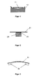
- the conductor preferably has a controlled range of motion in the holder, in the second case, it is firmly mounted and is contacted at the same time. Between the mounting elements, the band extends, preferably over a large part of its length, self-supporting. In the case of the edge mount concave mounting elements are preferably used, so that the main surfaces of the strip conductor can not come into planar contact with adjacent structures even when moving. The principle is shown in FIG. In this case, the band 11 can be installed by means of the mounting member 12 standing or lying or in any other position.
- the principle of contacting fixation is shown in Fig. 2.
- the strip conductor 21 is preferably connected via a flat metal bridging part 23 with a support part 24 which in turn is mounted on the fastening device (not shown). But it is also possible to use only a part 23, which is mounted directly on the fastening device.
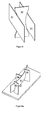
- the band must be able to expand during the heating, without bending or bending, especially during fixed installation. This is achieved by that it has degrees of freedom to move between each two fixed mounting elements. It is particularly advantageous if the band conductor is not straight, but always has a certain arc. Then the length expansion can be compensated by an elastic curvature: This principle is illustrated in FIG.
- All elements can be two-sided, so that a band is held on both sides. This is shown in Fig. 5 using the example of the tab 52. By the elements described so far, the tape is held only on one side. For two-sided support of the tape such elements must be arranged on both sides. Preferred arrangements are alternating ( Figure 6a) or paired arrangements ( Figure 6b), which pair may also be integrated into a single support as shown in Figure 6c to provide an eyelet. If the eyelet is not closed, but has an opening as in Fig. 6d and consists of sufficiently flexible material, the tape can be inserted from the side, which facilitates assembly. In the case of an annular holder or a closed loop, a narrow cut can be made, which allows the insertion of the strip conductor.
- This can be versatile to windings or use as insulation for cantilevered tape sections.
- elastic plastic spirals and round Kunststofflcämme as they are known as spines for brochures.
- plastic combs are advantageous because the band can be inserted laterally.
- the concave mounting elements as in FIGS. 4-7, only loosely comprise the band, then this still has a certain play and can shift in its longitudinal direction and change its direction to a limited degree in order to avoid the forces acting on the band. As a result, stronger deformations that would damage the band avoided.
- some versions are also suitable for a relatively fixed assembly of the tape. For the pairwise arrangement of the elements or the eyelet shape comes into question, the fit between tape and mounting elements must be adjusted so that the tape is indeed caught but not damaged. For this purpose, offers a resilient fit.
- the contact between band 21 and the bridging member 23 in Fig. 1 may preferably by brackets, low-melting solders, z. B. on indium, bismuth or tin base, press contacts, conductive silver paste or conductive adhesive, for example, on Epoxidharzbasis with Silberfiillung be prepared. Preference is given to press contacts, wherein as insert a film of soft metal, for. Indium, lead or copper, which is preferably wound around the tape. Also preferred are conductive adhesive, z. B. on epoxy resin with silver filling. Among epoxy resins, particularly preferred are cold-curing 2-component epoxy resins, since they have the best low-temperature properties.
- the support member 24 is normally fixedly connected to the bridging member 23 (eg, by gluing, screwing, riveting, soldering, or clamping). But it is also possible to provide a connection with game. Self-supporting bridging parts may also be considered if it is merely the bridging of a damaged area of the strip.
- FIGS. 8-12 Preferred embodiments of band assemblies for limiter components are exemplified in FIGS. 8-12. In all embodiments, the preferred minimum radius specified above must be taken into account.
- Fig. 8 shows z.
- a flat coil which is arranged with open lugs as mounting elements on a plate of insulating material as a fastening device.
- the flat coil shown here has the shape of a circular disk. Other examples are oval coils or square with rounded corners.
- Flat coils can be stacked on top of each other. In this case, they are preferably connected in such a way that the current flow takes place in opposite directions, in order to obtain the lowest possible intrinsic magnetic field and low inductance.
- Fig. 9 shows a single-layer cylindrical coil.
- the band lies on one side on tabs, which are attached to a tube.
- Cylindrical coils with stepped diameters can be placed inside each other, resulting in a multi-layer coil.
- the individual layers are preferably connected again in such a way that the current flow is opposite and the magnetic fields compensate each other.
- Figures 10a and 10b show single layer meanders in which the curves of the band are held by tabs attached to short half tubes.
- the tape is twisted on the self-supporting straight lines 200 each by 180 °. This is advantageous because then the front of the band is always in the inner curve and thus the superconductor is compressed.
- the twisting serves the mechanical stabilization of the band, in particular against vibrations. When twisting, the edges of the band are stretched and the central axis of the band is compressed. The maximum permissible deformation ⁇ max of the strip must not be exceeded.
- b is the bandwidth.
- the minimum pitch is about 350 mm, corresponding to a free length of 175 mm at 180 ° twist. This formula has proven itself in practice.
- Fig. 10c shows two layers of a meander stack.
- the posts are not drawn here. Between the two layers there is an unconstrained reversing loop. Thus, the front of the band always comes inward and also the current is in opposite directions in both layers. The latter, however, does not apply to the reverse loop.
- Fig. 10d For a flat and compact construction, the tape can also be wrapped around two posts. The result is shown in Fig. 11 a. By twisting, the windings can cross over without contact in the middle and the front is always inside. The magnetic fields compensate each other even better, and the isolation distances become larger if the crossovers occur only alternately, as shown in Fig. 11b. However, contrary to the figure, the crossing band sections should be twisted again so that the front of the band is always inside.
- yin-yang coil baseball coil
- adjacent strip sections 100 always have a spacing of more than 10%, preferably more than 40%, of the width of the strip conductor. This prevents the switching from the superconducting to the normal conducting state and the associated Warming the bubble development of the surrounding coolant leads to excessive deformation of the strip conductor.
- the specified values for the minimum distance ensure that the bubbles can escape essentially unhindered.
- FIG. 13 shows a preferred arrangement.
- three limiter components 85 consisting of flat coil stacks are shown here.
- Each component 85 is located in a chamber formed from partitions 86, which is preferably extended upward and there serves as a bubble chimney 87, which leads into a common gas container with cooling surface 88.
- the bubble chimneys must be chosen so long that flashovers in the gas are excluded.
- Connected to the gas tank is preferably still a pressure equalization tank (not shown).
- each chamber At the bottom of each chamber, a net 89 is stretched as a bubble barrier.
- the interconnection 90 of the components is located below one another in the bubble-free coolant with high dielectric strength below the chambers.
- the power supply lines 91 which are guided in extra sealed chambers and may consist of high-temperature superconducting material in the region of the cooling liquid in order not to cause unnecessary losses.
- the entire assembly is located in a fixed frame 92, which is drawn in Fig. 13, for example, as a cryostat and containing the coolant 93.
Landscapes
- Emergency Protection Circuit Devices (AREA)
- Containers, Films, And Cooling For Superconductive Devices (AREA)
- Control Of Electrical Variables (AREA)
Priority Applications (6)
| Application Number | Priority Date | Filing Date | Title |
|---|---|---|---|
| AT06004214T ATE435504T1 (de) | 2006-03-02 | 2006-03-02 | Resistiver strombegrenzer |
| DE502006004122T DE502006004122D1 (de) | 2006-03-02 | 2006-03-02 | Resistiver Strombegrenzer |
| EP06004214A EP1830419B1 (fr) | 2006-03-02 | 2006-03-02 | Limiteur de courant résistant |
| US11/396,920 US7760067B2 (en) | 2006-03-02 | 2006-04-04 | Resistive current limiter |
| JP2007080062A JP5190211B2 (ja) | 2006-03-02 | 2007-02-27 | 抵抗型限流器 |
| KR1020070020659A KR101297045B1 (ko) | 2006-03-02 | 2007-02-28 | 저항성 한류기 |
Applications Claiming Priority (1)
| Application Number | Priority Date | Filing Date | Title |
|---|---|---|---|
| EP06004214A EP1830419B1 (fr) | 2006-03-02 | 2006-03-02 | Limiteur de courant résistant |
Publications (2)
| Publication Number | Publication Date |
|---|---|
| EP1830419A1 true EP1830419A1 (fr) | 2007-09-05 |
| EP1830419B1 EP1830419B1 (fr) | 2009-07-01 |
Family
ID=37075932
Family Applications (1)
| Application Number | Title | Priority Date | Filing Date |
|---|---|---|---|
| EP06004214A Expired - Lifetime EP1830419B1 (fr) | 2006-03-02 | 2006-03-02 | Limiteur de courant résistant |
Country Status (6)
| Country | Link |
|---|---|
| US (1) | US7760067B2 (fr) |
| EP (1) | EP1830419B1 (fr) |
| JP (1) | JP5190211B2 (fr) |
| KR (1) | KR101297045B1 (fr) |
| AT (1) | ATE435504T1 (fr) |
| DE (1) | DE502006004122D1 (fr) |
Families Citing this family (10)
| Publication number | Priority date | Publication date | Assignee | Title |
|---|---|---|---|---|
| DE102006032973B3 (de) * | 2006-07-17 | 2008-02-14 | Siemens Ag | Supraleitende Strombegrenzereinrichtung von resistiven Typ mit Halteelement |
| JP5214154B2 (ja) * | 2007-01-19 | 2013-06-19 | 住友電気工業株式会社 | プリント配線板およびその製造方法 |
| US20090156409A1 (en) * | 2007-12-17 | 2009-06-18 | Superpower, Inc. | Fault current limiter incorporating a superconducting article |
| EP2472618A1 (fr) * | 2011-01-03 | 2012-07-04 | Nexans | Limiteur de courant de défaut à superconduction |
| EP2472532A1 (fr) * | 2011-01-04 | 2012-07-04 | Applied Superconductor Ltd. | Bobine, assemblage de bobine et limiteur de courant de défaut à superconduction |
| JP6117126B2 (ja) * | 2013-02-13 | 2017-04-19 | 古河電気工業株式会社 | 超電導限流器及び超電導限流器内の超電導素子の冷却方法 |
| JP5950951B2 (ja) * | 2013-02-13 | 2016-07-13 | 古河電気工業株式会社 | 超電導限流器及び超電導限流器内の超電導素子の冷却方法 |
| US10178799B2 (en) | 2013-02-13 | 2019-01-08 | Furukawa Electric Co., Ltd. | Superconducting fault current limiter and cooling method for superconducting element within superconducting fault current limiter |
| DE102016206573A1 (de) * | 2016-04-19 | 2017-10-19 | Siemens Aktiengesellschaft | Elektrische Spulenwicklung |
| US11032935B1 (en) * | 2019-12-10 | 2021-06-08 | Northrop Grumman Systems Corporation | Support structure for a flexible interconnect of a superconductor |
Citations (10)
| Publication number | Priority date | Publication date | Assignee | Title |
|---|---|---|---|---|
| EP0385485A2 (fr) * | 1989-03-03 | 1990-09-05 | Hitachi, Ltd. | Fil et bobine supraconductrice, à oxyde supraconducteur, et méthode pour leur fabrication |
| EP0444702A2 (fr) * | 1990-03-02 | 1991-09-04 | Hitachi, Ltd. | Enroulement supra-conducteur et son procédé de fabrication, supra-conducteur composite et son procédé de fabrication, et appareil supra-conducteur |
| EP0503448A2 (fr) * | 1991-03-09 | 1992-09-16 | ABBPATENT GmbH | Procédé pour la fabrication d'un limiter de courant supraconducteur et limiter de courant obtenu par le procédé |
| DE4434819C1 (de) * | 1994-09-29 | 1996-01-04 | Abb Research Ltd | Vorrichtung zur Strombegrenzung |
| EP1052707A2 (fr) * | 1999-05-10 | 2000-11-15 | Sumitomo Electric Industries, Ltd. | Procédé de fabrication d'un fil supraconducteur et support pour traitement thermique |
| DE19939066A1 (de) | 1999-08-18 | 2001-03-08 | Siemens Ag | Verfahren und zugehörige Anordnung zum Betrieb eines supraleitenden Strombegrenzers |
| EP1217708A1 (fr) * | 2000-12-21 | 2002-06-26 | Abb Research Ltd. | Dispositif supraconducteur |
| EP1217666A1 (fr) | 2000-12-21 | 2002-06-26 | Abb Research Ltd. | Limiteur de courant résistif |
| DE10142870A1 (de) * | 2001-08-27 | 2003-04-03 | Siemens Ag | Verfahren zum Erzeugen einer fortlaufenden Leiterbahnstruktur aus einem hochtemperatur-supraleitendem Werkstoff auf einem Träger, Vorrichtung zum Durchführen des Verfahrens und ein nach dem Verfahren hergestellter bandförmiger Träger |
| WO2004006345A2 (fr) * | 2002-07-03 | 2004-01-15 | Siemens Aktiengesellschaft | Structure de bande conductrice bifilaire d'un supraconducteur haute temperature pour limiter le courant |
Family Cites Families (11)
| Publication number | Priority date | Publication date | Assignee | Title |
|---|---|---|---|---|
| FR2094354A5 (fr) * | 1970-06-18 | 1972-02-04 | Commissariat Energie Atomique | |
| EP0454589B1 (fr) * | 1990-04-27 | 1995-11-08 | Railway Technical Research Institute | Interrupteur pour le contrôle de flux de courant dans des supraconducteurs |
| DE19720397A1 (de) | 1997-05-15 | 1999-04-01 | Magnet Motor Gmbh | Supraleitender Hochstromschalter |
| CA2315081A1 (fr) * | 1997-12-19 | 1999-07-01 | Gunter Ries | Structure supraconductrice en materiau supraconducteur a coefficient de temperature eleve, procede de production de cette structure et dispositif de limitation de courant dote d'une telle structure |
| US6275365B1 (en) | 1998-02-09 | 2001-08-14 | American Superconductor Corporation | Resistive fault current limiter |
| DE19827225C9 (de) | 1998-06-18 | 2007-01-11 | Siemens Ag | Resistiver Strombegrenzer |
| DE19836860A1 (de) | 1998-08-14 | 2000-02-17 | Abb Research Ltd | Elektrisch stabilisierter Dünnschicht-Hochtemperatursupraleiter sowie Verfahren zur Herstellung eines solchen Verfahrens |
| JP3892605B2 (ja) * | 1998-12-25 | 2007-03-14 | 株式会社東芝 | 限流素子用超電導コイル装置 |
| JP2000322957A (ja) * | 1999-05-10 | 2000-11-24 | Sumitomo Electric Ind Ltd | 超電導線材の製造方法 |
| DE10020943A1 (de) * | 2000-04-28 | 2001-10-31 | Oxeno Olefinchemie Gmbh | Verfahren zur Spaltung von Alkyl-tert.-alkylether zur Gewinnung von Iso-Olefinen und Alkanolen an sauren Katalysatoren |
| DE10225935C5 (de) | 2002-06-11 | 2011-10-06 | THEVA DüNNSCHICHTTECHNIK GMBH | Vorrichtung zum Leiten von Strom |
-
2006
- 2006-03-02 DE DE502006004122T patent/DE502006004122D1/de not_active Expired - Lifetime
- 2006-03-02 EP EP06004214A patent/EP1830419B1/fr not_active Expired - Lifetime
- 2006-03-02 AT AT06004214T patent/ATE435504T1/de active
- 2006-04-04 US US11/396,920 patent/US7760067B2/en not_active Expired - Fee Related
-
2007
- 2007-02-27 JP JP2007080062A patent/JP5190211B2/ja not_active Expired - Fee Related
- 2007-02-28 KR KR1020070020659A patent/KR101297045B1/ko not_active Expired - Fee Related
Patent Citations (10)
| Publication number | Priority date | Publication date | Assignee | Title |
|---|---|---|---|---|
| EP0385485A2 (fr) * | 1989-03-03 | 1990-09-05 | Hitachi, Ltd. | Fil et bobine supraconductrice, à oxyde supraconducteur, et méthode pour leur fabrication |
| EP0444702A2 (fr) * | 1990-03-02 | 1991-09-04 | Hitachi, Ltd. | Enroulement supra-conducteur et son procédé de fabrication, supra-conducteur composite et son procédé de fabrication, et appareil supra-conducteur |
| EP0503448A2 (fr) * | 1991-03-09 | 1992-09-16 | ABBPATENT GmbH | Procédé pour la fabrication d'un limiter de courant supraconducteur et limiter de courant obtenu par le procédé |
| DE4434819C1 (de) * | 1994-09-29 | 1996-01-04 | Abb Research Ltd | Vorrichtung zur Strombegrenzung |
| EP1052707A2 (fr) * | 1999-05-10 | 2000-11-15 | Sumitomo Electric Industries, Ltd. | Procédé de fabrication d'un fil supraconducteur et support pour traitement thermique |
| DE19939066A1 (de) | 1999-08-18 | 2001-03-08 | Siemens Ag | Verfahren und zugehörige Anordnung zum Betrieb eines supraleitenden Strombegrenzers |
| EP1217708A1 (fr) * | 2000-12-21 | 2002-06-26 | Abb Research Ltd. | Dispositif supraconducteur |
| EP1217666A1 (fr) | 2000-12-21 | 2002-06-26 | Abb Research Ltd. | Limiteur de courant résistif |
| DE10142870A1 (de) * | 2001-08-27 | 2003-04-03 | Siemens Ag | Verfahren zum Erzeugen einer fortlaufenden Leiterbahnstruktur aus einem hochtemperatur-supraleitendem Werkstoff auf einem Träger, Vorrichtung zum Durchführen des Verfahrens und ein nach dem Verfahren hergestellter bandförmiger Träger |
| WO2004006345A2 (fr) * | 2002-07-03 | 2004-01-15 | Siemens Aktiengesellschaft | Structure de bande conductrice bifilaire d'un supraconducteur haute temperature pour limiter le courant |
Non-Patent Citations (1)
| Title |
|---|
| NOE ET AL: "SUPRALEITENDE STROMBEGRENZER IN DER ENERGIETECHNIK", ELEKTRIE, VERLAG TECHNIK. BERLIN, DE, vol. 51, no. 11/12, 1997, pages 414 - 424, XP000869316, ISSN: 0013-5399 * |
Also Published As
| Publication number | Publication date |
|---|---|
| KR20070090785A (ko) | 2007-09-06 |
| JP2007294922A (ja) | 2007-11-08 |
| DE502006004122D1 (de) | 2009-08-13 |
| ATE435504T1 (de) | 2009-07-15 |
| JP5190211B2 (ja) | 2013-04-24 |
| EP1830419B1 (fr) | 2009-07-01 |
| US7760067B2 (en) | 2010-07-20 |
| US20070205857A1 (en) | 2007-09-06 |
| KR101297045B1 (ko) | 2013-08-14 |
Similar Documents
| Publication | Publication Date | Title |
|---|---|---|
| DE102008029722B3 (de) | Leiteranordnung für ein resistives Schaltelement mit wenigstens zwei Leiterverbünden aus supraleitenden Leiterbändern | |
| DE3887090T2 (de) | Supraleitender strombegrenzender Apparat. | |
| EP2228806B1 (fr) | Limiteur de courant | |
| EP1830419B1 (fr) | Limiteur de courant résistant | |
| DE1640750B1 (de) | Supraleitendes wechselstromkabel | |
| EP1797599A1 (fr) | Limiteur de courant supraconducteur de type resistif comportant une piste supraconductrice a tc elevee en forme de bande | |
| DE69511718T2 (de) | Regelung des kühlmittelflusses in einem kernreaktor | |
| DE1279182B (de) | Supraleitungsspule | |
| EP1217708A1 (fr) | Dispositif supraconducteur | |
| DE202025106148U1 (de) | Batteriebaugruppe und Batteriepack | |
| DE1962704A1 (de) | Supraleitfaehige Schaltstrecke fuer Starkstrom | |
| EP1301933A1 (fr) | Dispositif supraconducteur comportant une unite de limitation de courant inductive realisee a l'aide d'un materiau supraconducteur hote tc | |
| DE69308592T2 (de) | Gasgekühlte durchführung in kryotanks für anwendungen bei supraleitern | |
| EP0055804B1 (fr) | Supraconducteur stabilisé en forme de câble pour champs alternatifs | |
| EP2041808A1 (fr) | Dispositif limiteur de courant supraconducteur du type résistif avec élément d'arrêt | |
| DE2748479A1 (de) | Uebergangsstueck zwischen einem supraleiter und einem normalleiter | |
| EP0972295A2 (fr) | Ensemble pour la commutation d'installations d'energie | |
| DE102009013318A1 (de) | Supraleitender Strombegrenzer mit Magnetfeldtriggerung | |
| DE1564701C3 (de) | Supraleitende Wicklung mit Metallbrücken | |
| DE102006032972B3 (de) | Supraleitende Strombegrenzereinrichtung vom resistiven Typ mit mehrteiligem Halteelement | |
| EP1217666A1 (fr) | Limiteur de courant résistif | |
| DE3200420A1 (de) | Klemmenleiste | |
| WO2012041886A1 (fr) | Système et procédé pour la mise en contact électrique de conducteurs électriques dans des bobines | |
| CH673724A5 (fr) | ||
| EP1282142B1 (fr) | Système d'enroulement électrique |
Legal Events
| Date | Code | Title | Description |
|---|---|---|---|
| PUAI | Public reference made under article 153(3) epc to a published international application that has entered the european phase |
Free format text: ORIGINAL CODE: 0009012 |
|
| AK | Designated contracting states |
Kind code of ref document: A1 Designated state(s): AT BE BG CH CY CZ DE DK EE ES FI FR GB GR HU IE IS IT LI LT LU LV MC NL PL PT RO SE SI SK TR |
|
| AX | Request for extension of the european patent |
Extension state: AL BA HR MK YU |
|
| 17P | Request for examination filed |
Effective date: 20080303 |
|
| 17Q | First examination report despatched |
Effective date: 20080408 |
|
| AKX | Designation fees paid |
Designated state(s): AT BE BG CH CY CZ DE DK EE ES FI FR GB GR HU IE IS IT LI LT LU LV MC NL PL PT RO SE SI SK TR |
|
| GRAP | Despatch of communication of intention to grant a patent |
Free format text: ORIGINAL CODE: EPIDOSNIGR1 |
|
| GRAS | Grant fee paid |
Free format text: ORIGINAL CODE: EPIDOSNIGR3 |
|
| GRAA | (expected) grant |
Free format text: ORIGINAL CODE: 0009210 |
|
| AK | Designated contracting states |
Kind code of ref document: B1 Designated state(s): AT BE BG CH CY CZ DE DK EE ES FI FR GB GR HU IE IS IT LI LT LU LV MC NL PL PT RO SE SI SK TR |
|
| REG | Reference to a national code |
Ref country code: GB Ref legal event code: FG4D Free format text: NOT ENGLISH |
|
| REG | Reference to a national code |
Ref country code: CH Ref legal event code: EP |
|
| REG | Reference to a national code |
Ref country code: IE Ref legal event code: FG4D |
|
| REF | Corresponds to: |
Ref document number: 502006004122 Country of ref document: DE Date of ref document: 20090813 Kind code of ref document: P |
|
| REG | Reference to a national code |
Ref country code: CH Ref legal event code: NV Representative=s name: HEPP WENGER RYFFEL AG |
|
| PG25 | Lapsed in a contracting state [announced via postgrant information from national office to epo] |
Ref country code: SI Free format text: LAPSE BECAUSE OF FAILURE TO SUBMIT A TRANSLATION OF THE DESCRIPTION OR TO PAY THE FEE WITHIN THE PRESCRIBED TIME-LIMIT Effective date: 20090701 |
|
| NLV1 | Nl: lapsed or annulled due to failure to fulfill the requirements of art. 29p and 29m of the patents act | ||
| PG25 | Lapsed in a contracting state [announced via postgrant information from national office to epo] |
Ref country code: FI Free format text: LAPSE BECAUSE OF FAILURE TO SUBMIT A TRANSLATION OF THE DESCRIPTION OR TO PAY THE FEE WITHIN THE PRESCRIBED TIME-LIMIT Effective date: 20090701 Ref country code: SE Free format text: LAPSE BECAUSE OF FAILURE TO SUBMIT A TRANSLATION OF THE DESCRIPTION OR TO PAY THE FEE WITHIN THE PRESCRIBED TIME-LIMIT Effective date: 20090701 Ref country code: LT Free format text: LAPSE BECAUSE OF FAILURE TO SUBMIT A TRANSLATION OF THE DESCRIPTION OR TO PAY THE FEE WITHIN THE PRESCRIBED TIME-LIMIT Effective date: 20090701 Ref country code: ES Free format text: LAPSE BECAUSE OF FAILURE TO SUBMIT A TRANSLATION OF THE DESCRIPTION OR TO PAY THE FEE WITHIN THE PRESCRIBED TIME-LIMIT Effective date: 20091012 Ref country code: EE Free format text: LAPSE BECAUSE OF FAILURE TO SUBMIT A TRANSLATION OF THE DESCRIPTION OR TO PAY THE FEE WITHIN THE PRESCRIBED TIME-LIMIT Effective date: 20090701 Ref country code: IS Free format text: LAPSE BECAUSE OF FAILURE TO SUBMIT A TRANSLATION OF THE DESCRIPTION OR TO PAY THE FEE WITHIN THE PRESCRIBED TIME-LIMIT Effective date: 20091101 |
|
| REG | Reference to a national code |
Ref country code: IE Ref legal event code: FD4D |
|
| PG25 | Lapsed in a contracting state [announced via postgrant information from national office to epo] |
Ref country code: NL Free format text: LAPSE BECAUSE OF FAILURE TO SUBMIT A TRANSLATION OF THE DESCRIPTION OR TO PAY THE FEE WITHIN THE PRESCRIBED TIME-LIMIT Effective date: 20090701 Ref country code: PL Free format text: LAPSE BECAUSE OF FAILURE TO SUBMIT A TRANSLATION OF THE DESCRIPTION OR TO PAY THE FEE WITHIN THE PRESCRIBED TIME-LIMIT Effective date: 20090701 Ref country code: LV Free format text: LAPSE BECAUSE OF FAILURE TO SUBMIT A TRANSLATION OF THE DESCRIPTION OR TO PAY THE FEE WITHIN THE PRESCRIBED TIME-LIMIT Effective date: 20090701 |
|
| PG25 | Lapsed in a contracting state [announced via postgrant information from national office to epo] |
Ref country code: PT Free format text: LAPSE BECAUSE OF FAILURE TO SUBMIT A TRANSLATION OF THE DESCRIPTION OR TO PAY THE FEE WITHIN THE PRESCRIBED TIME-LIMIT Effective date: 20091102 Ref country code: BG Free format text: LAPSE BECAUSE OF FAILURE TO SUBMIT A TRANSLATION OF THE DESCRIPTION OR TO PAY THE FEE WITHIN THE PRESCRIBED TIME-LIMIT Effective date: 20091001 |
|
| PG25 | Lapsed in a contracting state [announced via postgrant information from national office to epo] |
Ref country code: RO Free format text: LAPSE BECAUSE OF FAILURE TO SUBMIT A TRANSLATION OF THE DESCRIPTION OR TO PAY THE FEE WITHIN THE PRESCRIBED TIME-LIMIT Effective date: 20090701 Ref country code: CZ Free format text: LAPSE BECAUSE OF FAILURE TO SUBMIT A TRANSLATION OF THE DESCRIPTION OR TO PAY THE FEE WITHIN THE PRESCRIBED TIME-LIMIT Effective date: 20090701 Ref country code: IE Free format text: LAPSE BECAUSE OF FAILURE TO SUBMIT A TRANSLATION OF THE DESCRIPTION OR TO PAY THE FEE WITHIN THE PRESCRIBED TIME-LIMIT Effective date: 20090701 Ref country code: DK Free format text: LAPSE BECAUSE OF FAILURE TO SUBMIT A TRANSLATION OF THE DESCRIPTION OR TO PAY THE FEE WITHIN THE PRESCRIBED TIME-LIMIT Effective date: 20090701 |
|
| PLBE | No opposition filed within time limit |
Free format text: ORIGINAL CODE: 0009261 |
|
| STAA | Information on the status of an ep patent application or granted ep patent |
Free format text: STATUS: NO OPPOSITION FILED WITHIN TIME LIMIT |
|
| PG25 | Lapsed in a contracting state [announced via postgrant information from national office to epo] |
Ref country code: SK Free format text: LAPSE BECAUSE OF FAILURE TO SUBMIT A TRANSLATION OF THE DESCRIPTION OR TO PAY THE FEE WITHIN THE PRESCRIBED TIME-LIMIT Effective date: 20090701 |
|
| 26N | No opposition filed |
Effective date: 20100406 |
|
| BERE | Be: lapsed |
Owner name: THEVA DUNNSCHICHTTECHNIK G.M.B.H. Effective date: 20100331 |
|
| PG25 | Lapsed in a contracting state [announced via postgrant information from national office to epo] |
Ref country code: GR Free format text: LAPSE BECAUSE OF FAILURE TO SUBMIT A TRANSLATION OF THE DESCRIPTION OR TO PAY THE FEE WITHIN THE PRESCRIBED TIME-LIMIT Effective date: 20091002 Ref country code: MC Free format text: LAPSE BECAUSE OF NON-PAYMENT OF DUE FEES Effective date: 20100331 |
|
| PG25 | Lapsed in a contracting state [announced via postgrant information from national office to epo] |
Ref country code: BE Free format text: LAPSE BECAUSE OF NON-PAYMENT OF DUE FEES Effective date: 20100331 |
|
| PG25 | Lapsed in a contracting state [announced via postgrant information from national office to epo] |
Ref country code: IT Free format text: LAPSE BECAUSE OF FAILURE TO SUBMIT A TRANSLATION OF THE DESCRIPTION OR TO PAY THE FEE WITHIN THE PRESCRIBED TIME-LIMIT Effective date: 20090701 |
|
| PG25 | Lapsed in a contracting state [announced via postgrant information from national office to epo] |
Ref country code: CY Free format text: LAPSE BECAUSE OF FAILURE TO SUBMIT A TRANSLATION OF THE DESCRIPTION OR TO PAY THE FEE WITHIN THE PRESCRIBED TIME-LIMIT Effective date: 20090701 |
|
| PG25 | Lapsed in a contracting state [announced via postgrant information from national office to epo] |
Ref country code: LU Free format text: LAPSE BECAUSE OF NON-PAYMENT OF DUE FEES Effective date: 20100302 Ref country code: HU Free format text: LAPSE BECAUSE OF FAILURE TO SUBMIT A TRANSLATION OF THE DESCRIPTION OR TO PAY THE FEE WITHIN THE PRESCRIBED TIME-LIMIT Effective date: 20100102 |
|
| PG25 | Lapsed in a contracting state [announced via postgrant information from national office to epo] |
Ref country code: TR Free format text: LAPSE BECAUSE OF FAILURE TO SUBMIT A TRANSLATION OF THE DESCRIPTION OR TO PAY THE FEE WITHIN THE PRESCRIBED TIME-LIMIT Effective date: 20090701 |
|
| REG | Reference to a national code |
Ref country code: AT Ref legal event code: MM01 Ref document number: 435504 Country of ref document: AT Kind code of ref document: T Effective date: 20110302 |
|
| PG25 | Lapsed in a contracting state [announced via postgrant information from national office to epo] |
Ref country code: AT Free format text: LAPSE BECAUSE OF NON-PAYMENT OF DUE FEES Effective date: 20110302 |
|
| PGFP | Annual fee paid to national office [announced via postgrant information from national office to epo] |
Ref country code: DE Payment date: 20140321 Year of fee payment: 9 Ref country code: CH Payment date: 20140324 Year of fee payment: 9 |
|
| PGFP | Annual fee paid to national office [announced via postgrant information from national office to epo] |
Ref country code: FR Payment date: 20140319 Year of fee payment: 9 |
|
| PGFP | Annual fee paid to national office [announced via postgrant information from national office to epo] |
Ref country code: GB Payment date: 20140324 Year of fee payment: 9 |
|
| REG | Reference to a national code |
Ref country code: DE Ref legal event code: R119 Ref document number: 502006004122 Country of ref document: DE |
|
| REG | Reference to a national code |
Ref country code: CH Ref legal event code: PL |
|
| GBPC | Gb: european patent ceased through non-payment of renewal fee |
Effective date: 20150302 |
|
| REG | Reference to a national code |
Ref country code: FR Ref legal event code: ST Effective date: 20151130 |
|
| PG25 | Lapsed in a contracting state [announced via postgrant information from national office to epo] |
Ref country code: LI Free format text: LAPSE BECAUSE OF NON-PAYMENT OF DUE FEES Effective date: 20150331 Ref country code: GB Free format text: LAPSE BECAUSE OF NON-PAYMENT OF DUE FEES Effective date: 20150302 Ref country code: CH Free format text: LAPSE BECAUSE OF NON-PAYMENT OF DUE FEES Effective date: 20150331 Ref country code: DE Free format text: LAPSE BECAUSE OF NON-PAYMENT OF DUE FEES Effective date: 20151001 |
|
| PG25 | Lapsed in a contracting state [announced via postgrant information from national office to epo] |
Ref country code: FR Free format text: LAPSE BECAUSE OF NON-PAYMENT OF DUE FEES Effective date: 20150331 |