EP1834543A1 - Load bearing system - Google Patents
Load bearing system Download PDFInfo
- Publication number
- EP1834543A1 EP1834543A1 EP20060004821 EP06004821A EP1834543A1 EP 1834543 A1 EP1834543 A1 EP 1834543A1 EP 20060004821 EP20060004821 EP 20060004821 EP 06004821 A EP06004821 A EP 06004821A EP 1834543 A1 EP1834543 A1 EP 1834543A1
- Authority
- EP
- European Patent Office
- Prior art keywords
- strap
- load bearing
- woven
- woven portion
- warp yarns
- Prior art date
- Legal status (The legal status is an assumption and is not a legal conclusion. Google has not performed a legal analysis and makes no representation as to the accuracy of the status listed.)
- Granted
Links
Images



Classifications
-
- A—HUMAN NECESSITIES
- A45—HAND OR TRAVELLING ARTICLES
- A45F—TRAVELLING OR CAMP EQUIPMENT: SACKS OR PACKS CARRIED ON THE BODY
- A45F3/00—Travelling or camp articles; Sacks or packs carried on the body
- A45F3/12—Shoulder-pads
-
- D—TEXTILES; PAPER
- D03—WEAVING
- D03D—WOVEN FABRICS; METHODS OF WEAVING; LOOMS
- D03D15/00—Woven fabrics characterised by the material, structure or properties of the fibres, filaments, yarns, threads or other warp or weft elements used
- D03D15/50—Woven fabrics characterised by the material, structure or properties of the fibres, filaments, yarns, threads or other warp or weft elements used characterised by the properties of the yarns or threads
- D03D15/587—Woven fabrics characterised by the material, structure or properties of the fibres, filaments, yarns, threads or other warp or weft elements used characterised by the properties of the yarns or threads adhesive; fusible
-
- D—TEXTILES; PAPER
- D03—WEAVING
- D03D—WOVEN FABRICS; METHODS OF WEAVING; LOOMS
- D03D25/00—Woven fabrics not otherwise provided for
-
- A—HUMAN NECESSITIES
- A62—LIFE-SAVING; FIRE-FIGHTING
- A62B—DEVICES, APPARATUS OR METHODS FOR LIFE-SAVING
- A62B35/00—Safety belts or body harnesses; Similar equipment for limiting displacement of the human body, especially in case of sudden changes of motion
- A62B35/0006—Harnesses; Accessories therefor
- A62B35/0025—Details and accessories
-
- Y—GENERAL TAGGING OF NEW TECHNOLOGICAL DEVELOPMENTS; GENERAL TAGGING OF CROSS-SECTIONAL TECHNOLOGIES SPANNING OVER SEVERAL SECTIONS OF THE IPC; TECHNICAL SUBJECTS COVERED BY FORMER USPC CROSS-REFERENCE ART COLLECTIONS [XRACs] AND DIGESTS
- Y10—TECHNICAL SUBJECTS COVERED BY FORMER USPC
- Y10T—TECHNICAL SUBJECTS COVERED BY FORMER US CLASSIFICATION
- Y10T442/00—Fabric [woven, knitted, or nonwoven textile or cloth, etc.]
- Y10T442/10—Scrim [e.g., open net or mesh, gauze, loose or open weave or knit, etc.]
- Y10T442/102—Woven scrim
Definitions
- the invention relates to a load bearing system comprising a load bearing textile strap.
- the invention will find useful applications anywhere where a load needs to be spread along a contacting surface.
- Such useful applications will include objects which are supposed to come in contact with a portion of the body of the user of such object, such as: climbing harnesses, backpack shoulder straps, backpack hip belts, ski pole straps, medical slings, car seat belts, bag carrying straps, etc....
- a cushion pad may be provided adjacent the strap, so that the cushion pad is interposed between the strap and the user's body in order to avoid direct contact.
- the cushion pad is sometimes wider that the load bearing strap, but, usually by only a small amount.
- the cushion pad being basically soft, it has a significant load spreading effect only very close to the edges of the strap. Therefore, the load is not properly spread and may result in too much contact pressure on the body, causing undesirable effects.
- the invention may also be useful in other categories of applications, like for example in industrial lifting slings. Indeed, in such applications, it may also be desirable to increase the load spreading effect between the load bearing system and the object which it comes in contact with.
- variable width textile straps In order to achieve better spreading of the load, it is known to use variable width textile straps. Such straps are woven in a specific way at predefined positions along their length, most of the time by modifying the weaving parameters in a specific section of the strap. Typically, such techniques allow to increase the width of the strap at those specific predefined locations up to double the nominal width of the strap, but not more. Such techniques increase the production cost of the strap and they show no flexibility: once the strap is woven, the location, shape and measurements of the portions of increased width cannot be adjusted to each specific application.
- variable width straps do achieve a load spreading effect, but it is limited by the maximum width increasing ratio.
- Other constraints include having to weave a specific strap for each individual application.
- the invention provides for a load bearing system comprising a load bearing textile strap, wherein said strap comprises a woven portion having warp yarns extending along a longitudinal direction of the strap interlaced with at least one weft yarn, wherein said woven portion of the strap has a first width, wherein said strap has a non-woven portion comprising only at least a part of said warp yarns, and wherein, in said non-woven portion, said warp yarns are spread transversally so as to spread over a second width greater that said first width of said woven portion.
- a woven strap 10 Basically it comprises a series of warp textile yarns 12 which all extend substantially parallel one to another along the longitudinal direction of the strap.
- at least one weft textile yarn 14 is provided which is interlaced with the warp yarns 12, in that it extends transversally back and forth across the width of the strap, passing over some of the warp yarns and under other warp yarns.
- diverse weaving patterns can be used (plain weave, twill weave, satin weave, etc%), each of them having all sorts of possible variations and elaborations.
- the strap could also be woven with several weft yarns. In each case though, the weft yarn(s) 14 is (are) continuous and, when it reaches the edge of the series of warp yarn, it turns back in the opposite transverse direction, again being interlaced with the warp yarns 12.
- FIGmatic aspect of Figure 1 does not show that, in a woven strap, the warp and weft yarns are preferably tightly woven so that in fact non void space is visible between the yarns.
- a strap can be made which seemingly exhibits several superimposed layers of warp yarns, the layers being interconnected or not by the weft yarn. It also know to have a special weaving/knitting of the weft and warp yarns along the edges of the strap, mainly in order to provide an additional locking effect of the weft yarn on the edge warp yarns. Such locking ensures that the strap does not unravel totally if the weft yarn brakes at one point of the strap.
- warp and weft yarns appear to be of the same nature and size, but it is of course common to use different warp and weft yarns, and also to use different warp yarns along the width of the strap, for example using stronger warp yarns along the edges of the strap.
- the woven portion of the strap had a fist width. Although that first width could vary along the length of the woven portion (as known in the prior art), the first width is substantially constant along the length of the non-woven portion.
- a strap 10 having a portion where the weft yarn is absent, that is a non-woven portion 16.
- the non-woven portion is an intermediate portion of the strap between two woven portions 18, 20.
- the non woven portion16 of the strap has only warp yarns 12 extending along the longitudinal direction of the strap 10. Those warp yarns 12 are continuous with the warp yarns 12 of the two woven portions 18, 20 adjacent the non-woven portion. In the example shown, all the warp yarns of both woven portions are continuous through the non-woven portion. Nevertheless, it could be chosen that only a portion of the warp yarns 12 of those woven portions 18, 20 are continued through the non woven portion 16.
- Such non-woven portion 16 could be made simply by interrupting the weaving process, namely by interrupting the interlacing of the weft yarn(s) with the warp yarns on the weaving loom, while letting the warp yarns advance through the loom. Therefore, after a first upstream woven portion 18 has been woven, the weaving process would be interrupted for a period of time corresponding to the time necessary for the desired length of the non-woven portion to advance through the loom. Then, the weaving process would resume in order to weave the adjacent downstream woven portion 20. A strap 10 with a built-in non-woven intermediate portion 16 could therefore be directly produced in such way.
- FIG. 5 and 6 is shown an alternative and very simple method to make a non-woven portion 16 in an initially continuously woven strap as shown in Figure 1.
- the idea is simply to remove the weft yarn(s) 14 in the desired portion of the strap. In order to do so, it is sufficient to cut the weft yarn(s) 14 along one of the edges of the woven strap 10.
- a weft yarn 14 is cut a two of its consecutive turn back locations at the edge of the strap 10
- the weft yarn forms, between the two cut-outs, something like a "U pin” with only the branches interlaced with the warp yarns. That "U pin” is virtually not locked any more to the warp yarn and can be easily pulled out.
- the locking weave/knit usually involves only one or a few warp yarns along each edge of the strap, and for commodity, it may be simpler to cut also those warp yarns at each of the longitudinal ends of the desired non-woven portions and to remove them together with the weft yam(s).
- the main advantage of this process is that it is possible to use almost any standard strap, so that the strap can be sourced in great quantities for a variety of applications. Indeed, with a given standard strap, it is very easy to adjust the length and position of the non-woven portion(s) relative to the length and position of the woven portions, keeping full flexibility in the choice of the base strap depending on the application. To the contrary, a ready-made strap with built-in non-woven portions will not exhibit such flexibility.
- the cutting of the weft yarn(s) may be done manually, as indicated in Figure 5, for example with scissors or with a blade, or it can be done with a specific tool, for example a die-cut, or even with a machine like a laser cutting machine.
- Manual operations will be of course more flexible, the exact length and position of the non woven portion being easily determined by the precise location of the cutting. Operations done with a specific tool or machines will be more productive, while requiring some preparation.
- the warp fibres of the non woven-portion of the strap can be spread transversally and maintained transversally spread apart.
- One method would be to make a series of transverse stitches to stitch down the warp yarns 12 on a support surface.
- Such support surface could be any kind of textile material, of laminate material, of film, etc...
- the warp yarns 12 may be very effectively maintained in their spread apart configuration by adhesive bonding.
- the yarns be affixed on a support surface by welding, for example ultrasonic or radio-frequency welding. But, in most cases, the adhesive bonding preferably will be achieved through the use of adhesive materials such as glues or glue-containing compounds.
- adhesive materials such as glues or glue-containing compounds.
- glues can be used, such as, for example, polyurethane based glues. Those glues can be in the form of self-standing films or in liquid form. They can be thermo-activated glues, e.g., hot-melt glues.
- a glue-containing compound may be for example made of two or more films of hot-melt adhesive, possibly of different compositions to adapt to the specific materials of the warp yarns on one side and of a support surface on the other side.
- the gluing compound could also possibly have an interfacial layer between two adhesive films.
- the interfacial layer could for example be a fabric layer or a foam layer.
- the adhesive bonding is achieved though the use of a self-standing film of thermo-activated polyurethane glue 22.
- the film is for example pre-cut to a desired shape (which here corresponds to the shape of the non-woven portion 16 of the strap 10 and its spread apart warp yarns 12) and simply heat pressed on the strap.
- the glue will flow very intimately around each yarn and secure each yarn very solidly. Indeed, contrary to a tightly woven web where the tight interlacing might prevent the glue from perfectly bonding to the fibres (unless a perfect match of temperature, glue flow rate and glue quantity is achieved), it will be relatively easily to secure a perfect bonding of the yarns.
- non-woven portion 16 be sandwiched between two films of hot-melt glue 22.
- the film(s) of glue has (have) a length greater than the length of the non-woven portion in order to cover not only the non-woven portion 16 but also the neighbouring parts 17, 19 of the woven portions 18, 20.
- the film of glue will therefore not only maintain the warp yarns 12 in a spread apart configuration, but will also prevent the terminal transversal edges of the woven portions 18, 20 from fraying.
- the strap therefore exhibits a load spreading portion of having an increased second width compared to the first width of the woven portion.
- the load spreading portion is made without compromising the amount of load that the strap can withstand since the warp yarns 12, which bear most of the load, are continuous through both woven portions 18, 20 and through the non-woven portion 16.
- the strap and its load spreading portion can be totally or partially encased in a flexible casing or envelope, made for example of two sheets of textile material joined along their edges.
- the load spreading portions of the strap will preferably be glued inside the casing.
- a cushioning layer Adjacent the load spreading portion of the strap, it is possible to provide a cushioning layer, for example a foam layer.
- the cushioning layer may be glued onto the load spreading portion.
- the cushioning layer may for example be contained within the casing.
- the embodiment described above has a non-woven portion in an intermediate location between two woven portions of the strap.
- Figure 7 is shown the case where the non-woven portion is an end portion of the strap, which end portion is to be connected to a support surface 24 in order to transfer the load to said support surface 24.
- Such an embodiment can be used for example when connecting a load bearing strap to a backpack waist-belt, etc.
- the warp yarns 12 of the non-woven portions have free ends (not connected to another woven portion), so that they can be spread angularly apart as in a fan.
- this fanned end portion can be glued on the support surface 24 via any of the techniques described above (for example by using a thermo-activated sheet of glue, or simply by stitching), and it can also be covered by a covering layer 26, which itself can be glued on with another sheet of glue 22.
- FIG 8 is shown an exemplary application of the invention, with the load bearing system being integrated in a climbing harness 30.
- the climbing harness 30 has for example a waist belt 23 and two leg loops 34.
- the waist belt 32 and the two legs loops 34 each have a rear comfort part 36, 38 of greater width which is intended to transfer most of the contact pressure between the harness 30 and the corresponding parts of the user's body, respectively the lumbar part of the back and the back of the thighs.
- a securing ring 40 is secured on the front part of the waist belt and a link strap 42 connects the two legs loops 34 while passing through the securing ring 42.
- the waist belt 32 comprises a load bearing system according to the invention.
- a load bearing textile strap 10 encircles the waist of the user and is closed on itself in an adjustable manner through an adjustment buckle 44.
- the strap 10 is a woven strap having a non woven portion 16.
- the non woven portion 16 is located in the rear comfort zone 36 of the waist belt 32, in order to give it its enlarged width.
- the non woven portion 16 of the strap is encased in a textile casing 46 (partially cut-out in the drawing to show the non woven portion of the strap).
- the front part of the strap, and especially the connecting zone where the adjustment buckle 44 is located, is made up of two woven portions 18 of the strap 10.
- the two leg loops 34 are constructed in a similar way with a load bearing strap 10 which is closed on itself (here in a non-adjustable manner, for example through adequate sewing of the two woven extremities of the strap), the strap having a non-woven back portion 16 (also encased in a supple casing 46) intended to come in contact with the back of the user's thighs.
- a climbing harness constructed as above is extremely light in weight while remaining comfortable to wear, thanks to the load spreading effect of the non-woven portion of the strap.
Landscapes
- Engineering & Computer Science (AREA)
- Textile Engineering (AREA)
- Woven Fabrics (AREA)
- Sliding-Contact Bearings (AREA)
- Support Of The Bearing (AREA)
- Separation By Low-Temperature Treatments (AREA)
- Transition And Organic Metals Composition Catalysts For Addition Polymerization (AREA)
- Vehicle Body Suspensions (AREA)
Abstract
Description
- The invention relates to a load bearing system comprising a load bearing textile strap.
- The invention will find useful applications anywhere where a load needs to be spread along a contacting surface. Such useful applications will include objects which are supposed to come in contact with a portion of the body of the user of such object, such as: climbing harnesses, backpack shoulder straps, backpack hip belts, ski pole straps, medical slings, car seat belts, bag carrying straps, etc....
- Currently, in such applications, a cushion pad may be provided adjacent the strap, so that the cushion pad is interposed between the strap and the user's body in order to avoid direct contact. The cushion pad is sometimes wider that the load bearing strap, but, usually by only a small amount. Moreover, the cushion pad being basically soft, it has a significant load spreading effect only very close to the edges of the strap. Therefore, the load is not properly spread and may result in too much contact pressure on the body, causing undesirable effects.
- The invention may also be useful in other categories of applications, like for example in industrial lifting slings. Indeed, in such applications, it may also be desirable to increase the load spreading effect between the load bearing system and the object which it comes in contact with.
- In order to achieve better spreading of the load, it is known to use variable width textile straps. Such straps are woven in a specific way at predefined positions along their length, most of the time by modifying the weaving parameters in a specific section of the strap. Typically, such techniques allow to increase the width of the strap at those specific predefined locations up to double the nominal width of the strap, but not more. Such techniques increase the production cost of the strap and they show no flexibility: once the strap is woven, the location, shape and measurements of the portions of increased width cannot be adjusted to each specific application.
- Such variable width straps do achieve a load spreading effect, but it is limited by the maximum width increasing ratio. Other constraints include having to weave a specific strap for each individual application.
- It is therefore an objective of the invention to provide a new construction for a load bearing systems which achieves a desired load spreading effect in an easy, flexible, low-cost and effective way.
- In view of this objective, the invention provides for a load bearing system comprising a load bearing textile strap, wherein said strap comprises a woven portion having warp yarns extending along a longitudinal direction of the strap interlaced with at least one weft yarn, wherein said woven portion of the strap has a first width, wherein said strap has a non-woven portion comprising only at least a part of said warp yarns, and wherein, in said non-woven portion, said warp yarns are spread transversally so as to spread over a second width greater that said first width of said woven portion.
- Other aspects of the invention will be set forth in the following detailed specification which refers to the appended drawings in which:
- Figure 1 is a schematic view of one example of a conventional woven strap;
- Figure 2 is a schematic view of the strap of Figure 1 where, in an intermediate portion of the strap, the weft yarn(s) has (have) been removed, forming an intermediate non-woven portion;
- Figure 3 is a schematic view of the strap of Figure 2 where, in the intermediate non-woven portion, the warp yarns have been spread transversally;
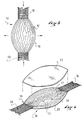
- Figure 4 is a schematic perspective view of the strap of Figure 3 showing how the warp yarns of said non-woven portion may be adhesively bonded on a support surface;
- Figure 5 and 6 are schematic drawings showing a simple and economical process for removing the weft yarn(s) in a portion of a conventional woven strap;
- Figure 7 is a schematic perspective view of another embodiment of the invention where the non woven portion is an end position of the strap, and;
- Figure 8 is a schematic perspective view of a climbing harness equipped with a load-bearing system according to the invention.
- On figure 1 is shown very schematically a
woven strap 10. Basically it comprises a series ofwarp textile yarns 12 which all extend substantially parallel one to another along the longitudinal direction of the strap. As in any woven textile, at least oneweft textile yarn 14 is provided which is interlaced with thewarp yarns 12, in that it extends transversally back and forth across the width of the strap, passing over some of the warp yarns and under other warp yarns. It is well known that diverse weaving patterns can be used (plain weave, twill weave, satin weave, etc...), each of them having all sorts of possible variations and elaborations. The strap could also be woven with several weft yarns. In each case though, the weft yarn(s) 14 is (are) continuous and, when it reaches the edge of the series of warp yarn, it turns back in the opposite transverse direction, again being interlaced with thewarp yarns 12. - The diagrammatic aspect of Figure 1 does not show that, in a woven strap, the warp and weft yarns are preferably tightly woven so that in fact non void space is visible between the yarns. Moreover, with certain weaving patterns, a strap can be made which seemingly exhibits several superimposed layers of warp yarns, the layers being interconnected or not by the weft yarn. It also know to have a special weaving/knitting of the weft and warp yarns along the edges of the strap, mainly in order to provide an additional locking effect of the weft yarn on the edge warp yarns. Such locking ensures that the strap does not unravel totally if the weft yarn brakes at one point of the strap. In the drawings, the warp and weft yarns appear to be of the same nature and size, but it is of course common to use different warp and weft yarns, and also to use different warp yarns along the width of the strap, for example using stronger warp yarns along the edges of the strap.
- The woven portion of the strap had a fist width. Although that first width could vary along the length of the woven portion (as known in the prior art), the first width is substantially constant along the length of the non-woven portion.
- According to one aspect of the invention, it is provided a
strap 10 having a portion where the weft yarn is absent, that is a non-wovenportion 16. - In the example shown on Figure 2, the non-woven portion is an intermediate portion of the strap between two
woven portions warp yarns 12 extending along the longitudinal direction of thestrap 10. Thosewarp yarns 12 are continuous with thewarp yarns 12 of the twowoven portions warp yarns 12 of thosewoven portions non woven portion 16. - Such
non-woven portion 16 could be made simply by interrupting the weaving process, namely by interrupting the interlacing of the weft yarn(s) with the warp yarns on the weaving loom, while letting the warp yarns advance through the loom. Therefore, after a first upstreamwoven portion 18 has been woven, the weaving process would be interrupted for a period of time corresponding to the time necessary for the desired length of the non-woven portion to advance through the loom. Then, the weaving process would resume in order to weave the adjacentdownstream woven portion 20. Astrap 10 with a built-in non-wovenintermediate portion 16 could therefore be directly produced in such way. - In figures 5 and 6 is shown an alternative and very simple method to make a
non-woven portion 16 in an initially continuously woven strap as shown in Figure 1. The idea is simply to remove the weft yarn(s) 14 in the desired portion of the strap. In order to do so, it is sufficient to cut the weft yarn(s) 14 along one of the edges of thewoven strap 10. As shown on figures 5 and 6, if aweft yarn 14 is cut a two of its consecutive turn back locations at the edge of thestrap 10, then the weft yarn forms, between the two cut-outs, something like a "U pin" with only the branches interlaced with the warp yarns. That "U pin" is virtually not locked any more to the warp yarn and can be easily pulled out. If the strap has been woven with an additional special locking effect along the edges of the strap (as discussed above), the locking weave/knit usually involves only one or a few warp yarns along each edge of the strap, and for commodity, it may be simpler to cut also those warp yarns at each of the longitudinal ends of the desired non-woven portions and to remove them together with the weft yam(s). - The main advantage of this process is that it is possible to use almost any standard strap, so that the strap can be sourced in great quantities for a variety of applications. Indeed, with a given standard strap, it is very easy to adjust the length and position of the non-woven portion(s) relative to the length and position of the woven portions, keeping full flexibility in the choice of the base strap depending on the application. To the contrary, a ready-made strap with built-in non-woven portions will not exhibit such flexibility.
- The cutting of the weft yarn(s) may be done manually, as indicated in Figure 5, for example with scissors or with a blade, or it can be done with a specific tool, for example a die-cut, or even with a machine like a laser cutting machine. Manual operations will be of course more flexible, the exact length and position of the non woven portion being easily determined by the precise location of the cutting. Operations done with a specific tool or machines will be more productive, while requiring some preparation.
- As can be seen in Figures 3 and 4, the warp fibres of the non woven-portion of the strap can be spread transversally and maintained transversally spread apart.
- Various techniques can be used to maintain the warp yarns in the spread apart configuration.
- One method would be to make a series of transverse stitches to stitch down the
warp yarns 12 on a support surface. Such support surface could be any kind of textile material, of laminate material, of film, etc... - But, according to an optional aspect of the invention, the
warp yarns 12 may be very effectively maintained in their spread apart configuration by adhesive bonding. - Depending on the materials making up the yarns, different adhesive bonding techniques can be used. It is within the scope of the invention that, if the materials are compatible, one can envision that the yarns be affixed on a support surface by welding, for example ultrasonic or radio-frequency welding. But, in most cases, the adhesive bonding preferably will be achieved through the use of adhesive materials such as glues or glue-containing compounds. Many types of glues can be used, such as, for example, polyurethane based glues. Those glues can be in the form of self-standing films or in liquid form. They can be thermo-activated glues, e.g., hot-melt glues. A glue-containing compound may be for example made of two or more films of hot-melt adhesive, possibly of different compositions to adapt to the specific materials of the warp yarns on one side and of a support surface on the other side. The gluing compound could also possibly have an interfacial layer between two adhesive films. The interfacial layer could for example be a fabric layer or a foam layer.
- In the example shown, the adhesive bonding is achieved though the use of a self-standing film of thermo-activated
polyurethane glue 22. The film is for example pre-cut to a desired shape (which here corresponds to the shape of thenon-woven portion 16 of thestrap 10 and its spread apart warp yarns 12) and simply heat pressed on the strap. In doing so, the glue will flow very intimately around each yarn and secure each yarn very solidly. Indeed, contrary to a tightly woven web where the tight interlacing might prevent the glue from perfectly bonding to the fibres (unless a perfect match of temperature, glue flow rate and glue quantity is achieved), it will be relatively easily to secure a perfect bonding of the yarns. - As shown in Figure 4, it is possible to provide that the
non-woven portion 16 be sandwiched between two films of hot-melt glue 22. - In any case, it is desirable that the film(s) of glue has (have) a length greater than the length of the non-woven portion in order to cover not only the
non-woven portion 16 but also the neighbouringparts woven portions warp yarns 12 in a spread apart configuration, but will also prevent the terminal transversal edges of thewoven portions - The strap therefore exhibits a load spreading portion of having an increased second width compared to the first width of the woven portion. The load spreading portion is made without compromising the amount of load that the strap can withstand since the
warp yarns 12, which bear most of the load, are continuous through both wovenportions non-woven portion 16. - The strap and its load spreading portion can be totally or partially encased in a flexible casing or envelope, made for example of two sheets of textile material joined along their edges. The load spreading portions of the strap will preferably be glued inside the casing.
- Adjacent the load spreading portion of the strap, it is possible to provide a cushioning layer, for example a foam layer. The cushioning layer may be glued onto the load spreading portion. In case the load spreading portion is encased in a casing, the cushioning layer may for example be contained within the casing.
- The embodiment described above has a non-woven portion in an intermediate location between two woven portions of the strap.
- In Figure 7 is shown the case where the non-woven portion is an end portion of the strap, which end portion is to be connected to a
support surface 24 in order to transfer the load to saidsupport surface 24. - Such an embodiment can be used for example when connecting a load bearing strap to a backpack waist-belt, etc.
- Here, it can be seen that the
warp yarns 12 of the non-woven portions have free ends (not connected to another woven portion), so that they can be spread angularly apart as in a fan. As discussed above, this fanned end portion can be glued on thesupport surface 24 via any of the techniques described above (for example by using a thermo-activated sheet of glue, or simply by stitching), and it can also be covered by acovering layer 26, which itself can be glued on with another sheet ofglue 22. - In Figure 8 is shown an exemplary application of the invention, with the load bearing system being integrated in a climbing
harness 30. The climbingharness 30 has for example a waist belt 23 and twoleg loops 34. Thewaist belt 32 and the twolegs loops 34 each have arear comfort part harness 30 and the corresponding parts of the user's body, respectively the lumbar part of the back and the back of the thighs. - A securing
ring 40 is secured on the front part of the waist belt and alink strap 42 connects the twolegs loops 34 while passing through the securingring 42. - As can be seen on figure 8, the
waist belt 32 comprises a load bearing system according to the invention. A load bearingtextile strap 10 encircles the waist of the user and is closed on itself in an adjustable manner through anadjustment buckle 44. According to the invention, thestrap 10 is a woven strap having a non wovenportion 16. Advantageously, the non wovenportion 16 is located in therear comfort zone 36 of thewaist belt 32, in order to give it its enlarged width. In the example shown, the non wovenportion 16 of the strap is encased in a textile casing 46 (partially cut-out in the drawing to show the non woven portion of the strap). The front part of the strap, and especially the connecting zone where theadjustment buckle 44 is located, is made up of twowoven portions 18 of thestrap 10. - The two
leg loops 34 are constructed in a similar way with aload bearing strap 10 which is closed on itself (here in a non-adjustable manner, for example through adequate sewing of the two woven extremities of the strap), the strap having a non-woven back portion 16 (also encased in a supple casing 46) intended to come in contact with the back of the user's thighs. - A climbing harness constructed as above is extremely light in weight while remaining comfortable to wear, thanks to the load spreading effect of the non-woven portion of the strap.
- Of course many variations can be devised in the use of the load bearing system according to the invention in a climbing harness. For example, only the waist belt or only the leg loops could be built using a load bearing system according to the invention.
- Other uses of the invention are contemplated for making various articles such as: backpack shoulder straps and hip belts, industrial lifting slings, ski pole straps, gear slings, gun straps, musical instrument straps, medical slings, etc...
Claims (12)
- A load bearing system comprising a load bearing textile strap (10), wherein said strap comprises a woven portion having warp yarns (12) extending along a longitudinal direction of the strap interlaced with at least one weft yarn (14), wherein said woven portion (18) of the strap has a first width, wherein said strap has a non-woven portion (16) comprising only at least a part of said warp yarns (12), and wherein, in said non-woven portion, said warp yarns (12) are spread transversally so as to spread over a second width greater that said first width of said woven portion (18).
- A load bearing system according to claim 1, wherein the warp yarns (12) of said non-woven portion (16) are maintained in a spread configuration by adhesive bonding.
- A load bearing system according to claim 2, wherein the warp yarns (12) are of said non-woven portion (16) are adhesively bonded on a support surface (24).
- A load bearing element according to claim 2 or 3, wherein the warp yarns (12) are of said non-woven portion (16) are adhesively bonded on a film of glue.
- A load bearing system according to claim 1, wherein the warp yarns of said non-woven portion are maintained in a spread configuration by stitching on a support surface.
- A load bearing system according to any preceding claim, wherein said non-woven portion is an end portion of the strap.
- A load bearing system according to any of claims 1 to 5, wherein said non-woven portion (16) is an intermediate portion of the strap (10) between two woven portions (18) having warp yarns (12) extending along a longitudinal direction of the strap interlaced with at least one weft yarn (14).
- A load bearing system according to any preceding claim, wherein said non-woven portion (16) is encased in a flexible casing.
- A load bearing system according to any preceding claim, wherein a cushioning pad is placed adjacent said non-woven portion of the strap.
- A load bearing system according to claim 9, wherein the cushioning pad is adhesively bonded to the non-woven portion of the strap.
- A climbing harness incorporating a load bearing system according to any of the preceding claims.
- A backpack comprising at least one should strap and/or one waist belt incorporating a load bearing system according to any of the preceding claims.
Priority Applications (4)
| Application Number | Priority Date | Filing Date | Title |
|---|---|---|---|
| AT06004821T ATE435602T1 (en) | 2006-03-09 | 2006-03-09 | LOAD CARRYING SYSTEM |
| EP20060004821 EP1834543B1 (en) | 2006-03-09 | 2006-03-09 | Load bearing system |
| DE200660007676 DE602006007676D1 (en) | 2006-03-09 | 2006-03-09 | Load carrying system |
| US11/452,318 US7743885B2 (en) | 2006-03-09 | 2006-06-14 | Load bearing system, and an article including such load bearing system |
Applications Claiming Priority (1)
| Application Number | Priority Date | Filing Date | Title |
|---|---|---|---|
| EP20060004821 EP1834543B1 (en) | 2006-03-09 | 2006-03-09 | Load bearing system |
Publications (2)
| Publication Number | Publication Date |
|---|---|
| EP1834543A1 true EP1834543A1 (en) | 2007-09-19 |
| EP1834543B1 EP1834543B1 (en) | 2009-07-08 |
Family
ID=36655170
Family Applications (1)
| Application Number | Title | Priority Date | Filing Date |
|---|---|---|---|
| EP20060004821 Expired - Lifetime EP1834543B1 (en) | 2006-03-09 | 2006-03-09 | Load bearing system |
Country Status (4)
| Country | Link |
|---|---|
| US (1) | US7743885B2 (en) |
| EP (1) | EP1834543B1 (en) |
| AT (1) | ATE435602T1 (en) |
| DE (1) | DE602006007676D1 (en) |
Cited By (11)
| Publication number | Priority date | Publication date | Assignee | Title |
|---|---|---|---|---|
| WO2011107676A1 (en) | 2010-03-04 | 2011-09-09 | Zedel | Tie-in harness having a force distributor, and method for manufacturing same |
| EP2383018A1 (en) | 2010-04-28 | 2011-11-02 | Mammut Sports Group AG | Brace and method for manufacturing the same |
| WO2012131346A3 (en) * | 2011-03-25 | 2013-07-18 | Latchways Plc | Harness safety system |
| FR3007994A1 (en) * | 2013-07-05 | 2015-01-09 | Beal Ets | HARNESS AND SAFETY BRACKETS |
| DE102013011435A1 (en) * | 2013-07-10 | 2015-01-15 | Edelrid Gmbh & Co. Kg | Safety belt for persons |
| EP3006090A1 (en) * | 2014-10-06 | 2016-04-13 | Black Diamond Equipment AG | Improved harness and load bearing systems |
| FR3037811A1 (en) * | 2015-06-29 | 2016-12-30 | Zedel | STRAP FORMING BELT AND / OR PAIR OF THROUGHING HARNESS THRUTS, AND ATTACHING HARNESS |
| EP3549639A1 (en) * | 2018-04-05 | 2019-10-09 | Zedel | Harness |
| WO2021224555A1 (en) | 2020-05-07 | 2021-11-11 | Blue Ice Europe | Fall arrest and load distribution harness and a method for manufacturing said harness |
| EP4458427A1 (en) | 2023-05-05 | 2024-11-06 | Zedel | Roping harness and method for manufacturing such a harness |
| FR3148378A1 (en) | 2023-05-05 | 2024-11-08 | Zedel | RIDING HARNESS AND METHOD OF MANUFACTURING SUCH A HARNESS |
Families Citing this family (26)
| Publication number | Priority date | Publication date | Assignee | Title |
|---|---|---|---|---|
| US7900036B2 (en) * | 2006-12-18 | 2011-03-01 | International Business Machines Corporation | System and method for implementing boot/recovery on a data processing sysem |
| EP1970102B1 (en) * | 2007-03-13 | 2016-10-19 | Amer Sports Canada Inc. | Securing ring and corresponding manufacturing process |
| US7762932B2 (en) | 2007-09-17 | 2010-07-27 | Fitness Anywhere, Inc. | Inelastic exercise device having a limited range |
| US7963005B2 (en) * | 2008-04-03 | 2011-06-21 | Knox Gregory H C | Method and apparatus for fastening objects to an elastic surface |
| US9056656B2 (en) * | 2008-07-18 | 2015-06-16 | Thomas W. Fields | Mooring loop |
| US8038584B1 (en) * | 2008-09-26 | 2011-10-18 | Hal Pruessner | Method and apparatus for practicing yoga in and around trees |
| USD685950S1 (en) | 2011-08-02 | 2013-07-09 | Larry Clyde Sparkes | Leg support harness |
| GB201118171D0 (en) * | 2011-10-21 | 2011-12-07 | Elliott Daniel | Improvements relating to protective chaps |
| DE102012000182B4 (en) * | 2012-01-09 | 2021-07-08 | Edelrid Gmbh & Co. Kg | Seat belt for people |
| KR101237196B1 (en) | 2012-02-09 | 2013-02-25 | 김정석 | A safety belt fabric using a safety belt for high place work |
| CN103263737B (en) * | 2013-05-16 | 2015-09-02 | 国家电网公司 | Pole operation anti-fall device |
| US10143892B2 (en) | 2014-04-12 | 2018-12-04 | Black Diamond Equipment, Ltd. | Cam stem system |
| US20150360062A1 (en) * | 2014-06-11 | 2015-12-17 | Edward Anthony Oliver | Personal Positioning Strap System |
| FR3026649B1 (en) * | 2014-10-07 | 2019-05-17 | Zedel | CONNECTING HARNESS |
| US10463916B2 (en) * | 2016-07-01 | 2019-11-05 | Erick Matthew Davidson | Active camming device |
| CN106863930B (en) * | 2017-04-06 | 2019-03-15 | 特大纺织制品(深圳)有限公司 | A kind of knitmesh and its safe back belt |
| FR3067942B1 (en) * | 2017-06-26 | 2019-08-23 | Zedel | CONNECTING HARNESS |
| US10933260B2 (en) * | 2018-09-08 | 2021-03-02 | Black Diamond Equipment, Ltd. | Mesh harness systems |
| US20200108294A1 (en) * | 2018-10-08 | 2020-04-09 | Black Diamond Equipment, Ltd. | Belay Loop |
| DE102019121171B4 (en) * | 2019-08-06 | 2021-04-29 | Skylotec Gmbh | Belt to be placed on a person to be secured with a webbing bridge |
| US11950685B2 (en) | 2020-10-05 | 2024-04-09 | Stumpworx Llc | Pressure-relieving flexural load bearing strap and method for manufacturing same |
| US11597476B2 (en) | 2020-08-25 | 2023-03-07 | Thomas W. Fields | Controlled failure point for a rope or mooring loop and method of use thereof |
| US12440356B2 (en) | 2020-10-05 | 2025-10-14 | Stumpworx Llc | Pressure-relieving flexural load-bearing strap and related systems and methods |
| US20220266073A1 (en) * | 2021-02-25 | 2022-08-25 | Thomas Calvin Dalziel | Sling Climbing Harness |
| US12604971B2 (en) | 2022-09-22 | 2026-04-21 | Amer Sports Canada Inc. | Attachment system having splayed strands |
| USD1093748S1 (en) | 2023-04-03 | 2025-09-16 | Amer Sports Canada Inc. | Leg loop of a harness |
Citations (3)
| Publication number | Priority date | Publication date | Assignee | Title |
|---|---|---|---|---|
| WO1987005342A1 (en) * | 1986-03-06 | 1987-09-11 | Jukka Reijonen | A method of manufacturing wide/narrow webbing |
| FR2829002A1 (en) * | 2001-08-30 | 2003-03-07 | Rossignol Sa | IMPROVEMENT FOR BACKPACK CARRYING SYSTEM |
| US20040262080A1 (en) * | 2003-06-25 | 2004-12-30 | Reynolds Richard G | Full body harness for fall arrest utilizing variable-width webbing |
Family Cites Families (40)
| Publication number | Priority date | Publication date | Assignee | Title |
|---|---|---|---|---|
| US129928A (en) * | 1872-07-30 | Improvement in belt-splices | ||
| US703568A (en) * | 1901-09-07 | 1902-07-01 | Henry Jacques Gaisman | Waist-belt. |
| US726670A (en) * | 1902-11-01 | 1903-04-28 | Otto E Geisel | Method of joining the ends of woven belts. |
| US949519A (en) * | 1909-03-15 | 1910-02-15 | Charles O L Cardell | Belt-fastener. |
| US1328406A (en) * | 1916-05-15 | 1920-01-20 | Albert T Van Alstyn | Supporter |
| US1261118A (en) * | 1916-06-15 | 1918-04-02 | Otto E Geisel | Method for joining woven belts. |
| US1255594A (en) * | 1917-05-10 | 1918-02-05 | Otto E Geisel | Power-transmission belt. |
| US1477084A (en) * | 1918-03-22 | 1923-12-11 | Manning J Smith | Belt |
| US1373457A (en) * | 1919-10-03 | 1921-04-05 | Manning J Smith | Power-transmission belt |
| US1770742A (en) * | 1929-09-19 | 1930-07-15 | Moore Fab Co | Curvilinear garter |
| US1903406A (en) * | 1931-01-08 | 1933-04-04 | George F Putvin | Seam for drier felts and method of making same |
| US2122623A (en) * | 1937-02-17 | 1938-07-05 | Paul M Rogers | Method of manufacturing mops and the like |
| US2494646A (en) * | 1944-08-02 | 1950-01-17 | Celanese Corp | Woven fabric |
| DE1165354B (en) * | 1960-12-31 | 1964-03-12 | Franz Clouth Rheinische Gummiw | Connection point for conveyor belts or drive belts made of rubber or rubber substitutes with wire rope inserts in the longitudinal direction |
| US3122755A (en) * | 1962-05-23 | 1964-03-03 | Rosen Fred | Hula skirt belt |
| US3316017A (en) * | 1965-07-28 | 1967-04-25 | Francis M Knight | Safety seat belt |
| US3481807A (en) * | 1965-08-11 | 1969-12-02 | Mitsubishi Belt Kk | Method of joining the ends of a conveyor belt reinforced with steel strands |
| US3415703A (en) * | 1966-03-18 | 1968-12-10 | Giffen Burgess Corp | Process for face-seaming carpeting |
| US3487871A (en) * | 1966-09-07 | 1970-01-06 | Mitsubashi Belt Kk | Method of joining conveyer belts having steel cords embedded therein |
| US3713174A (en) * | 1967-07-20 | 1973-01-30 | J Boussac | Method of articles of clothing |
| US3444957A (en) * | 1967-12-13 | 1969-05-20 | Rose Mfg Co | Shock absorber for safety belt |
| US4015035A (en) * | 1972-08-10 | 1977-03-29 | Lockheed Aircraft Corporation | Method of forming fiber-reinforced epoxy composite joints, and product thereof |
| US3937407A (en) * | 1974-05-24 | 1976-02-10 | The United States Of America As Represented By The Secretary Of The Navy | Multiple strap shock absorber |
| US4177522A (en) * | 1977-11-25 | 1979-12-11 | Auburn Parker K | Survival belt |
| US4298648A (en) * | 1979-02-28 | 1981-11-03 | Celanese Corporation | Belting fabric |
| US4370784A (en) * | 1979-02-28 | 1983-02-01 | Celanese Corporation | Belting fabric |
| US4427107A (en) * | 1979-05-19 | 1984-01-24 | J. H. Fenner & Co. Ltd. | Belting |
| US4325999A (en) * | 1979-11-23 | 1982-04-20 | Hitco | Bias fabric |
| CH669328A5 (en) * | 1986-09-18 | 1989-03-15 | Vitapharm Basel Ag | |
| DE3714088A1 (en) * | 1987-04-28 | 1988-12-01 | Messerschmitt Boelkow Blohm | STRAP FOR A RESTRAINT SYSTEM IN A VEHICLE, PARTICULARLY IN AN AIRCRAFT |
| US5091243A (en) * | 1989-04-04 | 1992-02-25 | Springs Industries, Inc. | Fire barrier fabric |
| US5507682A (en) * | 1992-12-14 | 1996-04-16 | Triumph International Aktiengesellschaft | Shoulder strap for ladies undergarments |
| US5467802A (en) * | 1994-01-21 | 1995-11-21 | The Bentley-Harris Manufacturing Company | Woven sleeve with integral lacing cord |
| WO2001026738A1 (en) * | 1999-10-14 | 2001-04-19 | Rose Manufacturing Company | Lanyard with integral fall arrest energy absorber |
| US6328080B1 (en) * | 2000-09-27 | 2001-12-11 | Federal-Mogul Systems Protection Group, Inc. | Woven sleeve with integral monofilament fasteners |
| GB0029039D0 (en) * | 2000-11-29 | 2001-01-10 | Uniline Safety Systems Ltd | Termination arrangement for a horizontal lifeline cable |
| CA2570211A1 (en) | 2003-06-18 | 2004-12-23 | Arc'teryx Equipment Inc. | Interdigitating quick release web fastener |
| ITPG20030037A1 (en) * | 2003-07-03 | 2003-10-01 | Lanzi Srl | TEXTILE BRAID OF RIGID FIBER AND CONSTITUENT ELASTIC FIBER FOUND ELESTIC ORIGINATING ONE OR MORE RIGID SLOTS. |
| US7354876B2 (en) * | 2003-07-09 | 2008-04-08 | Saint-Gobain Technical Fabrics Canada Ltd. | Fabric reinforcement and cementitious boards faced with same |
| US20050189169A1 (en) * | 2004-03-01 | 2005-09-01 | Hajime Tanaka | Shock absorbing lanyards |
-
2006
- 2006-03-09 EP EP20060004821 patent/EP1834543B1/en not_active Expired - Lifetime
- 2006-03-09 AT AT06004821T patent/ATE435602T1/en active
- 2006-03-09 DE DE200660007676 patent/DE602006007676D1/en not_active Expired - Lifetime
- 2006-06-14 US US11/452,318 patent/US7743885B2/en active Active
Patent Citations (3)
| Publication number | Priority date | Publication date | Assignee | Title |
|---|---|---|---|---|
| WO1987005342A1 (en) * | 1986-03-06 | 1987-09-11 | Jukka Reijonen | A method of manufacturing wide/narrow webbing |
| FR2829002A1 (en) * | 2001-08-30 | 2003-03-07 | Rossignol Sa | IMPROVEMENT FOR BACKPACK CARRYING SYSTEM |
| US20040262080A1 (en) * | 2003-06-25 | 2004-12-30 | Reynolds Richard G | Full body harness for fall arrest utilizing variable-width webbing |
Cited By (25)
| Publication number | Priority date | Publication date | Assignee | Title |
|---|---|---|---|---|
| FR2956980A1 (en) * | 2010-03-04 | 2011-09-09 | Zedel | EFFORTS DISTRIBUTOR ENHANCEMENT HARNESS, AND METHOD FOR MANUFACTURING THE SAME |
| WO2011107676A1 (en) | 2010-03-04 | 2011-09-09 | Zedel | Tie-in harness having a force distributor, and method for manufacturing same |
| EP2383018A1 (en) | 2010-04-28 | 2011-11-02 | Mammut Sports Group AG | Brace and method for manufacturing the same |
| WO2012131346A3 (en) * | 2011-03-25 | 2013-07-18 | Latchways Plc | Harness safety system |
| GB2489417B (en) * | 2011-03-25 | 2016-06-22 | Latchways Plc | Harness safety system |
| FR3007994A1 (en) * | 2013-07-05 | 2015-01-09 | Beal Ets | HARNESS AND SAFETY BRACKETS |
| DE102013011435B4 (en) | 2013-07-10 | 2022-06-23 | Edelrid Gmbh & Co. Kg | Seat belt for people |
| DE102013011435A1 (en) * | 2013-07-10 | 2015-01-15 | Edelrid Gmbh & Co. Kg | Safety belt for persons |
| EP3006090A1 (en) * | 2014-10-06 | 2016-04-13 | Black Diamond Equipment AG | Improved harness and load bearing systems |
| US10143865B2 (en) | 2014-10-06 | 2018-12-04 | Black Diamond Equipment, Ltd. | Harness and load bearing systems |
| US10675490B2 (en) | 2015-06-29 | 2020-06-09 | Zedel | Strap forming a belt and/or pair of thigh straps of a roping harness, and roping harness |
| EP3111998A1 (en) * | 2015-06-29 | 2017-01-04 | Zedel | Strap forming a belt and/or a pair of leg loops of a safety harness, and safety harness |
| FR3037811A1 (en) * | 2015-06-29 | 2016-12-30 | Zedel | STRAP FORMING BELT AND / OR PAIR OF THROUGHING HARNESS THRUTS, AND ATTACHING HARNESS |
| CN106267741A (en) * | 2015-06-29 | 2017-01-04 | 齐德公司 | Form the band of cable-styled harness and/or the bandage of a pair thigh bandage and cable-styled harness |
| US11311755B2 (en) | 2018-04-05 | 2022-04-26 | Zedel | Harness |
| FR3079755A1 (en) * | 2018-04-05 | 2019-10-11 | Zedel | HARNESS |
| EP3549639A1 (en) * | 2018-04-05 | 2019-10-09 | Zedel | Harness |
| WO2021224555A1 (en) | 2020-05-07 | 2021-11-11 | Blue Ice Europe | Fall arrest and load distribution harness and a method for manufacturing said harness |
| FR3109890A1 (en) | 2020-05-07 | 2021-11-12 | Blue Ice Europe | Fall arrest and force distributor harness and a method of manufacturing said harness |
| CN115551602A (en) * | 2020-05-07 | 2022-12-30 | 蓝冰欧洲公司 | Fall arrest and load spreader safety belt and method for manufacturing same |
| CN115551602B (en) * | 2020-05-07 | 2024-04-16 | 蓝冰欧洲公司 | Fall arrest and load distributor safety belt and method for manufacturing the same |
| EP4458427A1 (en) | 2023-05-05 | 2024-11-06 | Zedel | Roping harness and method for manufacturing such a harness |
| FR3148377A1 (en) | 2023-05-05 | 2024-11-08 | Zedel | RIGGING HARNESS AND METHOD OF MANUFACTURING SUCH RIGGING HARNESS |
| FR3148378A1 (en) | 2023-05-05 | 2024-11-08 | Zedel | RIDING HARNESS AND METHOD OF MANUFACTURING SUCH A HARNESS |
| EP4461379A1 (en) | 2023-05-05 | 2024-11-13 | Zedel | Roping harness and method for manufacturing such a harness |
Also Published As
| Publication number | Publication date |
|---|---|
| DE602006007676D1 (en) | 2009-08-20 |
| ATE435602T1 (en) | 2009-07-15 |
| EP1834543B1 (en) | 2009-07-08 |
| US7743885B2 (en) | 2010-06-29 |
| US20070209869A1 (en) | 2007-09-13 |
Similar Documents
| Publication | Publication Date | Title |
|---|---|---|
| EP1834543B1 (en) | Load bearing system | |
| US6156001A (en) | Garment or sanitary protection made of an elastic fabric directly engageable by "velcro" fasteners | |
| US11317666B2 (en) | Waistband for article of apparel featuring cord and embroidery tunnel | |
| US20020035747A1 (en) | Briefs for supporting an absorbent article | |
| KR20230080498A (en) | Travel pillow with anchoring features | |
| AU8172387A (en) | Cushioned strap | |
| EP4014774A1 (en) | Brassiere assembly | |
| CA2319832A1 (en) | Inflatable belt strap | |
| CN101180102A (en) | Equipped with a safety harness with improved straps | |
| US20110159781A1 (en) | Curved tape and women's clothing with cup employing curved tape | |
| US20250250724A1 (en) | Harness component | |
| EP2329732A2 (en) | Size fitting device and wearable article including said device | |
| JP2018175607A (en) | Piggyback belt | |
| FR3007994A1 (en) | HARNESS AND SAFETY BRACKETS | |
| JP4705980B2 (en) | Pelvic correction belt | |
| EP3001928B1 (en) | A rucksack | |
| US20240366975A1 (en) | Roping harness and method for manufacturing one such roping harness | |
| US1147135A (en) | Woven strap. | |
| JP7449566B2 (en) | Waist or pelvic belt | |
| JP4360973B2 (en) | Clothing with cup and back cloth | |
| CN222930194U (en) | Rope harness | |
| US20250249297A1 (en) | Harness component | |
| US20250249298A1 (en) | Harness component | |
| CN220221094U (en) | Split waistband | |
| JP2013221230A (en) | Fabric material |
Legal Events
| Date | Code | Title | Description |
|---|---|---|---|
| PUAI | Public reference made under article 153(3) epc to a published international application that has entered the european phase |
Free format text: ORIGINAL CODE: 0009012 |
|
| 17P | Request for examination filed |
Effective date: 20060309 |
|
| AK | Designated contracting states |
Kind code of ref document: A1 Designated state(s): AT BE BG CH CY CZ DE DK EE ES FI FR GB GR HU IE IS IT LI LT LU LV MC NL PL PT RO SE SI SK TR |
|
| AX | Request for extension of the european patent |
Extension state: AL BA HR MK YU |
|
| AKX | Designation fees paid |
Designated state(s): AT BE BG CH CY CZ DE DK EE ES FI FR GB GR HU IE IS IT LI LT LU LV MC NL PL PT RO SE SI SK TR |
|
| 17Q | First examination report despatched |
Effective date: 20080509 |
|
| GRAP | Despatch of communication of intention to grant a patent |
Free format text: ORIGINAL CODE: EPIDOSNIGR1 |
|
| GRAS | Grant fee paid |
Free format text: ORIGINAL CODE: EPIDOSNIGR3 |
|
| GRAA | (expected) grant |
Free format text: ORIGINAL CODE: 0009210 |
|
| AK | Designated contracting states |
Kind code of ref document: B1 Designated state(s): AT BE BG CH CY CZ DE DK EE ES FI FR GB GR HU IE IS IT LI LT LU LV MC NL PL PT RO SE SI SK TR |
|
| REG | Reference to a national code |
Ref country code: GB Ref legal event code: FG4D |
|
| REG | Reference to a national code |
Ref country code: CH Ref legal event code: EP |
|
| REG | Reference to a national code |
Ref country code: IE Ref legal event code: FG4D |
|
| REF | Corresponds to: |
Ref document number: 602006007676 Country of ref document: DE Date of ref document: 20090820 Kind code of ref document: P |
|
| PG25 | Lapsed in a contracting state [announced via postgrant information from national office to epo] |
Ref country code: SI Free format text: LAPSE BECAUSE OF FAILURE TO SUBMIT A TRANSLATION OF THE DESCRIPTION OR TO PAY THE FEE WITHIN THE PRESCRIBED TIME-LIMIT Effective date: 20090708 |
|
| NLV1 | Nl: lapsed or annulled due to failure to fulfill the requirements of art. 29p and 29m of the patents act | ||
| PG25 | Lapsed in a contracting state [announced via postgrant information from national office to epo] |
Ref country code: IS Free format text: LAPSE BECAUSE OF FAILURE TO SUBMIT A TRANSLATION OF THE DESCRIPTION OR TO PAY THE FEE WITHIN THE PRESCRIBED TIME-LIMIT Effective date: 20091108 Ref country code: FI Free format text: LAPSE BECAUSE OF FAILURE TO SUBMIT A TRANSLATION OF THE DESCRIPTION OR TO PAY THE FEE WITHIN THE PRESCRIBED TIME-LIMIT Effective date: 20090708 Ref country code: ES Free format text: LAPSE BECAUSE OF FAILURE TO SUBMIT A TRANSLATION OF THE DESCRIPTION OR TO PAY THE FEE WITHIN THE PRESCRIBED TIME-LIMIT Effective date: 20091019 Ref country code: LT Free format text: LAPSE BECAUSE OF FAILURE TO SUBMIT A TRANSLATION OF THE DESCRIPTION OR TO PAY THE FEE WITHIN THE PRESCRIBED TIME-LIMIT Effective date: 20090708 |
|
| PG25 | Lapsed in a contracting state [announced via postgrant information from national office to epo] |
Ref country code: PL Free format text: LAPSE BECAUSE OF FAILURE TO SUBMIT A TRANSLATION OF THE DESCRIPTION OR TO PAY THE FEE WITHIN THE PRESCRIBED TIME-LIMIT Effective date: 20090708 Ref country code: NL Free format text: LAPSE BECAUSE OF FAILURE TO SUBMIT A TRANSLATION OF THE DESCRIPTION OR TO PAY THE FEE WITHIN THE PRESCRIBED TIME-LIMIT Effective date: 20090708 Ref country code: LV Free format text: LAPSE BECAUSE OF FAILURE TO SUBMIT A TRANSLATION OF THE DESCRIPTION OR TO PAY THE FEE WITHIN THE PRESCRIBED TIME-LIMIT Effective date: 20090708 |
|
| PG25 | Lapsed in a contracting state [announced via postgrant information from national office to epo] |
Ref country code: BG Free format text: LAPSE BECAUSE OF FAILURE TO SUBMIT A TRANSLATION OF THE DESCRIPTION OR TO PAY THE FEE WITHIN THE PRESCRIBED TIME-LIMIT Effective date: 20091008 Ref country code: PT Free format text: LAPSE BECAUSE OF FAILURE TO SUBMIT A TRANSLATION OF THE DESCRIPTION OR TO PAY THE FEE WITHIN THE PRESCRIBED TIME-LIMIT Effective date: 20091109 |
|
| PG25 | Lapsed in a contracting state [announced via postgrant information from national office to epo] |
Ref country code: RO Free format text: LAPSE BECAUSE OF FAILURE TO SUBMIT A TRANSLATION OF THE DESCRIPTION OR TO PAY THE FEE WITHIN THE PRESCRIBED TIME-LIMIT Effective date: 20090708 Ref country code: EE Free format text: LAPSE BECAUSE OF FAILURE TO SUBMIT A TRANSLATION OF THE DESCRIPTION OR TO PAY THE FEE WITHIN THE PRESCRIBED TIME-LIMIT Effective date: 20090708 Ref country code: DK Free format text: LAPSE BECAUSE OF FAILURE TO SUBMIT A TRANSLATION OF THE DESCRIPTION OR TO PAY THE FEE WITHIN THE PRESCRIBED TIME-LIMIT Effective date: 20090708 Ref country code: CZ Free format text: LAPSE BECAUSE OF FAILURE TO SUBMIT A TRANSLATION OF THE DESCRIPTION OR TO PAY THE FEE WITHIN THE PRESCRIBED TIME-LIMIT Effective date: 20090708 |
|
| PLBE | No opposition filed within time limit |
Free format text: ORIGINAL CODE: 0009261 |
|
| STAA | Information on the status of an ep patent application or granted ep patent |
Free format text: STATUS: NO OPPOSITION FILED WITHIN TIME LIMIT |
|
| PG25 | Lapsed in a contracting state [announced via postgrant information from national office to epo] |
Ref country code: BE Free format text: LAPSE BECAUSE OF FAILURE TO SUBMIT A TRANSLATION OF THE DESCRIPTION OR TO PAY THE FEE WITHIN THE PRESCRIBED TIME-LIMIT Effective date: 20090708 Ref country code: SK Free format text: LAPSE BECAUSE OF FAILURE TO SUBMIT A TRANSLATION OF THE DESCRIPTION OR TO PAY THE FEE WITHIN THE PRESCRIBED TIME-LIMIT Effective date: 20090708 |
|
| 26N | No opposition filed |
Effective date: 20100409 |
|
| PG25 | Lapsed in a contracting state [announced via postgrant information from national office to epo] |
Ref country code: MC Free format text: LAPSE BECAUSE OF NON-PAYMENT OF DUE FEES Effective date: 20100331 Ref country code: GR Free format text: LAPSE BECAUSE OF FAILURE TO SUBMIT A TRANSLATION OF THE DESCRIPTION OR TO PAY THE FEE WITHIN THE PRESCRIBED TIME-LIMIT Effective date: 20091009 |
|
| PG25 | Lapsed in a contracting state [announced via postgrant information from national office to epo] |
Ref country code: IE Free format text: LAPSE BECAUSE OF NON-PAYMENT OF DUE FEES Effective date: 20100309 |
|
| PG25 | Lapsed in a contracting state [announced via postgrant information from national office to epo] |
Ref country code: CY Free format text: LAPSE BECAUSE OF FAILURE TO SUBMIT A TRANSLATION OF THE DESCRIPTION OR TO PAY THE FEE WITHIN THE PRESCRIBED TIME-LIMIT Effective date: 20090708 |
|
| PG25 | Lapsed in a contracting state [announced via postgrant information from national office to epo] |
Ref country code: LU Free format text: LAPSE BECAUSE OF NON-PAYMENT OF DUE FEES Effective date: 20100309 Ref country code: SE Free format text: LAPSE BECAUSE OF FAILURE TO SUBMIT A TRANSLATION OF THE DESCRIPTION OR TO PAY THE FEE WITHIN THE PRESCRIBED TIME-LIMIT Effective date: 20090708 Ref country code: HU Free format text: LAPSE BECAUSE OF FAILURE TO SUBMIT A TRANSLATION OF THE DESCRIPTION OR TO PAY THE FEE WITHIN THE PRESCRIBED TIME-LIMIT Effective date: 20100109 |
|
| PG25 | Lapsed in a contracting state [announced via postgrant information from national office to epo] |
Ref country code: TR Free format text: LAPSE BECAUSE OF FAILURE TO SUBMIT A TRANSLATION OF THE DESCRIPTION OR TO PAY THE FEE WITHIN THE PRESCRIBED TIME-LIMIT Effective date: 20090708 |
|
| REG | Reference to a national code |
Ref country code: FR Ref legal event code: PLFP Year of fee payment: 11 |
|
| REG | Reference to a national code |
Ref country code: FR Ref legal event code: PLFP Year of fee payment: 12 |
|
| REG | Reference to a national code |
Ref country code: FR Ref legal event code: PLFP Year of fee payment: 13 |
|
| PGFP | Annual fee paid to national office [announced via postgrant information from national office to epo] |
Ref country code: DE Payment date: 20250204 Year of fee payment: 20 |
|
| PGFP | Annual fee paid to national office [announced via postgrant information from national office to epo] |
Ref country code: AT Payment date: 20250225 Year of fee payment: 20 |
|
| PGFP | Annual fee paid to national office [announced via postgrant information from national office to epo] |
Ref country code: FR Payment date: 20250210 Year of fee payment: 20 |
|
| PGFP | Annual fee paid to national office [announced via postgrant information from national office to epo] |
Ref country code: IT Payment date: 20250211 Year of fee payment: 20 Ref country code: GB Payment date: 20250130 Year of fee payment: 20 |
|
| PGFP | Annual fee paid to national office [announced via postgrant information from national office to epo] |
Ref country code: CH Payment date: 20250401 Year of fee payment: 20 |
|
| REG | Reference to a national code |
Ref country code: CH Ref legal event code: H14 Free format text: ST27 STATUS EVENT CODE: U-0-0-H10-H14 (AS PROVIDED BY THE NATIONAL OFFICE) Effective date: 20260309 Ref country code: DE Ref legal event code: R071 Ref document number: 602006007676 Country of ref document: DE |
|
| REG | Reference to a national code |
Ref country code: GB Ref legal event code: PE20 Expiry date: 20260308 |
|
| REG | Reference to a national code |
Ref country code: AT Ref legal event code: MK07 Ref document number: 435602 Country of ref document: AT Kind code of ref document: T Effective date: 20260309 |