EP1837447B1 - Urinal - Google Patents
Urinal Download PDFInfo
- Publication number
- EP1837447B1 EP1837447B1 EP06006199A EP06006199A EP1837447B1 EP 1837447 B1 EP1837447 B1 EP 1837447B1 EP 06006199 A EP06006199 A EP 06006199A EP 06006199 A EP06006199 A EP 06006199A EP 1837447 B1 EP1837447 B1 EP 1837447B1
- Authority
- EP
- European Patent Office
- Prior art keywords
- stench
- trap unit
- drainage
- urinal
- urinal according
- Prior art date
- Legal status (The legal status is an assumption and is not a legal conclusion. Google has not performed a legal analysis and makes no representation as to the accuracy of the status listed.)
- Expired - Lifetime
Links
Images


Classifications
-
- E—FIXED CONSTRUCTIONS
- E03—WATER SUPPLY; SEWERAGE
- E03D—WATER-CLOSETS OR URINALS WITH FLUSHING DEVICES; FLUSHING VALVES THEREFOR
- E03D13/00—Urinals ; Means for connecting the urinal to the flushing pipe and the wastepipe; Splashing shields for urinals
-
- E—FIXED CONSTRUCTIONS
- E03—WATER SUPPLY; SEWERAGE
- E03C—DOMESTIC PLUMBING INSTALLATIONS FOR FRESH WATER OR WASTE WATER; SINKS
- E03C1/00—Domestic plumbing installations for fresh water or waste water; Sinks
- E03C1/12—Plumbing installations for waste water; Basins or fountains connected thereto; Sinks
- E03C1/28—Odour seals
- E03C1/29—Odour seals having housing containing dividing wall, e.g. tubular
Definitions
- the present invention relates to a urinal according to the preamble of claim 1.
- a urinal of the aforementioned type is known from the international patent application WO 2006/021819 A1 known.
- the urinal described therein comprises a catch basin with a drainage opening for urine and water and a drainage device which is connected or connectable to a drainage pipe and has an odor trap unit.
- the odor trap unit can be introduced from above through the drain opening into the drainage device.
- the odor closure unit has three parts, which are arranged one above the other in the use position at least in sections. In particular, the lower part surrounds the lower portion of the central part, thereby forming an overflow, which can hold an amount of water serving as an odor trap.
- Another urinal is from the British patent specification GB 1 269 910 known.
- the urinal described therein comprises an odor trap unit mountable from the bottom to the drain basin.
- the odor closure unit is formed substantially in one piece and has a thickened central portion with a cylindrical outer contour. In this middle section run three radially arranged side by side channels, through which the wastewater down, anschmanend is led upwards and down again.
- Another urinal is from the German patent specification 41 20 768 C2 known.
- the urinal described therein comprises a drainage device comprising a pipe stub attached to a downwardly extending lug of the catch basin, the drainage opening of the catch basin opening into this projection.
- the pipe socket designed as a siphon odor trap unit is provided, which is connected to a drain pipe.
- the urinal is designed as a wall urinal and can be attached with its back to a wall.
- the drainage device and in particular the siphon are housed in the urinal, that a cleaning or replacement of the siphon is possible only after prior disassembly of the entire urinal from the wall.
- the problem underlying the present invention is the provision of a urinal of the type mentioned, in which the odor trap unit can be easily cleaned and / or easily replaced.
- the odor-trap unit comprises in sections three mutually parallel channels, wherein the first of the three channels in the odor trap unit occurred liquid can be guided downwards, wherein guided by the second of the three channels from the first channel down Liquid can be returned to the top, wherein from the third of the three channels, the upwardly guided liquid from the second channel can be guided downwards so that they can come out of the odor trap unit, and wherein the three channels in the circumferential direction of the cylindrical outer contour are arranged side by side, so that each channel is located immediately adjacent to the other two channels.
- the odor trap unit can be relatively easily passed through the drain opening.
- the design with three mutually parallel channels can be realized with simple means an odor trap with a vorhalten amount of liquid.
- the three parts can be manufactured by injection molding. Subsequently, the three parts can be welded together, so that the installer must install only a part on site, so that in particular facilitates the removal for cleaning or replacement.
- the drainage device comprises a drain housing into which the odor trap unit can be inserted at least partially from above.
- the drain housing can be connected to the drain pipe.
- the drain housing in particular in the region of the drain opening can be attached to the catch basin.
- the drainage device comprises a fastening part, by means of which the drainage housing can be attached to the collecting basin.
- the fastening part has an external thread and the drain housing has an internal thread into which the external thread of the fastening part can be screwed. In this way, by screwing the internal thread into the external thread, the drain housing can be attached by means of the fastening part to the catch basin.
- the drain housing has an upper flange which can rest against the underside of the region of the collecting basin surrounding the drain opening.
- a seal may be provided which seals the system of the drain housing at the bottom of the catch basin.
- the fastening part has an upper flange which can rest on the upper side of the area of the collecting basin surrounded by the drain opening or, for example, a shoulder of the collecting basin formed thereunder.
- the fastening part can rest on the top or a corresponding arranged underneath paragraph and the drain body can rest on the bottom of the catch basin, a fixed attachment of the drain body is realized at the catch basin by screwing the fastening part with the drain body.
- the fastening part has a shoulder on which a part of the odor trap unit or a part connected to it, in particular a seal associated with it, can rest.
- the odor-sealing unit can thus be held by the fastening part in the drainage device, in particular in the drainage housing.
- a urinal according to the invention comprises a urinal body 1, for example made of ceramics, with a collecting basin 2 for urine and water formed therein.
- the urinal further comprises not shown means for flushing the catch basin 2.
- the catch basin has at its lower end a drain opening 3, through which the urine and the water can leave the catch basin 2 down.
- the urinal further comprises a drain device 4 into which the water which has flowed through the drain opening 3 can enter.
- the drain device 4 is connected to a drain pipe 5. By doing illustrated embodiment, this connection is done via a ball joint 6, which allows easier installation of the urinal.
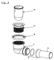
- the drain device 4 is off Fig. 3 detailed in an exploded view.
- the drain device 4 comprises a drain housing 7, which is designed as an angle-shaped piece of pipe.
- the drain housing 7 has an upper tube section 8 with an internal thread 9 and a neck 10 extending away from this tube section 8 at a right angle, which terminates in a part of the ball joint 6.
- the drain device further comprises a fastening part 11, which is substantially tubular and has an external thread 12. Furthermore, at the upper end of the fastening part 11, a radially outwardly extending flange 13 is arranged.
- the drain device further comprises an odor trap unit 14, which will be described in more detail below.
- an odor trap unit 14 At the upper end of the odor trap unit 14, a sealing ring 15 extending substantially radially outwards from the odor trap unit is mounted.
- the liquid passing through the drain opening 3 can enter from above. From the odor trap unit 14, the liquid can escape into the drain housing 7, in particular into the drain neck 10 of the drain housing 7.
- Fig. 2 is in detail the assembly of the drain device in the urinal inserted state visible.
- Fig. 2 can be removed that the fastening part 11 with its upper flange 13 on the area surrounding the drain opening 3 of the collecting basin. 2 rests.
- the drainage device 4 further comprises a second sealing ring 16 (see also Fig. 3 ) which rests on the upper side of a flange 17 extending radially outwards from the pipe section 8 and bears against the underside of the part of the collecting basin 2 which surrounds the discharge opening 3.
- the drain housing 7 By screwing the internal thread 9 with the external thread 12, the drain housing 7 is thus pressed from below against the sealing ring 16, whereas the flange 13 of the fastening part 11 is pressed from above against the area surrounding the drain opening 3 of the collecting basin 2. In this way, the drain device 4 is fixed to the sump 2.
- the odor trap unit 14 can be inserted from above through the drain opening 3 into the drain device 4. This is particularly because the odor closure unit 14 has a substantially cylindrical outer contour and the drain housing 7 with its upwardly open pipe section 8, the odor trap unit 14 can at least partially accommodate.
- the fastening part 11 has in its upper region on its inside a shoulder 18 on which the odor-sealing unit 14 connected to the first sealing ring 15 can rest.
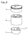
- the odor trap unit is off Fig. 4 in more detail.
- the odor closure unit 14 comprises three parts, a first, upper part 19, a second, middle part 20 and a third, lower part 21.
- the three parts 19, 20, 21 are made of plastic and can be produced in an injection molding process. After injection molding, the three parts 19, 20, 21 can be joined together by welding.
- the second, central part 20 is substantially tubular and has three, in the axial, or in the position of use in the vertical direction extending channels 23, 24, 25, which are parallel to each other.
- the first channel 23 is aligned in the vertical direction with the inlet opening 22, so that the liquid entering through the inlet opening 22 can enter the first channel 23 and leave it below.
- the liquid passed down through the channel 23 enters the third, lower part 21, which has an upwardly open liquid receiving space 26. From this receiving space 26, the liquid can rise through the second channel 24 upwards. From the upper end of the second channel 24, the liquid can enter the third channel 25 and flow down in this.
- the lower end of the third channel 25 opens into a recess 27, which extends from the outside into the third, lower part 21 of the odor trap unit 4.
- the liquid emerging from the third channel 25 thus does not enter the third part 21 but runs past it into the drain housing 7 and, in particular, through the drain neck 10 into the drain pipe 5.
- an intermediate wall may be provided which rests on the boundary of the first channel 23 of the second part 20 from above so that no liquid from the first channel 23 into the second channel on the top of the second part 20 24 or in the third channel 25 can occur. Nevertheless, however, the passage of liquid from the upper end of the second channel 24 into the upper end of the third channel 25 is ensured.
- the embodiment according to Fig. 3 and Fig. 4 differs from the embodiment according to Fig. 5 and Fig. 6 only insignificant.
- the embodiment according to Fig. 3 and Fig. 4 has a sensor means 28 which is arranged on the inside of the pipe section 8 of the drain housing 7. Accordingly, the odor sealing unit 14 and there in particular the second part 20 and the third part 21 each have a recess 29, 30, which serve to receive the sensor means 28.
- the sensor means 28 may detect, for example, a liquid flow or a temperature change and thus recognize the use of the urinal. After detection of the use of the urinal can be operated by a control unit, not shown, the flushing water for the catch basin 2.
- the illustrated embodiment does not include a sensor means.
Landscapes
- Engineering & Computer Science (AREA)
- Health & Medical Sciences (AREA)
- Life Sciences & Earth Sciences (AREA)
- Hydrology & Water Resources (AREA)
- Public Health (AREA)
- Water Supply & Treatment (AREA)
- Environmental & Geological Engineering (AREA)
- Sanitary Device For Flush Toilet (AREA)
- Sink And Installation For Waste Water (AREA)
Description
- Die vorliegende Erfindung betrifft ein Urinal gemäß dem Oberbegriff des Anspruchs 1.
- Ein Urinal der vorgenannten Art ist aus der internationalen Patentanmeldung
WO 2006/021819 A1 bekannt. Das darin beschriebene Urinal umfasst ein Auffangbecken mit einer Ablauföffnung für Urin und Wasser sowie eine Ablaufvorrichtung, die mit einem Ablaufrohr verbunden oder verbindbar ist und eine Geruchsverschlusseinheit aufweist. Die Geruchsverschlusseinheit ist von oben durch die Ablauföffnung in die Ablaufvorrichtung einbringbar. Weiterhin weist die Geruchsverschlusseinheit drei Teile auf, die in Gebrauchsstellung zumindest abschnittsweise übereinander angeordnet sind. Insbesondere umgreift das untere Teil den unteren Abschnitt des mittleren Teils, so dass dadurch ein Überlauf gebildet wird, der eine als Geruchsverschluss dienende Wassermenge vorhalten kann. - Ein weiteres Urinal ist aus der britischen Patentschrift
GB 1 269 910 - Ein weiteres Urinal ist aus der deutschen Patentschrift
41 20 768 C2 bekannt. Das darin beschriebene Urinal weist eine Ablaufvorrichtung auf, die einen Rohrstutzen umfasst, der an einem sich nach unten erstreckenden Ansatz des Auffangbeckens angebracht ist, wobei in diesen Ansatz die Ablauföffnung des Auffangbeckens mündet. - Unterhalb des Rohrstutzens ist eine als Siphon ausgebildete Geruchsverschlusseinheit vorgesehen, die mit einem Ablaufrohr verbunden ist. Das Urinal ist als Wandurinal ausgebildet und kann mit seiner Rückseite an einer Wand angebracht werden. Die Ablaufvorrichtung und insbesondere der Siphon sind derart in dem Urinal untergebracht, dass eine Reinigung oder ein Austausch des Siphons nur nach vorheriger Demontage des gesamten Urinals von der Wand möglich ist.
- Das der vorliegenden Erfindung zugrunde liegende Problem ist die Schaffung eines Urinals der eingangs genannten Art, bei dem die Geruchsverschlusseinheit einfach gesäubert und/oder einfach ausgetauscht werden kann.
- Dies wird erfindungsgemäß durch ein Urinal der eingangs genannten Art mit den kennzeichnenden Merkmalen des Anspruchs 1 erreicht. Die Unteransprüche betreffen bevorzugte Ausgestaltungen der Erfindung.
- Gemäß Anspruch 1 ist vorgesehen, dass die Geruchsverschlusseinheit abschnittsweise drei parallel zueinander verlaufende Kanäle aufweist, wobei durch den ersten der drei Kanäle in die Geruchsverschlusseinheit eingetretene Flüssigkeit nach unten geführt werden kann, wobei durch den zweiten der drei Kanäle die von dem ersten Kanal nach unten geführte Flüssigkeit wieder nach oben geführt werden kann, wobei von dem dritten der drei Kanäle die von dem zweiten Kanal nach oben geführte Flüssigkeit nach unten geführt werden kann, so dass sie aus der Geruchsverschlusseinheit heraus treten kann, und wobei die drei Kanäle in Umfangsrichtung der zylindrischen Außenkontur nebeneinander angeordnet sind, so dass jeder Kanal unmittelbar neben den anderen zwei Kanälen angeordnet ist.
- Durch eine zumindest abschnittsweise zylindrische Außenkontur, die sich im eingebauten Zustand im Wesentlichen vertikal erstreckt, kann die Geruchsverschlusseinheit vergleichsweise einfach durch die Ablauföffnung hindurchgeführt werden.
- Durch die Gestaltung mit drei zueinander parallelen Kanälen lässt sich mit einfachen Mitteln ein Geruchsverschluss mit einer vorgehaltenen Flüssigkeitsmenge realisieren.
- Die drei Teile können im Spritzgussverfahren hergestellt werden. Daran anschließend können die drei Teile miteinander verschweißt werden, so dass der Monteur vor Ort lediglich ein Teil einbauen muss, so dass sich insbesondere auch die Entnahme zur Reinigung oder zum Austausch erleichtert.
- Es besteht weiterhin die Möglichkeit, dass die Ablaufvorrichtung ein Ablaufgehäuse umfasst, in das die Geruchsverschlusseinheit zumindest teilweise von oben einbringbar ist. Dabei kann das Ablaufgehäuse mit dem Ablaufrohr verbindbar sein. Weiterhin kann das Ablaufgehäuse, insbesondere im Bereich der Ablauföffnung an dem Auffangbecken angebracht werden.
- Weiterhin besteht die Möglichkeit, dass die Ablaufvorrichtung ein Befestigungsteil umfasst, mittels dem das Ablaufgehäuse an dem Auffangbecken angebracht werden kann.
- Dabei kann vorgesehen sein, dass das Befestigungsteil ein Außengewinde aufweist und das Ablaufgehäuse ein Innengewinde aufweist, in das das Außengewinde des Befestigungsteils einschraubbar ist. Auf diese Weise kann durch Einschrauben des Innengewindes in das Außengewinde das Ablaufgehäuse vermittels des Befestigungsteils an dem Auffangbecken angebracht werden.
- Gemäß einer bevorzugten Ausgestaltung der vorliegenden Erfindung weist das Ablaufgehäuse einen oberen Flansch auf, der an der Unterseite des die Ablauföffnung umgebenen Bereich des Auffangbeckens anliegen kann. Beispielsweise kann in diesem Bereich auch eine Dichtung vorgesehen sein, die die Anlage des Ablaufgehäuses an der Unterseite des Auffangbeckens abdichtet.
- Weiterhin kann bevorzugt vorgesehen sein, dass das Befestigungsteil einen oberen Flansch aufweist, der auf der Oberseite des die Ablauföffnung umgebene Bereichs des Auffangbeckens oder beispielsweise einem darunter gebildeten Absatz des Auffangbeckens aufliegen kann. Da somit ein Teil des Befestigungsteils auf der Oberseite oder einem entsprechend darunter angeordneten Absatz aufliegen kann und das Ablaufgehäuse an der Unterseite des Auffangbeckens anliegen kann, wird durch Verschrauben des Befestigungsteils mit dem Ablaufgehäuse eine feste Anbringung des Ablaufgehäuses an dem Auffangbecken realisiert.
- Es kann insbesondere vorgesehen sein, dass das Befestigungsteil einen Absatz aufweist, auf dem ein Teil der Geruchsverschlusseinheit oder ein mit dieser verbundenes Teil, insbesondere eine mit dieser verbundene Dichtung, aufliegen kann. Die Geruchsverschlusseinheit kann somit von dem Befestigungsteil in der Ablaufvorrichtung, insbesondere in dem Ablaufgehäuse gehalten werden.
- Weitere Merkmale und Vorteile der vorliegenden Erfindung werden deutlich anhand der nachfolgenden Beschreibung bevorzugter Ausführungsbeispiele unter Bezugnahme auf die beiliegenden Abbildungen. Darin zeigen
- Fig. 1
- eine Schnittdarstellung eines erfindungsgemäßen Urinals;
- Fig. 2
- eine Detailvergrößerung gemäß dem Pfeil II in
Fig. 1 ; - Fig. 3
- eine Explosionsansicht einer ersten Ausführungsform einer Ablaufvorrichtung eines erfindungsgemäßen Urinals;
- Fig. 4
- eine Explosionsansicht einer Geruchsverschlusseinheit der Ablaufvorrichtung gemäß
Fig. 3 ; - Fig. 5
- eine Explosionsansicht einer zweiten Ausführungsform einer Ablaufvorrichtung eines erfindungsgemäßen Urinals;
- Fig. 6
- eine Explosionsansicht einer Geruchsverschlusseinheit der Ablaufvorrichtung gemäß
Fig. 5 . - Aus
Fig. 1 ist ersichtlich, dass ein erfindungsgemäßes Urinal einen beispielsweise aus Keramik bestehenden Urinalkörper 1 mit einem darin gebildeten Auffangbecken 2 für Urin und Wasser umfasst. Das Urinal umfasst weiterhin nicht abgebildete Mittel zur Wasserspülung des Auffangbeckens 2. Das Auffangbecken weist an seinem unteren Ende eine Ablauföffnung 3 auf, durch die der Urin und das Wasser das Auffangbecken 2 nach unten verlassen können. - Das Urinal umfasst weiterhin eine Ablaufvorrichtung 4, in die das durch die Ablauföffnung 3 geflossene Wasser hineintreten kann. Die Ablaufvorrichtung 4 ist mit einem Ablaufrohr 5 verbunden. In dem abgebildeten Ausführungsbeispiel geschieht diese Verbindung über ein Kugelgelenk 6, das eine einfachere Montage des Urinals ermöglicht.
- Die Ablaufvorrichtung 4 ist aus
Fig. 3 in einer Explosionsdarstellung detailliert ersichtlich. Die Ablaufvorrichtung 4 umfasst ein Ablaufgehäuse 7, das als winkelförmiges Rohrstück ausgebildet ist. Das Ablaufgehäuse 7 weist einen oberen Rohrabschnitt 8 mit einem Innengewinde 9 sowie einen sich von diesem Rohrstück 8 unter einem rechten Winkel wegerstreckenden Stutzen 10 auf, der in einem Teil des Kugelgelenks 6 endet. - Die Ablaufvorrichtung umfasst weiterhin ein Befestigungsteil 11, das im Wesentlichen rohrförmig ausgebildet ist und ein Außengewinde 12 aufweist. Weiterhin ist an dem oberen Ende des Befestigungsteils 11 ein sich radial nach außen erstreckender Flansch 13 angeordnet.
- Die Ablaufvorrichtung umfasst weiterhin eine Geruchsverschlusseinheit 14, die im Nachfolgenden noch detaillierter beschrieben wird. An dem oberen Ende der Geruchsverschlusseinheit 14 ist ein sich von der Geruchsverschlusseinheit im Wesentlichen radial nach außen erstreckender Dichtring 15 angebracht. In die Geruchsverschlusseinheit 14 kann von oben die durch die Ablauföffnung 3 hindurch tretende Flüssigkeit eintreten. Aus der Geruchsverschlusseinheit 14 kann die Flüssigkeit in das Ablaufgehäuse 7, insbesondere in den Ablaufstutzen 10 des Ablaufgehäuses 7 austreten.
- Aus
Fig. 2 ist detailliert der Zusammenbau der Ablaufvorrichtung im in das Urinal eingesetzten Zustand ersichtlich.Fig. 2 ist entnehmbar, dass das Befestigungsteil 11 mit seinem oberen Flansch 13 auf dem die Ablauföffnung 3 umgebenden Bereich des Auffangbeckens 2 aufliegt. Weiterhin ist ersichtlich, dass die Ablaufvorrichtung 4 weiterhin einen zweiten Dichtring 16 umfasst (siehe dazu auchFig. 3 ) der auf der Oberseite eines sich von dem Rohrstück 8 radial nach außen erstreckenden Flansches 17 aufliegt und an der Unterseite des die Ablauföffnung 3 umgebenen Teils des Auffangbeckens 2 anliegt. Durch ineinander Verschrauben des Innengewindes 9 mit dem Außengewinde 12 wird somit das Ablaufgehäuse 7 von unten gegen den Dichtring 16 gepresst, wohingegen der Flansch 13 des Befestigungsteils 11 von oben gegen den die Ablauföffnung 3 umgebenden Bereich des Auffangbeckens 2 gedrückt wird. Auf diese Weise wird die Ablaufvorrichtung 4 an dem Auffangbecken 2 festgelegt. - Die Geruchsverschlusseinheit 14 kann von oben durch die Ablauföffnung 3 in die Ablaufvorrichtung 4 eingeschoben werden. Dies insbesondere deshalb, weil die Geruchsverschlusseinheit 14 eine im Wesentlichen zylindrische Außenkontur aufweist und das Ablaufgehäuse 7 mit seinem nach oben offenen Rohrstück 8 die Geruchsverschlusseinheit 14 zumindest teilweise aufnehmen kann. Dabei weist das Befestigungsteil 11 in seinem oberen Bereich auf seiner Innenseite einen Absatz 18 auf, auf dem der mit der Geruchsverschlusseinheit 14 verbundene erste Dichtring 15 aufliegen kann.
- Die Geruchsverschlusseinheit ist aus
Fig. 4 detaillierter ersichtlich. Die Geruchsverschlusseinheit 14 umfasst drei Teile, ein erstes, oberes Teil 19, ein zweites, mittleres Teil 20 und ein drittes, unteres Teil 21. Die drei Teile 19, 20, 21 bestehen aus Kunststoff und können in einem Spritzgussverfahren hergestellt werden. Nach dem Spritzgießen können die drei Teile 19, 20, 21 durch Schweißen miteinander verbunden werden. - In dem ersten, oberen Teil 19 ist eine Einlauföffnung 22 für die durch die Ablauföffnung 3 hindurchgetretene Flüssigkeit vorgesehen. Das zweite, mittlere Teil 20 ist im Wesentlichen rohrförmig ausgebildet und weist drei, sich in axialer, beziehungsweise sich in Gebrauchsstellung in vertikaler Richtung erstreckende Kanäle 23, 24, 25 auf, die parallel zueinander verlaufen. Der erste Kanal 23 fluchtet in vertikaler Richtung mit der Einlauföffnung 22, so dass die durch die Einlauföffnung 22 eingetretene Flüssigkeit in den ersten Kanal 23 eintreten kann und diesen unten verlassen kann. Die durch den Kanal 23 nach unten hindurchgetretene Flüssigkeit tritt in das dritte, untere Teil 21 ein, das einen nach oben offenen Aufnahmeraum 26 für Flüssigkeit aufweist. Von diesem Aufnahmeraum 26 kann die Flüssigkeit durch den zweiten Kanal 24 nach oben steigen. Von dem oberen Ende des zweiten Kanals 24 kann die Flüssigkeit in den dritten Kanal 25 gelangen und in diesem nach unten fließen.
- Das untere Ende des dritten Kanals 25 mündet in eine Einbuchtung 27, die sich von außen in das dritte, untere Teil 21 der Geruchsverschlusseinheit 4 hineinerstreckt. Die aus dem dritten Kanal 25 nach unten austretende Flüssigkeit gelangt somit nicht in das dritte Teil 21 sondern läuft an diesem vorbei in das Ablaufgehäuse 7 und dort insbesondere durch den Ablaufstutzen 10 in das Ablaufrohr 5.
- In dem ersten Teil 19 der Geruchsverschlusseinheit 4 kann eine Zwischenwand vorgesehen sein, die auf der Begrenzung des ersten Kanals 23 des zweiten Teils 20 derart von oben aufsitzt, dass auf der Oberseite des zweiten Teils 20 keine Flüssigkeit aus dem ersten Kanal 23 in den zweiten Kanal 24 oder in den dritten Kanal 25 eintreten kann. Trotzdem wird aber der Übertritt von Flüssigkeit aus dem oberen Ende des zweiten Kanals 24 in das obere Ende des dritten Kanals 25 gewährleistet.
- Die Ausführungsform gemäß
Fig. 3 undFig. 4 unterscheidet sich von der Ausführungsform gemäßFig. 5 undFig. 6 nur unwesentlich. Insbesondere sind hier gleiche Teile mit gleichen Bezugszeichen versehen. Die Ausführungsform gemäßFig. 3 undFig. 4 weist ein Sensormittel 28 auf, das an der Innenseite des Rohrstückes 8 des Ablaufgehäuses 7 angeordnet ist. Dementsprechend weist auch die Geruchsverschlusseinheit 14 und dort insbesondere das zweite Teil 20 und das dritte Teil 21 jeweils eine Ausnehmung 29, 30 auf, die zur Aufnahme des Sensormittels 28 dienen. Das Sensormittel 28 kann beispielsweise eine Flüssigkeitsströmung oder eine Temperaturänderung detektieren und auf diese Weise die Benutzung des Urinals erkennen. Nach Erkennung der Benutzung des Urinals kann von einer nicht abgebildeten Steuereinheit die Wasserspülung für das Auffangbecken 2 betätigt werden. - Die in
Fig. 5 undFig. 6 abgebildete Ausführungsform umfasst kein Sensormittel. -
- 1
- Urinalkörper
- 2
- Auffangbecken
- 3
- Ablauföffnung
- 4
- Ablaufvorrichtung
- 5
- Ablaufrohr
- 6
- Kugelgelenk
- 7
- Ablaufgehäuse
- 8
- Rohrstück
- 9
- Innengewinde
- 10
- Stutzen
- 11
- Befestigungsteil
- 12
- Außengewinde
- 13
- Flansch
- 14
- Geruchsverschlusseinheit
- 15
- Erster Dichtring
- 16
- Zweiter Dichtring
- 17
- Flansch an 8
- 18
- Absatz
- 19
- Erstes, oberes Teil
- 20
- Zweites, mittleres Teil
- 21
- Drittes, unteres Teil
- 22
- Einlauföffnung
- 23
- Erster Kanal
- 24
- Zweiter Kanal
- 25
- Dritter Kanal
- 26
- Aufnahmeraum für Flüssigkeit in 21
- 27
- Einbuchtung in 21
- 28
- Sensormittel
- 29
- Ausnehmung für 28
- 30
- Ausnehmung für 28
Claims (14)
- Urinal, insbesondere an einer Wand anbringbares Urinal, umfassend- ein Auffangbecken (2) mit einer Ablauföffnung (3) für Urin und Wasser;- Mittel zur Wasserspülung des Auffangbeckens (2);- eine Ablaufvorrichtung (4), die mit einem Ablaufrohr (5) verbunden oder verbindbar ist und eine Geruchsverschlusseinheit (14) aufweist, wobei in die Ablauflaufvorrichtung (4) durch die Ablauföffnung (3) Flüssigkeit eintreten, durch die Geruchsverschiusseinheit (14) hindurchtreten und in das Ablaufrohr (5) wieder austreten kann, wobei das Urinal und/oder die Ablaufvorrichtung (4) und/oder die Geruchsverschlusseinheit (14) derart ausgebildet sind, dass die Geruchsverschlusseinheit (14) von oben durch die Ablauföffnung (3) zumindest teilweise in die Ablaufvorrichtung (4) einbringbar ist, und wobei die Geruchsverschlusseinheit (14) zumindest abschnittsweise eine zylindrische Außenkontur aufweist, wobei sich die Zylinderachse dieser Außenkontur im eingebauten Zustand im Wesentlichen vertikal erstreckt;dadurch gekennzeichnet, dass die Geruchsverschlusseinheit (14) abschnittsweise drei parallel zueinander verlaufende Kanäle (23, 24, 25) aufweist, wobei durch den ersten der drei Kanäle (23, 24, 25) in die Geruchsverschlusseinheit (14) eingetretene Flüssigkeit nach unten geführt werden kann, wobei durch den zweiten der drei Kanäle (23, 24, 25) die von dem ersten Kanal (23) nach unten geführte Flüssigkeit wieder nach oben geführt werden kann, wobei von dem dritten der drei Kanäle (23, 24, 25) die von dem zweiten Kanal (24) nach oben geführte Flüssigkeit nach unten geführt werden kann, so dass sie aus der Geruchsverschlusseinheit (14) heraus treten kann, und wobei die drei Kanäle (23, 24, 25) in Umfangsrichtung der zylindrischen Außenkontur nebeneinander angeordnet sind so dass jeder Kanal (23, 24, 25) unmittelbar neben den anderen zwei Kanälen (23, 24, 25) angeordnet ist.
- Urinal nach Anspruch 1, dadurch gekennzeichnet, dass die Geruchsverschlusseinheit (14) derart ausgebildet ist, dass in ihr eine Flüssigkeitsmenge für den Geruchsverschluss vorgehalten werden kann.
- Urinal nach einem der Ansprüche 1 oder 2, dadurch gekennzeichnet, dass die Geruchsverschlusseinheit (14) drei Teile (19, 20, 21) umfasst, die in Gebrauchsstellung übereinander angeordnet sind, wobei insbesondere die drei Kanäle (23, 24, 25) in dem mittleren Teil (20) angeordnet sind.
- Urinal nach einem der Ansprüche 1 bis 3, dadurch gekennzeichnet, dass die Ablaufvorrichtung (4) ein Ablaufgehäuse (7) umfasst, in das die Geruchsverschlusseinheit (14) zumindest teilweise von oben einbringbar ist.
- Urinal nach Anspruch 4, dadurch gekennzeichnet, dass das Ablaufgehäuse (7) mit dem Ablaufrohr (5) verbindbar ist.
- Urinal nach einem der Ansprüche 4 oder 5, dadurch gekennzeichnet, dass das Ablaufgehäuse (7), insbesondere im Bereich der Ablauföffnung (3), an dem Auffangbecken (2) angebracht werden kann.
- Urinal nach Anspruch 6, dadurch gekennzeichnet, dass die Ablaufvorrichtung (4) ein Befestigungsteil (11) umfasst, mittels dem das Ablaufgehäuse (7) an dem Auffangbecken (2) angebracht werden kann.
- Urinal nach Anspruch 7, dadurch gekennzeichnet, dass das Befestigungsteil (11) ein Außengewinde (12) aufweist und das Ablaufgehäuse (7) ein Innengewinde (9) aufweist, in das das Außengewinde (12) des Befestigungsteils (11) einschraubbar ist.
- Urinal nach einem der Ansprüche 4 bis 8, dadurch gekennzeichnet, dass das Ablaufgehäuse (7) einen oberen Flansch (17) aufweist, der an der Unterseite des die Ablauföffnung (3) umgebenden Bereichs des Auffangbeckens (2) anliegen kann.
- Urinal nach einem der Ansprüche 7 bis 9, dadurch gekennzeichnet, dass das Befestigungsteil (11) einen oberen Flansch (13) aufweist, der auf der Oberseite des die Ablauföffnung (3) umgebenden Bereichs des Auffangbeckens (2) oder einem darunter gebildeten Absatz des Auffangbeckens (2) aufliegen kann.
- Urinal nach einem der Ansprüche 7 bis 10, dadurch gekennzeichnet, dass das Befestigungsteil (11) einen Ansatz (18) aufweist, auf dem ein Teil der Geruchsverschlusseinheit (14) oder ein mit dieser verbundenes Teil, insbesondere eine mit dieser verbundene Dichtung oder ein mit dieser verbundener Dichtring (15), aufliegen kann.
- Urinal nach einem der Ansprüche 1 bis 11, dadurch gekennzeichnet, dass das Urinal ein Sensormittel (28) umfasst, das beispielsweise auf eine Flüssigkeitsströmung und/oder eine Temperaturänderung reagieren kann.
- Urinal nach Anspruch 12, dadurch gekennzeichnet, dass das Sensormittel (28) an der Innenseite des Ablaufgehäuses (7) angeordnet ist.
- Urinal nach einem der Ansprüche 12 oder 13, dadurch gekennzeichnet, dass die Geruchsverschlusseinheit (14) eine äußere Ausnehmung (29, 30) für den Eingriff des Sensormittels 28) aufweist.
Priority Applications (3)
| Application Number | Priority Date | Filing Date | Title |
|---|---|---|---|
| EP06006199A EP1837447B1 (de) | 2006-03-25 | 2006-03-25 | Urinal |
| AT06006199T ATE509163T1 (de) | 2006-03-25 | 2006-03-25 | Urinal |
| ES06006199T ES2366127T3 (es) | 2006-03-25 | 2006-03-25 | Urinario. |
Applications Claiming Priority (1)
| Application Number | Priority Date | Filing Date | Title |
|---|---|---|---|
| EP06006199A EP1837447B1 (de) | 2006-03-25 | 2006-03-25 | Urinal |
Publications (2)
| Publication Number | Publication Date |
|---|---|
| EP1837447A1 EP1837447A1 (de) | 2007-09-26 |
| EP1837447B1 true EP1837447B1 (de) | 2011-05-11 |
Family
ID=36781962
Family Applications (1)
| Application Number | Title | Priority Date | Filing Date |
|---|---|---|---|
| EP06006199A Expired - Lifetime EP1837447B1 (de) | 2006-03-25 | 2006-03-25 | Urinal |
Country Status (3)
| Country | Link |
|---|---|
| EP (1) | EP1837447B1 (de) |
| AT (1) | ATE509163T1 (de) |
| ES (1) | ES2366127T3 (de) |
Cited By (2)
| Publication number | Priority date | Publication date | Assignee | Title |
|---|---|---|---|---|
| EP2664721A2 (de) | 2012-05-18 | 2013-11-20 | VIEGA GmbH & Co. KG | Ablaufarmatur für ein Ablaufbecken, insbesondere Urinal, mit einem Absaugsiphon |
| WO2017036319A1 (zh) * | 2015-08-31 | 2017-03-09 | 徐旭东 | 一种立式节水小便池 |
Families Citing this family (1)
| Publication number | Priority date | Publication date | Assignee | Title |
|---|---|---|---|---|
| JP6607341B2 (ja) | 2015-01-20 | 2019-11-20 | Toto株式会社 | 小便器 |
Family Cites Families (5)
| Publication number | Priority date | Publication date | Assignee | Title |
|---|---|---|---|---|
| SE341671B (de) | 1969-12-23 | 1972-01-10 | C Sjoeberg | |
| DE4000104A1 (de) * | 1990-01-04 | 1991-07-11 | Dallmer Gmbh & Co | Ablaufarmatur fuer eine brausewanne |
| DE4120768C2 (de) | 1991-06-24 | 2001-02-15 | Duravit Ag | Wandurinal |
| CA2118999C (en) * | 1993-04-04 | 1997-12-16 | Klaus H. Reichardt | Waterless urinal |
| GB0418971D0 (en) | 2004-08-25 | 2004-09-29 | Enviro Fresh Ltd | Waste outlet assembly |
-
2006
- 2006-03-25 AT AT06006199T patent/ATE509163T1/de active
- 2006-03-25 EP EP06006199A patent/EP1837447B1/de not_active Expired - Lifetime
- 2006-03-25 ES ES06006199T patent/ES2366127T3/es not_active Expired - Lifetime
Cited By (2)
| Publication number | Priority date | Publication date | Assignee | Title |
|---|---|---|---|---|
| EP2664721A2 (de) | 2012-05-18 | 2013-11-20 | VIEGA GmbH & Co. KG | Ablaufarmatur für ein Ablaufbecken, insbesondere Urinal, mit einem Absaugsiphon |
| WO2017036319A1 (zh) * | 2015-08-31 | 2017-03-09 | 徐旭东 | 一种立式节水小便池 |
Also Published As
| Publication number | Publication date |
|---|---|
| ES2366127T3 (es) | 2011-10-17 |
| ATE509163T1 (de) | 2011-05-15 |
| EP1837447A1 (de) | 2007-09-26 |
Similar Documents
| Publication | Publication Date | Title |
|---|---|---|
| EP1905907B1 (de) | Ablaufvorrichtung für die zumindest teilweise Einbringung in einen Boden eines Raumes | |
| EP2108750B1 (de) | Ablaufarmatur für Bade- oder Duschwannen mit Bodenzulauf | |
| EP2045403A1 (de) | Ablaufgarnitur mit integriertem Überlauf | |
| EP1229174B1 (de) | Ablauf | |
| EP2230359A2 (de) | Bausatz für eine Verbindung eines Inspektions-Schachtes mit einer Abfluss-Leitung | |
| DE202012103132U1 (de) | Ablaufanordnung für Wasserarmaturen | |
| DE202010015319U1 (de) | Ablaufgarnitur mit verdeckt positionierbarem Überlauf | |
| EP1335076B1 (de) | Ablaufarmatur für eine Sanitärvorrichtung, insbesondere Urinal | |
| DE202005002415U1 (de) | Bauteilsatz zum modularen Erstellen einer Ablaufanordnung | |
| EP2157247B1 (de) | Ablauf | |
| EP1447485B1 (de) | Ablaufeinrichtung | |
| DE19741827B4 (de) | Ablaufarmatur für Bade- oder Duschwannen | |
| DE202008011010U1 (de) | Ablauf | |
| EP1837447B1 (de) | Urinal | |
| EP2258905B1 (de) | Ablauf, insbesondere für sanitäre Einrichtungen | |
| WO2017118583A1 (de) | Ventilarmatur für die befüllung eines sanitären spülkastens und sanitärer spülkasten mit einer solchen ventilarmatur | |
| DE102005036576B4 (de) | Ablaufvorrichtung für die Anordnung an einer Bodenplatte mit einer Öffung für Abwasser | |
| DE10201347B4 (de) | Einlaufvorrichtung für die Abführung von Regenwasser von einem Dach | |
| EP3502364A2 (de) | Rohrbelüfter und system zur rohrbelüftung | |
| EP1775395B1 (de) | Ablaufarmatur für sanitäre Anlagen | |
| EP3988724A1 (de) | Einlaufvorrichtung, wannenkörper und verfahren | |
| DE10360310A1 (de) | Ablaufvorrichtung | |
| DE202015107000U1 (de) | Ablaufsystem | |
| WO1999015736A1 (de) | Urinanlage aus keramik, glas oder metall | |
| EP4417893A1 (de) | Kondensatablaufvorrichtung für ein heizgerät und heizgerät |
Legal Events
| Date | Code | Title | Description |
|---|---|---|---|
| PUAI | Public reference made under article 153(3) epc to a published international application that has entered the european phase |
Free format text: ORIGINAL CODE: 0009012 |
|
| AK | Designated contracting states |
Kind code of ref document: A1 Designated state(s): AT BE BG CH CY CZ DE DK EE ES FI FR GB GR HU IE IS IT LI LT LU LV MC NL PL PT RO SE SI SK TR |
|
| AX | Request for extension of the european patent |
Extension state: AL BA HR MK YU |
|
| 17P | Request for examination filed |
Effective date: 20080326 |
|
| AKX | Designation fees paid |
Designated state(s): AT BE BG CH CY CZ DE DK EE ES FI FR GB GR HU IE IS IT LI LT LU LV MC NL PL PT RO SE SI SK TR |
|
| 17Q | First examination report despatched |
Effective date: 20080530 |
|
| GRAP | Despatch of communication of intention to grant a patent |
Free format text: ORIGINAL CODE: EPIDOSNIGR1 |
|
| GRAS | Grant fee paid |
Free format text: ORIGINAL CODE: EPIDOSNIGR3 |
|
| GRAA | (expected) grant |
Free format text: ORIGINAL CODE: 0009210 |
|
| AK | Designated contracting states |
Kind code of ref document: B1 Designated state(s): AT BE BG CH CY CZ DE DK EE ES FI FR GB GR HU IE IS IT LI LT LU LV MC NL PL PT RO SE SI SK TR |
|
| REG | Reference to a national code |
Ref country code: GB Ref legal event code: FG4D Free format text: NOT ENGLISH |
|
| REG | Reference to a national code |
Ref country code: CH Ref legal event code: EP |
|
| REG | Reference to a national code |
Ref country code: IE Ref legal event code: FG4D |
|
| REG | Reference to a national code |
Ref country code: DE Ref legal event code: R096 Ref document number: 502006009470 Country of ref document: DE Effective date: 20110622 |
|
| REG | Reference to a national code |
Ref country code: NL Ref legal event code: T3 |
|
| REG | Reference to a national code |
Ref country code: ES Ref legal event code: FG2A Ref document number: 2366127 Country of ref document: ES Kind code of ref document: T3 Effective date: 20111017 |
|
| PG25 | Lapsed in a contracting state [announced via postgrant information from national office to epo] |
Ref country code: LT Free format text: LAPSE BECAUSE OF FAILURE TO SUBMIT A TRANSLATION OF THE DESCRIPTION OR TO PAY THE FEE WITHIN THE PRESCRIBED TIME-LIMIT Effective date: 20110511 Ref country code: SE Free format text: LAPSE BECAUSE OF FAILURE TO SUBMIT A TRANSLATION OF THE DESCRIPTION OR TO PAY THE FEE WITHIN THE PRESCRIBED TIME-LIMIT Effective date: 20110511 Ref country code: PT Free format text: LAPSE BECAUSE OF FAILURE TO SUBMIT A TRANSLATION OF THE DESCRIPTION OR TO PAY THE FEE WITHIN THE PRESCRIBED TIME-LIMIT Effective date: 20110912 |
|
| PG25 | Lapsed in a contracting state [announced via postgrant information from national office to epo] |
Ref country code: IS Free format text: LAPSE BECAUSE OF FAILURE TO SUBMIT A TRANSLATION OF THE DESCRIPTION OR TO PAY THE FEE WITHIN THE PRESCRIBED TIME-LIMIT Effective date: 20110911 Ref country code: GR Free format text: LAPSE BECAUSE OF FAILURE TO SUBMIT A TRANSLATION OF THE DESCRIPTION OR TO PAY THE FEE WITHIN THE PRESCRIBED TIME-LIMIT Effective date: 20110812 Ref country code: LV Free format text: LAPSE BECAUSE OF FAILURE TO SUBMIT A TRANSLATION OF THE DESCRIPTION OR TO PAY THE FEE WITHIN THE PRESCRIBED TIME-LIMIT Effective date: 20110511 Ref country code: CY Free format text: LAPSE BECAUSE OF FAILURE TO SUBMIT A TRANSLATION OF THE DESCRIPTION OR TO PAY THE FEE WITHIN THE PRESCRIBED TIME-LIMIT Effective date: 20110511 Ref country code: FI Free format text: LAPSE BECAUSE OF FAILURE TO SUBMIT A TRANSLATION OF THE DESCRIPTION OR TO PAY THE FEE WITHIN THE PRESCRIBED TIME-LIMIT Effective date: 20110511 Ref country code: SI Free format text: LAPSE BECAUSE OF FAILURE TO SUBMIT A TRANSLATION OF THE DESCRIPTION OR TO PAY THE FEE WITHIN THE PRESCRIBED TIME-LIMIT Effective date: 20110511 |
|
| REG | Reference to a national code |
Ref country code: IE Ref legal event code: FD4D |
|
| PG25 | Lapsed in a contracting state [announced via postgrant information from national office to epo] |
Ref country code: CZ Free format text: LAPSE BECAUSE OF FAILURE TO SUBMIT A TRANSLATION OF THE DESCRIPTION OR TO PAY THE FEE WITHIN THE PRESCRIBED TIME-LIMIT Effective date: 20110511 Ref country code: EE Free format text: LAPSE BECAUSE OF FAILURE TO SUBMIT A TRANSLATION OF THE DESCRIPTION OR TO PAY THE FEE WITHIN THE PRESCRIBED TIME-LIMIT Effective date: 20110511 Ref country code: IE Free format text: LAPSE BECAUSE OF FAILURE TO SUBMIT A TRANSLATION OF THE DESCRIPTION OR TO PAY THE FEE WITHIN THE PRESCRIBED TIME-LIMIT Effective date: 20110511 |
|
| PG25 | Lapsed in a contracting state [announced via postgrant information from national office to epo] |
Ref country code: PL Free format text: LAPSE BECAUSE OF FAILURE TO SUBMIT A TRANSLATION OF THE DESCRIPTION OR TO PAY THE FEE WITHIN THE PRESCRIBED TIME-LIMIT Effective date: 20110511 Ref country code: DK Free format text: LAPSE BECAUSE OF FAILURE TO SUBMIT A TRANSLATION OF THE DESCRIPTION OR TO PAY THE FEE WITHIN THE PRESCRIBED TIME-LIMIT Effective date: 20110511 Ref country code: RO Free format text: LAPSE BECAUSE OF FAILURE TO SUBMIT A TRANSLATION OF THE DESCRIPTION OR TO PAY THE FEE WITHIN THE PRESCRIBED TIME-LIMIT Effective date: 20110511 Ref country code: SK Free format text: LAPSE BECAUSE OF FAILURE TO SUBMIT A TRANSLATION OF THE DESCRIPTION OR TO PAY THE FEE WITHIN THE PRESCRIBED TIME-LIMIT Effective date: 20110511 |
|
| PLBE | No opposition filed within time limit |
Free format text: ORIGINAL CODE: 0009261 |
|
| STAA | Information on the status of an ep patent application or granted ep patent |
Free format text: STATUS: NO OPPOSITION FILED WITHIN TIME LIMIT |
|
| 26N | No opposition filed |
Effective date: 20120214 |
|
| PG25 | Lapsed in a contracting state [announced via postgrant information from national office to epo] |
Ref country code: IT Free format text: LAPSE BECAUSE OF FAILURE TO SUBMIT A TRANSLATION OF THE DESCRIPTION OR TO PAY THE FEE WITHIN THE PRESCRIBED TIME-LIMIT Effective date: 20110511 |
|
| REG | Reference to a national code |
Ref country code: DE Ref legal event code: R097 Ref document number: 502006009470 Country of ref document: DE Effective date: 20120214 |
|
| BERE | Be: lapsed |
Owner name: DALLMER G.M.B.H. & CO. KG Effective date: 20120331 |
|
| PG25 | Lapsed in a contracting state [announced via postgrant information from national office to epo] |
Ref country code: MC Free format text: LAPSE BECAUSE OF NON-PAYMENT OF DUE FEES Effective date: 20120331 |
|
| PG25 | Lapsed in a contracting state [announced via postgrant information from national office to epo] |
Ref country code: BE Free format text: LAPSE BECAUSE OF NON-PAYMENT OF DUE FEES Effective date: 20120331 |
|
| PG25 | Lapsed in a contracting state [announced via postgrant information from national office to epo] |
Ref country code: BG Free format text: LAPSE BECAUSE OF FAILURE TO SUBMIT A TRANSLATION OF THE DESCRIPTION OR TO PAY THE FEE WITHIN THE PRESCRIBED TIME-LIMIT Effective date: 20110811 |
|
| PG25 | Lapsed in a contracting state [announced via postgrant information from national office to epo] |
Ref country code: LU Free format text: LAPSE BECAUSE OF NON-PAYMENT OF DUE FEES Effective date: 20120325 |
|
| PG25 | Lapsed in a contracting state [announced via postgrant information from national office to epo] |
Ref country code: HU Free format text: LAPSE BECAUSE OF FAILURE TO SUBMIT A TRANSLATION OF THE DESCRIPTION OR TO PAY THE FEE WITHIN THE PRESCRIBED TIME-LIMIT Effective date: 20060325 |
|
| REG | Reference to a national code |
Ref country code: FR Ref legal event code: PLFP Year of fee payment: 10 |
|
| PGFP | Annual fee paid to national office [announced via postgrant information from national office to epo] |
Ref country code: ES Payment date: 20150317 Year of fee payment: 10 Ref country code: NL Payment date: 20150319 Year of fee payment: 10 Ref country code: CH Payment date: 20150319 Year of fee payment: 10 |
|
| PGFP | Annual fee paid to national office [announced via postgrant information from national office to epo] |
Ref country code: AT Payment date: 20150320 Year of fee payment: 10 Ref country code: GB Payment date: 20150319 Year of fee payment: 10 Ref country code: FR Payment date: 20150319 Year of fee payment: 10 |
|
| REG | Reference to a national code |
Ref country code: CH Ref legal event code: PL |
|
| REG | Reference to a national code |
Ref country code: AT Ref legal event code: MM01 Ref document number: 509163 Country of ref document: AT Kind code of ref document: T Effective date: 20160325 |
|
| REG | Reference to a national code |
Ref country code: NL Ref legal event code: MM Effective date: 20160401 |
|
| GBPC | Gb: european patent ceased through non-payment of renewal fee |
Effective date: 20160325 |
|
| REG | Reference to a national code |
Ref country code: FR Ref legal event code: ST Effective date: 20161130 |
|
| PG25 | Lapsed in a contracting state [announced via postgrant information from national office to epo] |
Ref country code: LI Free format text: LAPSE BECAUSE OF NON-PAYMENT OF DUE FEES Effective date: 20160331 Ref country code: NL Free format text: LAPSE BECAUSE OF NON-PAYMENT OF DUE FEES Effective date: 20160401 Ref country code: GB Free format text: LAPSE BECAUSE OF NON-PAYMENT OF DUE FEES Effective date: 20160325 Ref country code: CH Free format text: LAPSE BECAUSE OF NON-PAYMENT OF DUE FEES Effective date: 20160331 Ref country code: FR Free format text: LAPSE BECAUSE OF NON-PAYMENT OF DUE FEES Effective date: 20160331 |
|
| PG25 | Lapsed in a contracting state [announced via postgrant information from national office to epo] |
Ref country code: AT Free format text: LAPSE BECAUSE OF NON-PAYMENT OF DUE FEES Effective date: 20160325 |
|
| PGFP | Annual fee paid to national office [announced via postgrant information from national office to epo] |
Ref country code: TR Payment date: 20150325 Year of fee payment: 10 |
|
| PG25 | Lapsed in a contracting state [announced via postgrant information from national office to epo] |
Ref country code: ES Free format text: LAPSE BECAUSE OF NON-PAYMENT OF DUE FEES Effective date: 20160326 |
|
| REG | Reference to a national code |
Ref country code: ES Ref legal event code: FD2A Effective date: 20181207 |
|
| PG25 | Lapsed in a contracting state [announced via postgrant information from national office to epo] |
Ref country code: TR Free format text: LAPSE BECAUSE OF NON-PAYMENT OF DUE FEES Effective date: 20160325 |
|
| P01 | Opt-out of the competence of the unified patent court (upc) registered |
Effective date: 20230616 |
|
| PGFP | Annual fee paid to national office [announced via postgrant information from national office to epo] |
Ref country code: DE Payment date: 20250331 Year of fee payment: 20 |
|
| REG | Reference to a national code |
Ref country code: DE Ref legal event code: R071 Ref document number: 502006009470 Country of ref document: DE |