EP1840680B1 - Module horloger comportant un cadran rotatif ajustable sur un mouvement horloger - Google Patents
Module horloger comportant un cadran rotatif ajustable sur un mouvement horloger Download PDFInfo
- Publication number
- EP1840680B1 EP1840680B1 EP06006515A EP06006515A EP1840680B1 EP 1840680 B1 EP1840680 B1 EP 1840680B1 EP 06006515 A EP06006515 A EP 06006515A EP 06006515 A EP06006515 A EP 06006515A EP 1840680 B1 EP1840680 B1 EP 1840680B1
- Authority
- EP
- European Patent Office
- Prior art keywords
- stop
- rotary dial
- pusher
- rod
- pins
- Prior art date
- Legal status (The legal status is an assumption and is not a legal conclusion. Google has not performed a legal analysis and makes no representation as to the accuracy of the status listed.)
- Expired - Lifetime
Links
Images


Classifications
-
- G—PHYSICS
- G04—HOROLOGY
- G04B—MECHANICALLY-DRIVEN CLOCKS OR WATCHES; MECHANICAL PARTS OF CLOCKS OR WATCHES IN GENERAL; TIME PIECES USING THE POSITION OF THE SUN, MOON OR STARS
- G04B45/00—Time pieces of which the indicating means or cases provoke special effects, e.g. aesthetic effects
- G04B45/02—Time pieces of which the clockwork is visible partly or wholly
Definitions
- the present invention relates to the field of watchmaking, more particularly to a watch module comprising a rotary dial adjustable on a watch movement.
- the dial has an opening for viewing one of the complications of the watch movement, the action of a pusher pivoting said dial to view another complication or image.
- the publication US 2003/0095475 discloses a watch whose dial includes a planisphere map of the constellations.
- the bezel is provided with a crescent-shaped cover on which the hour digits are written, these figures being able to align with the days of the year, the latter being arranged on the periphery of a concentric ring.
- the rotation of the telescope coincides with the date to reveal the portion of the map that can be observed in the sky at a specific time during the year.
- the rotation of the telescope is done manually.
- the aim of the present invention is to propose a watch module comprising an adjustable rotary dial on a watch movement, said rotary dial having an opening making it possible to display only one piece of information at a time in order to facilitate the reading of the watch. information and on the other hand to ensure a certain sobriety of the watch.
- this object is achieved by means of a watch module according to claim 1.
- the detuning of the rotary dial of the base dial is performed when pressure is exerted on the pusher, the rotation the rotary dial being triggered when the pusher returns to its rest position.
- the watch module comprises the rotary dial (1) comprising the opening (2).
- Said dial (1) is rotatably arranged on the base dial (3) via a ball bearing (4).
- the base dial (3) has four openings (5) each positioned at 90 degrees to reveal four complications of the watch movement.
- the rotary dial (1) has on the lower face on the one hand an annular element (6) at its center on which are positioned at regular intervals the four drive pins (7) and on the other hand the other four pins of stops (8) positioned at its periphery also at regular intervals, this in correspondence with the drive pins (7).
- Each of the four drive pins (7) is intended to be driven by an instantaneous mechanism, which will be described later, to ensure the rotation of the rotary dial (1) by 90 degrees when a pusher (9, 9 ') is operated.
- Each of the stop pins (8) is intended to stop the rotation of the rotary dial (1) when it has rotated 90 degrees.
- the watch module has two identical control systems positioned symmetrically with respect to the 3H / 9H axis, one of which rotates the rotary dial (1) clockwise and the other causes it to rotate. counterclockwise, only the action of one of these systems will be described.
- the pusher (9) engages the instantaneous rotation of the rotary dial (1) through the various sequences mentioned above, however, when one of the stop pins (8) is stopped by the stop finger (13), the rotary dial (1), having rotated 90 degrees, is found in an unstable position, To overcome this problem, the rotary dial (1) has on its periphery four bosses (19) associated with the pins stops (8). These are intended to be positioned in turn in a housing (20) located on a spring blade (21) thereby ensuring the stability of the rotary dial (1).
- This leaf spring (21) is arranged in a recess (not shown) in the base dial (3).
- the latter has an opening (22) ( Figure 1 ) at 10H to position the finger (13) of the so-called stop rocker (12) at the stop pins (8).
- the hook (17) is freely fitted on the rod (11) about an axis (23) perpendicular thereto ( Figure 3 ).
- a spring (24) is screwed onto said rod (11) so that one of its ends presses on the heel of the hook (17) forcing its projecting position at 90 degrees to the rod (11).
- the hook (17) can thus be folded in contact with one of the four drive pins (7) thus preventing the locking of the rod (11) when the pusher (9) is actuated.
- the various components of the control system described above and the control system which is intended to rotate the rotary dial (1) of the module in the counterclockwise direction by the action of a pusher (9 ') are arranged on a plate (24) which is intended to be positioned directly on the watch movement.
- Said platen (24) has openings (25) corresponding to the openings (5) of the base dial (3) to reveal the four complications of the watch movement.
- the embodiment is in no way limitative and therefore the number of drive and stop pins (7, 8) may be less than or greater than four in order to vary the rotation angle of the rotary dial (1) when the pusher (9) is actuated.
- the intervals between said drive and stop pins (7, 8) may not be even.
- patterns can replace one or more complications of the watch movement.
Landscapes
- Physics & Mathematics (AREA)
- General Physics & Mathematics (AREA)
- Electric Clocks (AREA)
- Electromechanical Clocks (AREA)
- Rotary Switch, Piano Key Switch, And Lever Switch (AREA)
Description
- La présente invention est relative au domaine de l'horlogerie, plus particulièrement à un module horloger comportant un cadran rotatif ajustable sur un mouvement horloger. Le cadran possède une ouverture permettant de visualiser une seule des complications du mouvement horloger, l'action d'un poussoir faisant pivoter ledit cadran afin de pouvoir visualiser une autre complication ou une image.
- La plupart des montres mécaniques dites à complications indique d'autres informations que la simple lecture de l'heure. Certaines complications telle que l'indication de la réserve de marche d'une montre, d'un quantième perpétuel ou encore de la phase de lune par exemple sont disposées sur le cadran d'une montre. L'association de plusieurs complications dans une montre peut surcharger le cadran pouvant rendre la lecture d'une information difficile. L'accumulation de plusieurs informations peut également avoir un impact négatif sur la sobriété de la montre.
- La publication
US 2003/0095475 divulgue une montre dont le cadran comporte une carte planisphère des constellations. La lunette est pourvue d'un cache en forme de croissant sur lequel sont inscrits les chiffres des heures, ces chiffres étant susceptibles de s'aligner avec les jours de l'année, ces derniers étant agencés sur le pourtour d'un anneau concentrique. La rotation de la lunette permet de faire coïncider l'heure avec la date afin de révéler la portion de la carte qui peut être observée dans le ciel à un instant précis au cours de l'année. La rotation de la lunette s'effectue manuellement. - Le but de la présente invention est de proposer un module horloger comportant un cadran rotatif ajustable sur un mouvement horloger, ledit cadran rotatif possédant une ouverture permettant de visualiser qu'une seule information à la fois afin d'une part de faciliter la lecture de l'information et d'autre part d'assurer une certaine sobriété de la montre.
- Conformément à l'invention, ce but est atteint grâce à un module horloger selon la revendication 1. De préférence, la désolidarisation du cadran rotatif du cadran de base est réalisée lorsqu'une pression est exercée sur le poussoir, la rotation du cadran rotatif étant déclenchée lorsque le poussoir revient à sa position de repos.
- Les caractéristiques de l'invention apparaîtront plus clairement à la lecture d'une description d'une forme d'exécution donnée uniquement à titre d'exemple, nullement limitative en se référant aux figures schématiques, dans lesquelles :
- La
figure 1 représente une vue éclatée du module horloger comportant le cadran rotatif, un cadran de base, deux systèmes de commande et une platine. - La
figure 2 représente une vue de dessous du cadran rotatif comportant quatre goupilles dites d'entraînement, quatre goupilles dites de butée et quatre bossages. - La
figure 3 représente une vue de derrière d'une tige de commande comportant un crochet et une vue en coupe selon A-A de ladite tige. - La
figure 4 représente une vue de dessus de deux systèmes de commande agencés sur la platine en position initiale, le cadran rotatif étant représenté en transparence. - La
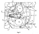
figure 5 représente une vue de dessus de lafigure 4 lorsque l'un des poussoirs est actionné et que sa tige de commande est en course maximum. - La
figure 6 représente une vue de dessus de lafigure 5 lorsque le cadran rotatif est en cours de rotation. - La
figure 7 représente une vue de dessus de lafigure 4 lorsque les deux poussoirs sont actionnés simultanément. - Selon le mode d'exécution principal de la présente Invention, le module horloger comporte le cadran rotatif (1) comprenant l'ouverture (2). Ledit cadran (1) est agencé de manière rotative sur le cadran de base (3) par l'intermédiaire d'un roulement à bille (4). Le cadran de base (3) comporte quatre ouvertures (5) positionnées chacune à 90 degrés destinées à laisser apparaître quatre complications du mouvement horloger.
- Le cadran rotatif (1) comporte sur la face inférieure d'une part un élément annulaire (6) en son centre sur lequel sont positionnées à intervalle régulier les quatre goupilles d'entraînement (7) et d'autre part les quatre autres goupilles de butées (8) positionnées en sa périphérie également à intervalle régulier, ceci en correspondance avec les goupilles d'entraînement (7).
- Chacune des quatre goupilles d'entraînement (7) est destinée à être entraînée par un mécanisme instantané, qui sera décrit ultérieurement, afin d'assurer la rotation du cadran rotatif (1) de 90 degrés lorsqu'un poussoir (9, 9') est actionné. Chacune des goupilles de butées (8) est quant à elle destinée à stopper la rotation du cadran rotatif (1) lorsque celui-ci a effectué une rotation de 90 degrés.
- Dans la mesure où le module horloger comporte deux systèmes de commande identiques placés de façon symétrique par rapport à l'axe 3H/9H, l'un entraînant la rotation du cadran rotatif (1) dans le sens horaire et l'autre l'entraînant dans le sens antihoraire, seule l'action de l'un de ces systèmes sera décrite.
- Le système de commande qui a pour but de faire pivoter le cadran rotatif (1) du module dans le sens horaire comporte les séquences suivantes :
- le poussoir (9) actionne une bascule de transmission (10) qui transmet un mouvement rectiligne à une tige (11) jusqu'à ce que l'une de ses extrémités actionne une bascule dite de butée (12) ;
- sous l'action de ladite tige (11), cette bascule (12), qui comporte un doigt d'arrêt (13) pouvant librement basculer autour d'un axe de rotation (14) entre deux goupilles (15) limitant le débattement du doigt (13), pivote afin de désengager momentanément le doigt d'arrêt (13) d'une des goupilles de butées (8) (
Figure 5 ) ; - sous l'action d'un ressort de rappel (16) agencé sur la tige (11), celle-ci est animée d'un mouvement rectiligne opposé lorsque le poussoir (9) n'est plus actionné, ce qui amène un crochet (17) solidaire de la tige (11) en contact avec l'une des goupilles d'entraînement (7);
- sous l'impulsion du ressort de rappel (16) le crochet (17) entraîne la goupille d'entraînement (7) occasionnant ainsi la rotation du cadran rotatif (1) dans le sens horaire (
Figure 6 ) ; - la tige (11) retourne ensuite dans sa position de repos ;
- à ce moment, sous l'action d'une lame ressort (18), la bascule de butée (12) a repris sa position initiale permettant ainsi l'arrêt de la prochaine goupille de butée (8) par le doigt d'arrêt (13) lorsque le cadran rotatif (1) aura pivoté de 90 degrés.
- Lorsqu'il est actionné, le poussoir (9) enclenche la rotation instantanée du cadran rotatif (1) par le biais des diverses séquences susmentionnées, Cependant, lorsque l'une des goupilles de butées (8) est stoppée par le doigt d'arrêt (13), le cadran rotatif (1), ayant effectué une rotation de 90 degrés, se retrouve dans une position instable, Pour palier à ce problème, le cadran rotatif (1) comporte sur son pourtour quatre bossages (19) associés aux goupilles de butées (8). Ceux-ci sont destinés à venir se positionner à tour de rôle dans un logement (20) situés sur une lame ressort (21) assurant ainsi la stabilité du cadran rotatif (1). Cette lame ressort (21) est agencée dans un dégagement (non illustré) se trouvant dans le cadran de base (3).
- Ce dernier comporte une ouverture (22) (
Figure 1 ) supplémentaire à 10H afin de positionner le doigt (13) de la bascule dite de butée (12) au niveau des goupilles de butée (8). - Le crochet (17) est librement ajusté sur la tige (11) autour d'un axe (23) perpendiculaire à cette dernière (
Figure 3 ). Un ressort (24) est vissé sur ladite tige (11) de sorte que l'une de ses extrémités appuie sur le talon du crochet (17) forçant sa position en saillie à 90 degrés par rapport à la tige (11). Le crochet (17) peut ainsi se rabattre au contact d'une des quatre goupils d'entraînement (7) évitant ainsi le blocage de la tige (11) lorsque le poussoir (9) est actionné. - Les divers éléments constitutifs du système de commande décrit ci-dessus et du système de commande qui a pour but de faire pivoter le cadran rotatif (1) du module dans le sens antihoraire par l'action d'un poussoir (9') sont agencés sur une platine (24) qui est destinée à être positionnée directement sur le mouvement horloger. Ladite platine (24) comporte des ouvertures (25) en correspondance avec les ouvertures (5) du cadran de base (3) afin de laisser apparaître les quatre complications du mouvement horloger.
- La forme et le positionnement de manière symétrique des deux bascules de transmission (10, 10') permettent d'actionner uniquement un poussoir (9, 9') à la fois, une pression simultanée sur lesdits poussoirs bloquant les deux systèmes de commande (
Figure 7 ). - Le mode de réalisation n'est nullement limitatif et par conséquent le nombre de goupilles d'entraînement et de butée (7, 8) peut être inférieur ou supérieur à quatre afin de varier l'angle de rotation du cadran rotatif (1) lorsque le poussoir (9) est actionné. Les intervalles entre lesdites goupilles d'entraînements et de butée (7, 8) peut ne pas être régulier. Par ailleurs, des motifs peuvent remplacer une ou plusieurs complications du mouvement horloger.
Claims (11)
- Module horloger agencé pour être ajusté sur un mouvement horloger, ledit module comportant un cadran rotatif (1) comprenant une ouverture (2) agencée pour permettre de visualiser une complication du mouvement horloger ou une image, caractérisé en ce que ledit cadran rotatif (1) est monté de manière rotative sur un cadran de base (3) par l'intermédiaire d'un organe annulaire à basse friction (4), un poussoir (9) pouvant faire pivoter d'un certain angle ledit cadran rotatif (1) de manière à pouvoir visualiser une autre complication ou image à travers l'ouverture (2).
- Module horloger selon la revendication 1, caractérisé en ce qu'il comporte des moyens (8, 13,19, 21) pour stopper et solidariser le cadran rotatif (1) au cadran de base (3), ledit module étant agencé d'une part de manière à désolidariser le cadran rotatif (1) au cadran de base (3) lorsque le poussoir (9, 9') est poussé et d'autre part pour entraîner le cadran rotatif (1) lorsque le poussoir (9,9') est relâché.
- Module horloger selon la revendication 2, caractérisé en ce que le cadran rotatif (1) comporte sur sa face inférieure d'une part plusieurs goupilles dites d'entraînement (7) agencées à intervalle régulier ou non sur un cercle (6) situé proche de son centre et d'autre part plusieurs goupilles dites de butée (8) positionnées en sa périphérie à intervalle régulier ou non, l'action du poussoir (9) faisant pivoter une bascule de transmission (10) qui communique un mouvement rectiligne à une tige (11) jusqu'à ce que l'une de ses extrémités actionne une bascule dite de butée (12) comportant des moyens d'arrêt des goupilles de butée (8), la bascule de butée (12) pivotant afin de désengager momentanément l'une desdites goupilles de butées (8) desdits moyens d'arrêt, ladite tige (11) comportant un ressort de rappel (16) lui permettant de regagner sa position de repos lorsque le poussoir (9) n'est plus actionné, la tige (11) entraînant sur son passage l'une des goupilles d'entraînement (7) par l'intermédiaire d'un crochet (17) déclenchant ainsi la rotation dans un premier sens de rotation du cadran rotatif (1), celui-ci pivotant jusqu'à ce que la prochaine goupille de butée (8) est arrêtée par les moyens d'arrêt de la bascule de butée (12).
- Module horloger selon la revendication 3, caractérisé en ce qu'elle comprend un second poussoir (9') faisant pivoter une seconde bascule de transmission (10') lorsque le second poussoir (9') est actionné, ladite seconde bascule (10') transmettant un mouvement rectiligne à une seconde tige (11') jusqu'à ce que l'une de ces extrémités actionne la bascule de butée (12), ladite seconde tige (11') comportant un second ressort de rappel (16') lui permettant de regagner sa position de repos lorsque le second poussoir (9') n'est plus actionné tout en entraînant sur son passage l'une des goupilles d'entraînement (7) par l'intermédiaire d'un second crochet (17') déclenchant ainsi la rotation dans le sens opposé audit premier sens du cadran rotatif (1).
- Module horloger selon la revendication 4, caractérisé en ce que la forme et le positionnement des deux bascules de transmission (10, 10') permettent d'actionner uniquement un poussoir (9, 9') à la fois.
- Module horloger selon l'une quelconque des revendications 3 à 5, caractérisé en ce que les moyens d'arrêt de la bascule de butée (12) comporte un doigt d'arrêt (13) pouvant librement basculer autour d'un axe de rotation (14) et deux goupilles (15) limitant le débattement dudit doigt (13).
- Module horloger selon la revendication 6, caractérisé en ce que le pourtour du cadran rotatif (1) comporte plusieurs bossages (19) destinés à s'ajuster à tour de rôle dans un logement (20) situé sur une lame ressort (21) lorsque l'une des goupilles de butée (8) est arrêtée par le doigt d'arrêt (13) assurant ainsi le maintien du cadran rotatif dans une position fixe.
- Module horloger selon la revendication 4, caractérisé en ce que chaque crochet (17, 17') est librement ajusté sur sa tige (11, 11') autour d'un axe (23, 23') perpendiculaire à cette dernière, un ressort (24, 24') étant fixé sur la tige (11, 11') de sorte qu'il appuie sur le talon du crochet (17, 17') forçant sa position en saillie par rapport à la tige (11, 11'), le crochet (17, 17') se rabattant au contact de la goupille d'entraînement (7) lorsque la tige (11, 11') est actionnée par la bascule de transmission (10, 10').
- Module horloger selon la revendication 7, caractérisé en ce que les goupilles d'entraînement (7), les goupilles de butées (8) et le cas échéant les bossages (19) sont en nombre égale et positionnés en correspondance.
- Module horloger selon la revendication 9, caractérisé en ce qu'elle comporte quatre goupilles d'entraînement (7), quatre goupilles de butées (8) et quatre bossages (19).
- Montre comportant le module horloger selon l'une quelconque des revendications 1 à 10.
Priority Applications (4)
| Application Number | Priority Date | Filing Date | Title |
|---|---|---|---|
| EP06006515A EP1840680B1 (fr) | 2006-03-29 | 2006-03-29 | Module horloger comportant un cadran rotatif ajustable sur un mouvement horloger |
| AT06006515T ATE399338T1 (de) | 2006-03-29 | 2006-03-29 | Uhrmodul, das ein verstellbares drehbares zifferblatt auf einem uhrwerk umfasst |
| DE602006001574T DE602006001574D1 (de) | 2006-03-29 | 2006-03-29 | Uhrmodul, das ein verstellbares drehbares Zifferblatt auf einem Uhrwerk umfasst |
| US11/689,920 US7551522B2 (en) | 2006-03-29 | 2007-03-22 | Watch module comprising a rotary dial capable of being fitted to a watch movement |
Applications Claiming Priority (1)
| Application Number | Priority Date | Filing Date | Title |
|---|---|---|---|
| EP06006515A EP1840680B1 (fr) | 2006-03-29 | 2006-03-29 | Module horloger comportant un cadran rotatif ajustable sur un mouvement horloger |
Publications (2)
| Publication Number | Publication Date |
|---|---|
| EP1840680A1 EP1840680A1 (fr) | 2007-10-03 |
| EP1840680B1 true EP1840680B1 (fr) | 2008-06-25 |
Family
ID=37682673
Family Applications (1)
| Application Number | Title | Priority Date | Filing Date |
|---|---|---|---|
| EP06006515A Expired - Lifetime EP1840680B1 (fr) | 2006-03-29 | 2006-03-29 | Module horloger comportant un cadran rotatif ajustable sur un mouvement horloger |
Country Status (4)
| Country | Link |
|---|---|
| US (1) | US7551522B2 (fr) |
| EP (1) | EP1840680B1 (fr) |
| AT (1) | ATE399338T1 (fr) |
| DE (1) | DE602006001574D1 (fr) |
Cited By (3)
| Publication number | Priority date | Publication date | Assignee | Title |
|---|---|---|---|---|
| EP2503408A1 (fr) | 2011-03-22 | 2012-09-26 | De Grisogono S.A. | Dispositif de commande pour mouvement horloger |
| EP2503406A1 (fr) | 2011-03-22 | 2012-09-26 | De Grisogono S.A. | Dispositif amortisseur pour mecanisme horloger |
| EP2503403A1 (fr) | 2011-03-22 | 2012-09-26 | De Grisogono S.A. | Dispositif de securité pour barillet de mouvement horloger |
Families Citing this family (4)
| Publication number | Priority date | Publication date | Assignee | Title |
|---|---|---|---|---|
| JPH0640945A (ja) * | 1992-07-23 | 1994-02-15 | Kureha Chem Ind Co Ltd | Fcフラグメント結合抗腫瘍剤 |
| EP2317408B1 (fr) | 2009-10-27 | 2012-09-12 | Télôs Watch SA | Pièce d'horlogerie |
| EP2365404A1 (fr) * | 2010-03-12 | 2011-09-14 | The Swatch Group Research and Development Ltd. | Cadran au moins partiellement émaillé en relief |
| US12078966B2 (en) * | 2019-07-25 | 2024-09-03 | Casio Computer Co., Ltd. | Dial, module, electronic device and timepiece |
Family Cites Families (8)
| Publication number | Priority date | Publication date | Assignee | Title |
|---|---|---|---|---|
| CH338782A (de) * | 1955-09-08 | 1959-05-31 | Seemann Wolfgang | Zeitmesser |
| US4206592A (en) * | 1970-03-30 | 1980-06-10 | Maue Marilyn J | Timepiece for identifying time by color |
| US4006588A (en) * | 1975-11-19 | 1977-02-08 | Mcmahon Robert J | Wrist watch |
| FR2626985A1 (fr) * | 1988-02-05 | 1989-08-11 | Huber Michel | Piece d'horlogerie comportant des premier et deuxieme dispositifs d'affichage |
| US5044961A (en) * | 1990-10-16 | 1991-09-03 | Eileen Bruskewitz | Child activity timer |
| US5088440A (en) * | 1990-12-28 | 1992-02-18 | Keaney Carl J | Indicator for an indicating device |
| EP0652496B1 (fr) * | 1993-05-21 | 1999-07-21 | Seiko Epson Corporation | Cadran de chronographe et chronographe |
| US6744695B2 (en) * | 2001-11-20 | 2004-06-01 | Alex Goldberg | Planisphere watch |
-
2006
- 2006-03-29 EP EP06006515A patent/EP1840680B1/fr not_active Expired - Lifetime
- 2006-03-29 DE DE602006001574T patent/DE602006001574D1/de not_active Expired - Fee Related
- 2006-03-29 AT AT06006515T patent/ATE399338T1/de not_active IP Right Cessation
-
2007
- 2007-03-22 US US11/689,920 patent/US7551522B2/en not_active Expired - Fee Related
Cited By (3)
| Publication number | Priority date | Publication date | Assignee | Title |
|---|---|---|---|---|
| EP2503408A1 (fr) | 2011-03-22 | 2012-09-26 | De Grisogono S.A. | Dispositif de commande pour mouvement horloger |
| EP2503406A1 (fr) | 2011-03-22 | 2012-09-26 | De Grisogono S.A. | Dispositif amortisseur pour mecanisme horloger |
| EP2503403A1 (fr) | 2011-03-22 | 2012-09-26 | De Grisogono S.A. | Dispositif de securité pour barillet de mouvement horloger |
Also Published As
| Publication number | Publication date |
|---|---|
| US7551522B2 (en) | 2009-06-23 |
| ATE399338T1 (de) | 2008-07-15 |
| EP1840680A1 (fr) | 2007-10-03 |
| US20070230287A1 (en) | 2007-10-04 |
| DE602006001574D1 (de) | 2008-08-07 |
Similar Documents
| Publication | Publication Date | Title |
|---|---|---|
| EP1342131B1 (fr) | Boîte de montre | |
| EP2073076B1 (fr) | Mécanisme de commande d'un réveil | |
| EP1962155B1 (fr) | Montre chronographe | |
| EP2073079A2 (fr) | Mécanisme de chronographe, mouvement horloger et pièce d'horlogerie comprenant un tel mécanisme | |
| CH706021B1 (fr) | Mouvement horloger du type chronographe à rattrapante et pièce d'horlogerie munie d'un tel mouvement. | |
| EP1840680B1 (fr) | Module horloger comportant un cadran rotatif ajustable sur un mouvement horloger | |
| EP1962152A1 (fr) | Dispositif de sécurité pour affichage | |
| EP3542227B1 (fr) | Dispositif indicateur de fuseaux horaires | |
| EP1706795B1 (fr) | Montre munie de poussoirs comportant un mecanisme d'actionnement d'organes de commande délocalisés d'un mouvement d'horlogerie | |
| EP3644130B1 (fr) | Mecanisme de quantieme | |
| CH709539A2 (fr) | Dispositif d'affichage. | |
| EP4462192B1 (fr) | Dispositif d'affichage pour mouvement horloger | |
| WO2006058925A2 (fr) | Piece d'horlogerie a animation | |
| EP2643735A1 (fr) | Mecanisme d'affichage pour piece d'horlogerie | |
| EP4361739A1 (fr) | Système de sélection de fonction pour montre | |
| EP3330807B1 (fr) | Dispositif d'affichage alternatif | |
| EP2477080A1 (fr) | Pièce d'horlogerie à indication du fuseau horaire correspondant à une heure choisie | |
| EP2249215A2 (fr) | Montre-chronographe à affichage instantané de fractions de seconde | |
| EP3714336B1 (fr) | Maintien d'un mobile portant un disque d'affichage | |
| CH719079A2 (fr) | Dispositif horloger à montage simplifié. | |
| CH709538B1 (fr) | Pièce d'horlogerie. | |
| CH712736B1 (fr) | Dispositif d'affichage horloger à guichet mobile. | |
| CH713141A2 (fr) | Dispositif indicateur de fuseaux horaires. | |
| CH716150B1 (fr) | Mécanisme horloger de blocage d'un mobile sautant et mouvement pour montre chronographe le comprenant. | |
| FR3064084A1 (fr) | Montre a cadran rotatif et utilisation ambidextre |
Legal Events
| Date | Code | Title | Description |
|---|---|---|---|
| PUAI | Public reference made under article 153(3) epc to a published international application that has entered the european phase |
Free format text: ORIGINAL CODE: 0009012 |
|
| 17P | Request for examination filed |
Effective date: 20070228 |
|
| AK | Designated contracting states |
Kind code of ref document: A1 Designated state(s): AT BE BG CH CY CZ DE DK EE ES FI FR GB GR HU IE IS IT LI LT LU LV MC NL PL PT RO SE SI SK TR |
|
| AX | Request for extension of the european patent |
Extension state: AL BA HR MK YU |
|
| GRAP | Despatch of communication of intention to grant a patent |
Free format text: ORIGINAL CODE: EPIDOSNIGR1 |
|
| GRAS | Grant fee paid |
Free format text: ORIGINAL CODE: EPIDOSNIGR3 |
|
| GRAA | (expected) grant |
Free format text: ORIGINAL CODE: 0009210 |
|
| AKX | Designation fees paid |
Designated state(s): AT BE BG CH CY CZ DE DK EE ES FI FR GB GR HU IE IS IT LI LT LU LV MC NL PL PT RO SE SI SK TR |
|
| AK | Designated contracting states |
Kind code of ref document: B1 Designated state(s): AT BE BG CH CY CZ DE DK EE ES FI FR GB GR HU IE IS IT LI LT LU LV MC NL PL PT RO SE SI SK TR |
|
| REG | Reference to a national code |
Ref country code: GB Ref legal event code: FG4D Free format text: NOT ENGLISH |
|
| REG | Reference to a national code |
Ref country code: CH Ref legal event code: EP |
|
| REF | Corresponds to: |
Ref document number: 602006001574 Country of ref document: DE Date of ref document: 20080807 Kind code of ref document: P |
|
| REG | Reference to a national code |
Ref country code: IE Ref legal event code: FG4D Free format text: LANGUAGE OF EP DOCUMENT: FRENCH |
|
| REG | Reference to a national code |
Ref country code: CH Ref legal event code: NV Representative=s name: GRIFFES CONSULTING SA |
|
| PG25 | Lapsed in a contracting state [announced via postgrant information from national office to epo] |
Ref country code: SI Free format text: LAPSE BECAUSE OF FAILURE TO SUBMIT A TRANSLATION OF THE DESCRIPTION OR TO PAY THE FEE WITHIN THE PRESCRIBED TIME-LIMIT Effective date: 20080625 Ref country code: FI Free format text: LAPSE BECAUSE OF FAILURE TO SUBMIT A TRANSLATION OF THE DESCRIPTION OR TO PAY THE FEE WITHIN THE PRESCRIBED TIME-LIMIT Effective date: 20080625 |
|
| PG25 | Lapsed in a contracting state [announced via postgrant information from national office to epo] |
Ref country code: LV Free format text: LAPSE BECAUSE OF FAILURE TO SUBMIT A TRANSLATION OF THE DESCRIPTION OR TO PAY THE FEE WITHIN THE PRESCRIBED TIME-LIMIT Effective date: 20080625 Ref country code: NL Free format text: LAPSE BECAUSE OF FAILURE TO SUBMIT A TRANSLATION OF THE DESCRIPTION OR TO PAY THE FEE WITHIN THE PRESCRIBED TIME-LIMIT Effective date: 20080625 Ref country code: PL Free format text: LAPSE BECAUSE OF FAILURE TO SUBMIT A TRANSLATION OF THE DESCRIPTION OR TO PAY THE FEE WITHIN THE PRESCRIBED TIME-LIMIT Effective date: 20080625 Ref country code: AT Free format text: LAPSE BECAUSE OF FAILURE TO SUBMIT A TRANSLATION OF THE DESCRIPTION OR TO PAY THE FEE WITHIN THE PRESCRIBED TIME-LIMIT Effective date: 20080625 |
|
| NLV1 | Nl: lapsed or annulled due to failure to fulfill the requirements of art. 29p and 29m of the patents act | ||
| PG25 | Lapsed in a contracting state [announced via postgrant information from national office to epo] |
Ref country code: SE Free format text: LAPSE BECAUSE OF FAILURE TO SUBMIT A TRANSLATION OF THE DESCRIPTION OR TO PAY THE FEE WITHIN THE PRESCRIBED TIME-LIMIT Effective date: 20080925 Ref country code: CZ Free format text: LAPSE BECAUSE OF FAILURE TO SUBMIT A TRANSLATION OF THE DESCRIPTION OR TO PAY THE FEE WITHIN THE PRESCRIBED TIME-LIMIT Effective date: 20080625 Ref country code: IS Free format text: LAPSE BECAUSE OF FAILURE TO SUBMIT A TRANSLATION OF THE DESCRIPTION OR TO PAY THE FEE WITHIN THE PRESCRIBED TIME-LIMIT Effective date: 20081025 Ref country code: LT Free format text: LAPSE BECAUSE OF FAILURE TO SUBMIT A TRANSLATION OF THE DESCRIPTION OR TO PAY THE FEE WITHIN THE PRESCRIBED TIME-LIMIT Effective date: 20080625 |
|
| PG25 | Lapsed in a contracting state [announced via postgrant information from national office to epo] |
Ref country code: SK Free format text: LAPSE BECAUSE OF FAILURE TO SUBMIT A TRANSLATION OF THE DESCRIPTION OR TO PAY THE FEE WITHIN THE PRESCRIBED TIME-LIMIT Effective date: 20080625 Ref country code: RO Free format text: LAPSE BECAUSE OF FAILURE TO SUBMIT A TRANSLATION OF THE DESCRIPTION OR TO PAY THE FEE WITHIN THE PRESCRIBED TIME-LIMIT Effective date: 20080625 Ref country code: ES Free format text: LAPSE BECAUSE OF FAILURE TO SUBMIT A TRANSLATION OF THE DESCRIPTION OR TO PAY THE FEE WITHIN THE PRESCRIBED TIME-LIMIT Effective date: 20081006 Ref country code: PT Free format text: LAPSE BECAUSE OF FAILURE TO SUBMIT A TRANSLATION OF THE DESCRIPTION OR TO PAY THE FEE WITHIN THE PRESCRIBED TIME-LIMIT Effective date: 20081125 |
|
| REG | Reference to a national code |
Ref country code: IE Ref legal event code: FD4D |
|
| PG25 | Lapsed in a contracting state [announced via postgrant information from national office to epo] |
Ref country code: EE Free format text: LAPSE BECAUSE OF FAILURE TO SUBMIT A TRANSLATION OF THE DESCRIPTION OR TO PAY THE FEE WITHIN THE PRESCRIBED TIME-LIMIT Effective date: 20080625 Ref country code: IE Free format text: LAPSE BECAUSE OF FAILURE TO SUBMIT A TRANSLATION OF THE DESCRIPTION OR TO PAY THE FEE WITHIN THE PRESCRIBED TIME-LIMIT Effective date: 20080625 Ref country code: BG Free format text: LAPSE BECAUSE OF FAILURE TO SUBMIT A TRANSLATION OF THE DESCRIPTION OR TO PAY THE FEE WITHIN THE PRESCRIBED TIME-LIMIT Effective date: 20080925 Ref country code: DK Free format text: LAPSE BECAUSE OF FAILURE TO SUBMIT A TRANSLATION OF THE DESCRIPTION OR TO PAY THE FEE WITHIN THE PRESCRIBED TIME-LIMIT Effective date: 20080625 |
|
| PLBE | No opposition filed within time limit |
Free format text: ORIGINAL CODE: 0009261 |
|
| STAA | Information on the status of an ep patent application or granted ep patent |
Free format text: STATUS: NO OPPOSITION FILED WITHIN TIME LIMIT |
|
| 26N | No opposition filed |
Effective date: 20090326 |
|
| BERE | Be: lapsed |
Owner name: DE GRISOGONO S.A. Effective date: 20090331 |
|
| PG25 | Lapsed in a contracting state [announced via postgrant information from national office to epo] |
Ref country code: MC Free format text: LAPSE BECAUSE OF NON-PAYMENT OF DUE FEES Effective date: 20090331 |
|
| PG25 | Lapsed in a contracting state [announced via postgrant information from national office to epo] |
Ref country code: DE Free format text: LAPSE BECAUSE OF NON-PAYMENT OF DUE FEES Effective date: 20091001 |
|
| PG25 | Lapsed in a contracting state [announced via postgrant information from national office to epo] |
Ref country code: BE Free format text: LAPSE BECAUSE OF NON-PAYMENT OF DUE FEES Effective date: 20090331 |
|
| PG25 | Lapsed in a contracting state [announced via postgrant information from national office to epo] |
Ref country code: GR Free format text: LAPSE BECAUSE OF FAILURE TO SUBMIT A TRANSLATION OF THE DESCRIPTION OR TO PAY THE FEE WITHIN THE PRESCRIBED TIME-LIMIT Effective date: 20080926 |
|
| PG25 | Lapsed in a contracting state [announced via postgrant information from national office to epo] |
Ref country code: LU Free format text: LAPSE BECAUSE OF NON-PAYMENT OF DUE FEES Effective date: 20090329 |
|
| PG25 | Lapsed in a contracting state [announced via postgrant information from national office to epo] |
Ref country code: HU Free format text: LAPSE BECAUSE OF FAILURE TO SUBMIT A TRANSLATION OF THE DESCRIPTION OR TO PAY THE FEE WITHIN THE PRESCRIBED TIME-LIMIT Effective date: 20081226 |
|
| PG25 | Lapsed in a contracting state [announced via postgrant information from national office to epo] |
Ref country code: TR Free format text: LAPSE BECAUSE OF FAILURE TO SUBMIT A TRANSLATION OF THE DESCRIPTION OR TO PAY THE FEE WITHIN THE PRESCRIBED TIME-LIMIT Effective date: 20080625 |
|
| PG25 | Lapsed in a contracting state [announced via postgrant information from national office to epo] |
Ref country code: CY Free format text: LAPSE BECAUSE OF FAILURE TO SUBMIT A TRANSLATION OF THE DESCRIPTION OR TO PAY THE FEE WITHIN THE PRESCRIBED TIME-LIMIT Effective date: 20080625 |
|
| PGFP | Annual fee paid to national office [announced via postgrant information from national office to epo] |
Ref country code: CH Payment date: 20140319 Year of fee payment: 9 |
|
| PGFP | Annual fee paid to national office [announced via postgrant information from national office to epo] |
Ref country code: FR Payment date: 20140319 Year of fee payment: 9 |
|
| PGFP | Annual fee paid to national office [announced via postgrant information from national office to epo] |
Ref country code: GB Payment date: 20140319 Year of fee payment: 9 |
|
| PGFP | Annual fee paid to national office [announced via postgrant information from national office to epo] |
Ref country code: IT Payment date: 20140331 Year of fee payment: 9 |
|
| REG | Reference to a national code |
Ref country code: CH Ref legal event code: PL |
|
| GBPC | Gb: european patent ceased through non-payment of renewal fee |
Effective date: 20150329 |
|
| PG25 | Lapsed in a contracting state [announced via postgrant information from national office to epo] |
Ref country code: IT Free format text: LAPSE BECAUSE OF NON-PAYMENT OF DUE FEES Effective date: 20150329 |
|
| REG | Reference to a national code |
Ref country code: FR Ref legal event code: ST Effective date: 20151130 |
|
| PG25 | Lapsed in a contracting state [announced via postgrant information from national office to epo] |
Ref country code: CH Free format text: LAPSE BECAUSE OF NON-PAYMENT OF DUE FEES Effective date: 20150331 Ref country code: GB Free format text: LAPSE BECAUSE OF NON-PAYMENT OF DUE FEES Effective date: 20150329 Ref country code: LI Free format text: LAPSE BECAUSE OF NON-PAYMENT OF DUE FEES Effective date: 20150331 |
|
| PG25 | Lapsed in a contracting state [announced via postgrant information from national office to epo] |
Ref country code: FR Free format text: LAPSE BECAUSE OF NON-PAYMENT OF DUE FEES Effective date: 20150331 |