EP1852214A1 - Dispositif de serrage d'une pièce, muni d'un porte-outil - Google Patents
Dispositif de serrage d'une pièce, muni d'un porte-outil Download PDFInfo
- Publication number
- EP1852214A1 EP1852214A1 EP07008276A EP07008276A EP1852214A1 EP 1852214 A1 EP1852214 A1 EP 1852214A1 EP 07008276 A EP07008276 A EP 07008276A EP 07008276 A EP07008276 A EP 07008276A EP 1852214 A1 EP1852214 A1 EP 1852214A1
- Authority
- EP
- European Patent Office
- Prior art keywords
- tool
- workpiece
- machining
- holding device
- clamping
- Prior art date
- Legal status (The legal status is an assumption and is not a legal conclusion. Google has not performed a legal analysis and makes no representation as to the accuracy of the status listed.)
- Granted
Links
- 238000000034 method Methods 0.000 claims abstract description 6
- 230000000284 resting effect Effects 0.000 claims abstract description 3
- 238000003754 machining Methods 0.000 claims description 28
- 230000008878 coupling Effects 0.000 claims description 17
- 238000010168 coupling process Methods 0.000 claims description 17
- 238000005859 coupling reaction Methods 0.000 claims description 17
- 238000003801 milling Methods 0.000 claims description 6
- 238000003860 storage Methods 0.000 claims description 6
- 238000005520 cutting process Methods 0.000 abstract description 3
- 210000000078 claw Anatomy 0.000 description 5
- 239000012530 fluid Substances 0.000 description 2
- 239000007822 coupling agent Substances 0.000 description 1
- 238000004519 manufacturing process Methods 0.000 description 1
- 238000000465 moulding Methods 0.000 description 1
Images


Classifications
-
- B—PERFORMING OPERATIONS; TRANSPORTING
- B23—MACHINE TOOLS; METAL-WORKING NOT OTHERWISE PROVIDED FOR
- B23Q—DETAILS, COMPONENTS, OR ACCESSORIES FOR MACHINE TOOLS, e.g. ARRANGEMENTS FOR COPYING OR CONTROLLING; MACHINE TOOLS IN GENERAL CHARACTERISED BY THE CONSTRUCTION OF PARTICULAR DETAILS OR COMPONENTS; COMBINATIONS OR ASSOCIATIONS OF METAL-WORKING MACHINES, NOT DIRECTED TO A PARTICULAR RESULT
- B23Q7/00—Arrangements for handling work specially combined with or arranged in, or specially adapted for use in connection with, machine tools, e.g. for conveying, loading, positioning, discharging, sorting
- B23Q7/14—Arrangements for handling work specially combined with or arranged in, or specially adapted for use in connection with, machine tools, e.g. for conveying, loading, positioning, discharging, sorting co-ordinated in production lines
- B23Q7/1426—Arrangements for handling work specially combined with or arranged in, or specially adapted for use in connection with, machine tools, e.g. for conveying, loading, positioning, discharging, sorting co-ordinated in production lines with work holders not rigidly fixed to the transport devices
-
- B—PERFORMING OPERATIONS; TRANSPORTING
- B23—MACHINE TOOLS; METAL-WORKING NOT OTHERWISE PROVIDED FOR
- B23B—TURNING; BORING
- B23B5/00—Turning-machines or devices specially adapted for particular work; Accessories specially adapted therefor
- B23B5/36—Turning-machines or devices specially adapted for particular work; Accessories specially adapted therefor for turning specially-shaped surfaces by making use of relative movement of the tool and work produced by geometrical mechanisms, i.e. forming-lathes
- B23B5/40—Turning-machines or devices specially adapted for particular work; Accessories specially adapted therefor for turning specially-shaped surfaces by making use of relative movement of the tool and work produced by geometrical mechanisms, i.e. forming-lathes for turning spherical surfaces inside or outside
-
- B—PERFORMING OPERATIONS; TRANSPORTING
- B23—MACHINE TOOLS; METAL-WORKING NOT OTHERWISE PROVIDED FOR
- B23Q—DETAILS, COMPONENTS, OR ACCESSORIES FOR MACHINE TOOLS, e.g. ARRANGEMENTS FOR COPYING OR CONTROLLING; MACHINE TOOLS IN GENERAL CHARACTERISED BY THE CONSTRUCTION OF PARTICULAR DETAILS OR COMPONENTS; COMBINATIONS OR ASSOCIATIONS OF METAL-WORKING MACHINES, NOT DIRECTED TO A PARTICULAR RESULT
- B23Q3/00—Devices holding, supporting, or positioning work or tools, of a kind normally removable from the machine
- B23Q3/155—Arrangements for automatic insertion or removal of tools, e.g. combined with manual handling
Definitions
- the invention relates to a device for machining, in particular machining of workpieces in machine tools.
- the invention relates to a device for processing differential housings in machining centers.
- the DE 41 42 121 A1 a tact line with individual processing stations, each having at least one machining spindle for performing a machining on a workpiece.
- the tact line is used for processing also called “differential carrier” or “differential gear housing” differential housings of motor vehicle differential gears.
- the document mentions both a workpiece transfer, in which the workpieces are clamped on pallets, as well as a so-called device-free transfer, in which the differential housings from processing station to processing station are given without a separate device on.
- the individual processing stations are each set up for specific operations.
- the tact line in the specifically designed form is only suitable for processing differential housings. If other workpieces are to be processed, extensive retooling measures are required.
- Compensating housings are hollow workpieces that are to be machined on their inner surfaces.
- the disclosed DE 41 04 474 C1 a tool that is equipped with a taper shank for attachment in a work spindle. His cutting tool is pivotally mounted on the tool body, wherein the pivoting movement is effected by an adjusting rod.
- Deviating areas can not or only with difficulty be processed.
- the DE 102 39 270 A1 discloses an apparatus for processing differential housings with a countersinking tool to be inserted into the interior of the differential housing.
- the countersink has frontally open coupling openings in the two motor-driven, axially displaceable drive mandrels can be inserted, which are rotatably inserted from opposite end faces with a coupling tip in the coupling openings.
- the device provided according to the invention also contains a tool, which is carried by the base at least when it is at rest. If necessary, it can be transferred to a work spindle of the machine tool, for example in the form of a machining center. Because the tool is on the apparatus is provided, on the machine tool (the machining center) no special in particular no unusual bambooshunt required for the machining operation. Therefore, both small and very small series as well as large series are editable. It is possible to work with mixed lots, where in a machining center completely different workpieces, such as differential housing and other machine parts, such as crankshafts are processed.
- the tool is supported on the base by a positioning device, by means of which the tool is held movably between a rest position and a working position.
- the positioning device may include a fluid-actuated or an electromotive drive device and be designed, for example, as a linear positioning device.
- the tool can in the interior of the example, designed as a hollow body workpiece, for. in the form of a differential housing and retracted.
- the holding means is preferably adapted to hold the tool in the rest position while, after having transferred the tool to the working position and e.g. is coupled to a work spindle releases. It can then return to its rest position while the tool remains in working position. As a result, the positioning device does not hinder the machining operation to be performed by the tool.
- the tool is preferably designed for machining and, for example, designed as a milling tool. It can be a face milling cutter, a curved surface milling cutter, a countersinking tool or the like. This can be both flat, arranged in the interior of a differential housing bearing surfaces as well as spherical or otherwise curved surfaces, eg as support or bearing surfaces for the planets of the differential gear can be edited.
- the tool is preferably provided with a coupling device for coupling the tool within the workpiece to a work spindle of the machine tool.
- the coupling device may be a positive fit, to which an adapter can be connected.
- the positive fit creates in particular a rotationally fixed connection between the adapter and the tool.
- the coupling device preferably provides a backlash-free fit of the tool to the adapter to ensure that the tool is guided by the work spindle during the machining of the workpiece.
- the adapter may also be adapted to support the tool on the workpiece, in particular to store. For example, it may have a non-round or round, for example. Cylindrical shaft which projects through a bore of the workpiece and is supported on the wall thereof.
- the bore may be a transverse bore or an axial bore of the differential housing.
- the diameter of the adapter shaft is matched to the diameter of the bore.
- the device also includes a counter-holding device to axially support the tool with respect to its axis of rotation.
- the counter-holding device can be held axially adjustable by a rotatably mounted spindle, which is provided on the device.
- a rotatably mounted spindle which is provided on the device.
- the device preferably has a multiplicity of fluid actuated actuators, for example for actuating holding devices, which clamp the workpiece at least during processing. Further actuators may be provided for this, the counter-holding device and the positioning device to steer for the tool.
- appropriate media such as compressed air and / or hydraulic fluid, and given and, if necessary, electrical supply line or measuring lines appropriate coupling means are preferably provided to supply the device in the machine tool with the required media and connect to external devices can.
- the machine tool 1 shows a machine tool 1 is illustrated, which is designed in the manner of a machining center. The enclosure of the working space is left out in the drawing.
- the machine tool 1 has at least one table 2, on which a device 3 can be placed, which holds the workpiece 4.
- the device 3 forms a self-contained module that can be transported together with the workpiece 4 by various processing stations. Alternatively, it is possible to leave the device 3 in the machine tool 1 and to use only the workpiece 4 for processing in the device 3.
- the device 3 is preferably placed resting in the machine tool 1.
- the table 2 may also be provided with means to move the device 3 in one or more directions.
- To the machine tool 1 further includes at least one work spindle 5, which is movable in at least one spatial direction, preferably in a plurality of spatial directions and which is adapted to drive a tool rotationally.
- the work spindle 5 is e.g. oriented horizontally. It can also be used in other spatial directions, e.g. be oriented vertically. There may also be several e.g. be provided parallel to each other working spindles, which at the same time, e.g. are each brought into engagement with a workpiece. Thus, several identical or different workpieces can be clamped and processed simultaneously on a device.
- the workpiece 4 is in the present embodiment, a differential housing 6, which belongs to a motor vehicle differential gear.
- the differential housing 6 has a number of successive surfaces to be machined, some of which are in the space enclosed by the differential housing 6 interior.
- the surfaces to be machined include axial bores 7, 8, transverse bores 9, 10 for the planetary gears and a forming surface 11 situated in the interior of the differential housing 6, the plane Has sections and spherical sections.
- the axial bores 7, 8 are arranged coaxially to a common axis of rotation 12 and arranged in short, formed as a tubular extensions 13, 14 bearing seats.
- a flange 15 is formed, which is provided with mounting holes 16.
- the device 3 for processing the differential housing 6 in the machining center is shown separately and simplified in FIGS. 5 to 7.
- a base 17 in the form of a base plate, a skeleton, base frame or generally a support device.
- the base 17 is adapted to be connected to the table 2 of the machine tool 1.
- clamping means 18, 19 Figure 1 are provided for the differential housing 6, which form a clamping device 20 for tightening the differential housing 6 or any other workpiece 4 on the device 3.
- the clamping means 18, 19 are preferably bearing prisms for the tube extensions 13, 14 and associated clamping claws, which are connected to a suitable actuating device, such as hydraulic cylinders.
- one or more alignment devices 21 may be associated with the tensioning device 20 to provide the differential housing 6 with a desired rotational position and axial position.
- a pressure finger 22 illustrates that is to be actuated by means of a hydraulic cylinder 23 and axially pushes the differential housing 6 in a defined position before clamping.
- the differential housing 6 is preferably held in the device 3, as illustrated in FIGS. 5 to 7, with horizontal alignment of its transverse bores 9, 10.
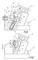
- a tool storage space 24 is preferably provided below the workpiece 4. This serves to receive and temporarily store one or two or more tools. In the present embodiment, this is illustrated for only one tool 25, which is designed as a milling tool and for machining the molding surface 11 or portions thereof.
- the tool 25 can be adjusted by a positioning device 26 at least between a rest position according to FIG. 5 and a working position in which the tool 25 is in the position according to FIG. The positioning device 26 can thus move the tool 25 out of and into the workpiece 4.
- the positioning device 26 is preferably detachably connected to the tool 25 via a gripper device 27.
- the tool 25 it is possible for the tool 25 to be movably mounted, for example rotatably, on a cantilever of the positioning device 26 and to refrain from separating the tool 25 from the positioning device 26.
- the gripping device 27 preferably includes at least two jaws 28, 29, which engage in corresponding recesses 30, 31 of the tool 5 to hold this temporarily.
- the claws 28, 29 can each form latching couplings with the recesses 30, 31, by means of which the tool 25 can be connected to and uncoupled from the positioning device 26 by the claws 28, 29 moving towards or away from the tool 25 become.
- the jaws 28, 29 are preferably pivotally mounted radially outwardly, wherein they may be biased by a spring 32 radially inwardly.
- the positioning device 26 includes, for example, a hydraulic cylinder 33 with pistons displaceably mounted therein, wherein the piston rod engages with the piston Claws 28, 29 is connected.
- the positioning device 26 may further include an imprinting device 34 provided with a finger 35 coaxial with and juxtaposed with the positioning device 26. It can serve to press the tool 25 between the jaws 28, 29 to make the locking connection between the jaws 28, 29 and the tool 25.
- Figure 8 illustrates the tool 25 within the differential housing 6 in working position.
- the claws of the positioning device 26 are released from the tool 25.
- the tool 25 is formed in this embodiment as a form cutter, which is provided with a plurality of cutting plates 36, 37.
- Its tool body 38 has corresponding plate seats.
- the tool body 38 is also provided with a bore, for example a through-bore 39, which serves for connection to the work spindle 5.
- an adapter 40 is provided in the present example, which has a cylindrical neck 41, for example, which fits through an opening of the differential housing 6, for example by its transverse bore 10.
- the neck 41 is provided at its end facing the tool 25 with a coupling means 42 for non-rotatably positive connection of the adapter 40 to the tool 25.
- the coupling agent 42 is e.g. formed by a non-circular portion of the neck 41, for example, by a hexagonal section. Accordingly, the bore 39 has a suitably shaped portion 43. In addition, it may have a cylindrical portion 44 of smaller diameter, in which a cylinder extension 45 of the adapter 40 fits.
- the neck 41 may be provided with a gripping disc 46 and a taper shank 47 or other means be, which serve to connect between the adapter 40 and the work spindle 5.
- a counter-holding device 48 e.g. be provided in the form of a support pin 49 which is held on a spindle 50 ( Figure 1).
- the spindle 50 is arranged fixed or adjustable on the device 3. Preferably, it has adjusting means for axial adjustment, so that the mandrel 49 can be retracted and extended through a suitable bore of the workpiece 4.
- the spindle 50 is preferably arranged opposite the work spindle 5.
- the work spindle 5 and the spindle 50 are thus arranged in operation coaxially with a common axis of rotation 51.
- the machine tool 1 and apparatus 3 described so far work together to machine the workpiece 4, in particular the differential housing 6, as follows:
- the differential housing 6 is inserted into the device 3, which is already in the machine tool 1 or it is transferred together with the device 3 in the machine tool 1.
- the differential housing 6 is first aligned by actuation of the corresponding alignment device (s) 21 and then tensioned.
- the clamping device 20 It can be processed in the machining center first as an ordinary workpiece. But if the inner mold surface 11 are processed in this or in another similar kind of machining center 1, the tool storage device provided in the device 3 is activated. In other words, the at least one tool 25 is moved out of the tool storage space 24 into the differential housing 6.
- the positioning device 26 is driven accordingly.
- the positioning device 26 transfers the tool 25 in a position in which its bore 39 is aligned with holes of the differential housing 6, for example with its transverse bores 9, 10 or, if the processing of the axial bores 7, 8 bounding inner surfaces is desired, aligned with the axle holes 7, 8.
- a plurality of tools (not further illustrated in FIGS. 5 to 7) can be held ready in different alignment positions in order to be retracted alternatively into the interior of the differential housing 6.
- the adapter 40 was previously used.
- the adapter 40 ride with its neck 41 and the mandrel 49 through corresponding holes (9, 10) of the differential housing and take the tool 25 between each other.
- the positive connection between the coupling means 42 (non-circular portion) and the tool 25 creates a rotationally fixed coupling between the tool 25 and the work spindle 5.
- the mandrel 49 exerts an axial pressure on the tool 25 so that it is fixed between the adapter 40 and the mandrel 49 is held.
- the mandrel 49 may for example be pneumatically or hydraulically pressurized, thus exerting in each position an axial compressive force on the adapter 40 and the work spindle 50. Each axial movement of the work spindle 50 is thus followed by the tool 25. It can now be rotationally brought to the mold surface 11 in order to process it.
- the work spindle 50 is positioned so that the jaws 28, 29 can reach the tool 25.
- the positioning device 26 and the Nachdschreib noisy 34 are now operated so that the finger 35 presses from above against the tool 25.
- the jaws 28, 29 are now pushed from below over the tool 25 and engage this one.
- the push-over device 34 can be inactivated again, ie the finger 35 can be moved out of the differential housing 6.
- the tool 25 is now free and can be moved back into the tool storage space 24.
- the processing of the mold surface 11 is thus completed or can be continued with another tool otherwise held in a similar manner by this is retracted into the interior of the differential housing 6 and connected to the work spindle 5, as described above.
- a suitable for processing of differential housings 6 in machining centers 1 device 3 has a tool storage space 24, in which at least one tool 25 is held, which is suitable for processing an inner mold surface 11 of the differential housing 6.
- the tool 25 is associated with a positioning device 26, which is also part of the device 3 and with which the tool 25 can be moved into and out of the differential housing 6.
- a corresponding adapter 40 is used, which, for example, is held in the tool magazine of the machine tool 1 or of the machining center like an ordinary tool can. It is, if necessary, replaced by a tool changing device in the work spindle 5.
Landscapes
- Engineering & Computer Science (AREA)
- Mechanical Engineering (AREA)
- Automatic Tool Replacement In Machine Tools (AREA)
- Constituent Portions Of Griding Lathes, Driving, Sensing And Control (AREA)
- Turning (AREA)
- Milling, Broaching, Filing, Reaming, And Others (AREA)
- Gear Processing (AREA)
Priority Applications (1)
| Application Number | Priority Date | Filing Date | Title |
|---|---|---|---|
| PL07008276T PL1852214T3 (pl) | 2006-05-05 | 2007-04-24 | Urządzenie do mocowania przedmiotu obrabianego z nośnikiem narzędzia |
Applications Claiming Priority (1)
| Application Number | Priority Date | Filing Date | Title |
|---|---|---|---|
| DE102006020895A DE102006020895A1 (de) | 2006-05-05 | 2006-05-05 | Werkstückspanneinrichtung mit Werkzeugträger |
Publications (2)
| Publication Number | Publication Date |
|---|---|
| EP1852214A1 true EP1852214A1 (fr) | 2007-11-07 |
| EP1852214B1 EP1852214B1 (fr) | 2008-11-12 |
Family
ID=38330704
Family Applications (1)
| Application Number | Title | Priority Date | Filing Date |
|---|---|---|---|
| EP07008276A Active EP1852214B1 (fr) | 2006-05-05 | 2007-04-24 | Dispositif de serrage d'une pièce, muni d'un porte-outil |
Country Status (5)
| Country | Link |
|---|---|
| EP (1) | EP1852214B1 (fr) |
| AT (1) | ATE413942T1 (fr) |
| DE (2) | DE102006020895A1 (fr) |
| ES (1) | ES2314956T3 (fr) |
| PL (1) | PL1852214T3 (fr) |
Cited By (2)
| Publication number | Priority date | Publication date | Assignee | Title |
|---|---|---|---|---|
| CN101456131B (zh) * | 2007-12-10 | 2010-06-16 | 河南森源电气股份有限公司 | 一种高压旋转隔离开关接地触头铣制夹具 |
| EP3718666A4 (fr) * | 2017-12-01 | 2021-07-07 | Haru Technique Laboratory Inc. | Outil de coupe pour l'usinage de boîtiers de différentiel, dispositif d'usinage de boîtier de différentiel et procédé d'usinage de boîtier de différentiel |
Families Citing this family (1)
| Publication number | Priority date | Publication date | Assignee | Title |
|---|---|---|---|---|
| DE102017125298B4 (de) | 2017-10-27 | 2024-12-19 | Gebr. Heller Maschinenfabrik Gmbh | Verfahren zum Rüsten und zum Betrieb einer Werkzeugmaschine |
Citations (2)
| Publication number | Priority date | Publication date | Assignee | Title |
|---|---|---|---|---|
| DE3243335A1 (de) * | 1982-11-19 | 1984-05-24 | Deutsche Industrieanlagen GmbH, 1000 Berlin | Flexible fertigungszelle |
| DE3707318A1 (de) * | 1987-03-07 | 1988-09-15 | Scharmann Gmbh & Co | Flexible fertigungseinrichtung mit mehreren achsparallelen nebeneinanderstehenden bearbeitungsmaschinen |
Family Cites Families (5)
| Publication number | Priority date | Publication date | Assignee | Title |
|---|---|---|---|---|
| DE4104474C1 (fr) * | 1991-02-14 | 1992-04-02 | Cross Europa-Werk Gmbh, 7317 Wendlingen, De | |
| DE4142121A1 (de) * | 1991-12-20 | 1993-06-24 | Giddings & Lewis Gmbh | Transferstrasse zur bearbeitung von werkstuecken, insbesondere zur bearbeitung von ausgleichsgehaeusen |
| DE19716491C2 (de) * | 1997-04-19 | 1999-07-29 | Chiron Werke Gmbh | Werkzeugmaschine zur Bearbeitung von Werkstückhohlräumen |
| DE10239270B4 (de) * | 2002-08-22 | 2013-10-24 | Komet Group Gmbh | Verfahren und Vorrichtung zur Innenbearbeitung von Gehäusen |
| DE10307977C5 (de) * | 2003-02-24 | 2012-04-05 | Emag Holding Gmbh | Verfahren und Vorrichtung zur Bearbeitung von Ausgleichsgehäusen |
-
2006
- 2006-05-05 DE DE102006020895A patent/DE102006020895A1/de not_active Withdrawn
-
2007
- 2007-04-24 EP EP07008276A patent/EP1852214B1/fr active Active
- 2007-04-24 ES ES07008276T patent/ES2314956T3/es active Active
- 2007-04-24 DE DE502007000229T patent/DE502007000229D1/de active Active
- 2007-04-24 PL PL07008276T patent/PL1852214T3/pl unknown
- 2007-04-24 AT AT07008276T patent/ATE413942T1/de not_active IP Right Cessation
Patent Citations (2)
| Publication number | Priority date | Publication date | Assignee | Title |
|---|---|---|---|---|
| DE3243335A1 (de) * | 1982-11-19 | 1984-05-24 | Deutsche Industrieanlagen GmbH, 1000 Berlin | Flexible fertigungszelle |
| DE3707318A1 (de) * | 1987-03-07 | 1988-09-15 | Scharmann Gmbh & Co | Flexible fertigungseinrichtung mit mehreren achsparallelen nebeneinanderstehenden bearbeitungsmaschinen |
Cited By (3)
| Publication number | Priority date | Publication date | Assignee | Title |
|---|---|---|---|---|
| CN101456131B (zh) * | 2007-12-10 | 2010-06-16 | 河南森源电气股份有限公司 | 一种高压旋转隔离开关接地触头铣制夹具 |
| EP3718666A4 (fr) * | 2017-12-01 | 2021-07-07 | Haru Technique Laboratory Inc. | Outil de coupe pour l'usinage de boîtiers de différentiel, dispositif d'usinage de boîtier de différentiel et procédé d'usinage de boîtier de différentiel |
| US11278966B2 (en) | 2017-12-01 | 2022-03-22 | Haru Technique Laboratory Inc. | Cutting tool for machining differential case, machining apparatus for differential case and machining method for differential case |
Also Published As
| Publication number | Publication date |
|---|---|
| PL1852214T3 (pl) | 2009-04-30 |
| ES2314956T3 (es) | 2009-03-16 |
| EP1852214B1 (fr) | 2008-11-12 |
| DE502007000229D1 (de) | 2008-12-24 |
| DE102006020895A1 (de) | 2007-11-08 |
| ATE413942T1 (de) | 2008-11-15 |
Similar Documents
| Publication | Publication Date | Title |
|---|---|---|
| DE10029749C2 (de) | Vorrichtung und Verfahren zum Beschicken und/oder Entnehmen von Werkstücken an einer Werkzeugmaschine | |
| DE69127513T2 (de) | Palettenspeicher- und Palettenwechselvorrichtung für WZM und Drehbank mit automatisch auswechselbaren Paletten | |
| EP1260307B1 (fr) | Machine-outil et procédé d'usinage d'une pièce en forme de barre | |
| EP3600798A1 (fr) | Système de préhension et de positionnement servant au transport d'un dispositif de serrage entre différentes positions | |
| DE102012209077B4 (de) | Spanneinrichtung zum Einspannen eines stabartigen Werkstücks und Werkzeugmaschine damit | |
| WO2014183871A1 (fr) | Machine-outil d'usinage par enlèvement de copeaux, jeu d'outils et procédé pour fabriquer un cylindre ayant un alésage borgne et/ou un alésage à gradin | |
| DE2230144C3 (de) | Werkzeugsupport mit darin lotrecht verfahrbarem Meißelschieber mit einem dem Meißelschieber zugeordneten Werkzeugwechsler | |
| DE3735858C2 (fr) | ||
| EP1884303B1 (fr) | Procédé destiné à centrer des pièces à usiner tout comme dispositif destiné à la réalisation d'un tel procédé | |
| EP1874496B1 (fr) | Dispositif de serrage | |
| EP1175278A1 (fr) | Machine-outil a manipulateur | |
| DE69620970T2 (de) | Plattensägemaschine | |
| EP1852214B1 (fr) | Dispositif de serrage d'une pièce, muni d'un porte-outil | |
| EP0480191A2 (fr) | Equipement pour l'usinage de barres | |
| EP0260692A2 (fr) | Machine-outil avec un porte-broche à forer et à fraiser à déplacement dans la direction Z sur un châssis de machine | |
| DE68927402T2 (de) | Stanz- und Nibbel-Maschine mit automatischer Werkzeugschnellwechselvorrichtung | |
| DE19936502C1 (de) | Vorrichtung und Verfahren zur schwenkbaren Werkstückzuführung in den Arbeitsbereich einer Werkzeugmaschine | |
| EP1056556B1 (fr) | Dispositif de sertissage a elements de pression et de serrage | |
| EP3431223B1 (fr) | Procédé d'usinage des pièces à usiner et machine-outil destinée à la mise en oeuvre dudit procédé | |
| DE4228708A1 (de) | Werkzeugmaschine | |
| DE69011510T2 (de) | Werkzeugmaschine, insbesondere zum Herstellen von mechanischen Teilen aus Blech wie Rollen, Räder und dergleichen. | |
| EP4536437A1 (fr) | Procédé et appareil de positionnement d'une pièce à usiner entre deux étaux | |
| EP3946950B1 (fr) | Dispositif et procédé pour remplacer des manchons sur des mandrins de cylindres ou sur des manchons d'adaptation | |
| DE2616459C2 (fr) | ||
| DE10063154B4 (de) | Schmiedepresse mit Stellvorrichtung auf Matrizenseite |
Legal Events
| Date | Code | Title | Description |
|---|---|---|---|
| PUAI | Public reference made under article 153(3) epc to a published international application that has entered the european phase |
Free format text: ORIGINAL CODE: 0009012 |
|
| AK | Designated contracting states |
Kind code of ref document: A1 Designated state(s): AT BE BG CH CY CZ DE DK EE ES FI FR GB GR HU IE IS IT LI LT LU LV MC MT NL PL PT RO SE SI SK TR |
|
| AX | Request for extension of the european patent |
Extension state: AL BA HR MK YU |
|
| 17P | Request for examination filed |
Effective date: 20080311 |
|
| GRAP | Despatch of communication of intention to grant a patent |
Free format text: ORIGINAL CODE: EPIDOSNIGR1 |
|
| AKX | Designation fees paid |
Designated state(s): AT BE BG CH CY CZ DE DK EE ES FI FR GB GR HU IE IS IT LI LT LU LV MC MT NL PL PT RO SE SI SK TR |
|
| GRAS | Grant fee paid |
Free format text: ORIGINAL CODE: EPIDOSNIGR3 |
|
| GRAA | (expected) grant |
Free format text: ORIGINAL CODE: 0009210 |
|
| AK | Designated contracting states |
Kind code of ref document: B1 Designated state(s): AT BE BG CH CY CZ DE DK EE ES FI FR GB GR HU IE IS IT LI LT LU LV MC MT NL PL PT RO SE SI SK TR |
|
| REG | Reference to a national code |
Ref country code: GB Ref legal event code: FG4D Free format text: NOT ENGLISH |
|
| REG | Reference to a national code |
Ref country code: CH Ref legal event code: EP |
|
| REG | Reference to a national code |
Ref country code: IE Ref legal event code: FG4D Free format text: LANGUAGE OF EP DOCUMENT: GERMAN |
|
| REF | Corresponds to: |
Ref document number: 502007000229 Country of ref document: DE Date of ref document: 20081224 Kind code of ref document: P |
|
| REG | Reference to a national code |
Ref country code: RO Ref legal event code: EPE |
|
| REG | Reference to a national code |
Ref country code: SE Ref legal event code: TRGR |
|
| REG | Reference to a national code |
Ref country code: ES Ref legal event code: FG2A Ref document number: 2314956 Country of ref document: ES Kind code of ref document: T3 |
|
| LTIE | Lt: invalidation of european patent or patent extension |
Effective date: 20081112 |
|
| PG25 | Lapsed in a contracting state [announced via postgrant information from national office to epo] |
Ref country code: LT Free format text: LAPSE BECAUSE OF FAILURE TO SUBMIT A TRANSLATION OF THE DESCRIPTION OR TO PAY THE FEE WITHIN THE PRESCRIBED TIME-LIMIT Effective date: 20081112 |
|
| REG | Reference to a national code |
Ref country code: PL Ref legal event code: T3 |
|
| NLV1 | Nl: lapsed or annulled due to failure to fulfill the requirements of art. 29p and 29m of the patents act | ||
| PG25 | Lapsed in a contracting state [announced via postgrant information from national office to epo] |
Ref country code: IS Free format text: LAPSE BECAUSE OF FAILURE TO SUBMIT A TRANSLATION OF THE DESCRIPTION OR TO PAY THE FEE WITHIN THE PRESCRIBED TIME-LIMIT Effective date: 20090312 Ref country code: LV Free format text: LAPSE BECAUSE OF FAILURE TO SUBMIT A TRANSLATION OF THE DESCRIPTION OR TO PAY THE FEE WITHIN THE PRESCRIBED TIME-LIMIT Effective date: 20081112 Ref country code: SI Free format text: LAPSE BECAUSE OF FAILURE TO SUBMIT A TRANSLATION OF THE DESCRIPTION OR TO PAY THE FEE WITHIN THE PRESCRIBED TIME-LIMIT Effective date: 20081112 Ref country code: NL Free format text: LAPSE BECAUSE OF FAILURE TO SUBMIT A TRANSLATION OF THE DESCRIPTION OR TO PAY THE FEE WITHIN THE PRESCRIBED TIME-LIMIT Effective date: 20081112 Ref country code: FI Free format text: LAPSE BECAUSE OF FAILURE TO SUBMIT A TRANSLATION OF THE DESCRIPTION OR TO PAY THE FEE WITHIN THE PRESCRIBED TIME-LIMIT Effective date: 20081112 |
|
| REG | Reference to a national code |
Ref country code: HU Ref legal event code: AG4A Ref document number: E005033 Country of ref document: HU |
|
| REG | Reference to a national code |
Ref country code: IE Ref legal event code: FD4D |
|
| PG25 | Lapsed in a contracting state [announced via postgrant information from national office to epo] |
Ref country code: EE Free format text: LAPSE BECAUSE OF FAILURE TO SUBMIT A TRANSLATION OF THE DESCRIPTION OR TO PAY THE FEE WITHIN THE PRESCRIBED TIME-LIMIT Effective date: 20081112 Ref country code: DK Free format text: LAPSE BECAUSE OF FAILURE TO SUBMIT A TRANSLATION OF THE DESCRIPTION OR TO PAY THE FEE WITHIN THE PRESCRIBED TIME-LIMIT Effective date: 20081112 Ref country code: IE Free format text: LAPSE BECAUSE OF FAILURE TO SUBMIT A TRANSLATION OF THE DESCRIPTION OR TO PAY THE FEE WITHIN THE PRESCRIBED TIME-LIMIT Effective date: 20081112 Ref country code: BG Free format text: LAPSE BECAUSE OF FAILURE TO SUBMIT A TRANSLATION OF THE DESCRIPTION OR TO PAY THE FEE WITHIN THE PRESCRIBED TIME-LIMIT Effective date: 20090212 |
|
| PG25 | Lapsed in a contracting state [announced via postgrant information from national office to epo] |
Ref country code: CZ Free format text: LAPSE BECAUSE OF FAILURE TO SUBMIT A TRANSLATION OF THE DESCRIPTION OR TO PAY THE FEE WITHIN THE PRESCRIBED TIME-LIMIT Effective date: 20081112 Ref country code: PT Free format text: LAPSE BECAUSE OF FAILURE TO SUBMIT A TRANSLATION OF THE DESCRIPTION OR TO PAY THE FEE WITHIN THE PRESCRIBED TIME-LIMIT Effective date: 20090413 |
|
| PLBE | No opposition filed within time limit |
Free format text: ORIGINAL CODE: 0009261 |
|
| STAA | Information on the status of an ep patent application or granted ep patent |
Free format text: STATUS: NO OPPOSITION FILED WITHIN TIME LIMIT |
|
| PG25 | Lapsed in a contracting state [announced via postgrant information from national office to epo] |
Ref country code: SK Free format text: LAPSE BECAUSE OF FAILURE TO SUBMIT A TRANSLATION OF THE DESCRIPTION OR TO PAY THE FEE WITHIN THE PRESCRIBED TIME-LIMIT Effective date: 20081112 |
|
| 26N | No opposition filed |
Effective date: 20090813 |
|
| BERE | Be: lapsed |
Owner name: GEBR. HELLER MASCHINENFABRIK G.M.B.H. Effective date: 20090430 |
|
| PG25 | Lapsed in a contracting state [announced via postgrant information from national office to epo] |
Ref country code: MC Free format text: LAPSE BECAUSE OF NON-PAYMENT OF DUE FEES Effective date: 20090430 |
|
| PG25 | Lapsed in a contracting state [announced via postgrant information from national office to epo] |
Ref country code: BE Free format text: LAPSE BECAUSE OF NON-PAYMENT OF DUE FEES Effective date: 20090430 |
|
| PGFP | Annual fee paid to national office [announced via postgrant information from national office to epo] |
Ref country code: ES Payment date: 20100426 Year of fee payment: 4 Ref country code: FR Payment date: 20100506 Year of fee payment: 4 Ref country code: HU Payment date: 20100506 Year of fee payment: 4 Ref country code: RO Payment date: 20100329 Year of fee payment: 4 |
|
| PG25 | Lapsed in a contracting state [announced via postgrant information from national office to epo] |
Ref country code: AT Free format text: LAPSE BECAUSE OF NON-PAYMENT OF DUE FEES Effective date: 20090424 |
|
| PGFP | Annual fee paid to national office [announced via postgrant information from national office to epo] |
Ref country code: DE Payment date: 20100430 Year of fee payment: 4 Ref country code: PL Payment date: 20100326 Year of fee payment: 4 |
|
| PG25 | Lapsed in a contracting state [announced via postgrant information from national office to epo] |
Ref country code: GR Free format text: LAPSE BECAUSE OF FAILURE TO SUBMIT A TRANSLATION OF THE DESCRIPTION OR TO PAY THE FEE WITHIN THE PRESCRIBED TIME-LIMIT Effective date: 20090213 |
|
| PGFP | Annual fee paid to national office [announced via postgrant information from national office to epo] |
Ref country code: SE Payment date: 20100415 Year of fee payment: 4 |
|
| PG25 | Lapsed in a contracting state [announced via postgrant information from national office to epo] |
Ref country code: LU Free format text: LAPSE BECAUSE OF NON-PAYMENT OF DUE FEES Effective date: 20090424 |
|
| PG25 | Lapsed in a contracting state [announced via postgrant information from national office to epo] |
Ref country code: TR Free format text: LAPSE BECAUSE OF FAILURE TO SUBMIT A TRANSLATION OF THE DESCRIPTION OR TO PAY THE FEE WITHIN THE PRESCRIBED TIME-LIMIT Effective date: 20081112 |
|
| PG25 | Lapsed in a contracting state [announced via postgrant information from national office to epo] |
Ref country code: CY Free format text: LAPSE BECAUSE OF FAILURE TO SUBMIT A TRANSLATION OF THE DESCRIPTION OR TO PAY THE FEE WITHIN THE PRESCRIBED TIME-LIMIT Effective date: 20081112 |
|
| REG | Reference to a national code |
Ref country code: SE Ref legal event code: EUG |
|
| REG | Reference to a national code |
Ref country code: CH Ref legal event code: PL |
|
| GBPC | Gb: european patent ceased through non-payment of renewal fee |
Effective date: 20110424 |
|
| PGFP | Annual fee paid to national office [announced via postgrant information from national office to epo] |
Ref country code: IT Payment date: 20100430 Year of fee payment: 4 |
|
| REG | Reference to a national code |
Ref country code: FR Ref legal event code: ST Effective date: 20111230 |
|
| PG25 | Lapsed in a contracting state [announced via postgrant information from national office to epo] |
Ref country code: HU Free format text: LAPSE BECAUSE OF NON-PAYMENT OF DUE FEES Effective date: 20110425 Ref country code: DE Free format text: LAPSE BECAUSE OF NON-PAYMENT OF DUE FEES Effective date: 20111101 Ref country code: LI Free format text: LAPSE BECAUSE OF NON-PAYMENT OF DUE FEES Effective date: 20110430 Ref country code: CH Free format text: LAPSE BECAUSE OF NON-PAYMENT OF DUE FEES Effective date: 20110430 Ref country code: FR Free format text: LAPSE BECAUSE OF NON-PAYMENT OF DUE FEES Effective date: 20110502 |
|
| REG | Reference to a national code |
Ref country code: DE Ref legal event code: R119 Ref document number: 502007000229 Country of ref document: DE Effective date: 20111101 |
|
| PG25 | Lapsed in a contracting state [announced via postgrant information from national office to epo] |
Ref country code: GB Free format text: LAPSE BECAUSE OF NON-PAYMENT OF DUE FEES Effective date: 20110424 |
|
| REG | Reference to a national code |
Ref country code: ES Ref legal event code: FD2A Effective date: 20120524 |
|
| PG25 | Lapsed in a contracting state [announced via postgrant information from national office to epo] |
Ref country code: RO Free format text: LAPSE BECAUSE OF NON-PAYMENT OF DUE FEES Effective date: 20110424 |
|
| PG25 | Lapsed in a contracting state [announced via postgrant information from national office to epo] |
Ref country code: ES Free format text: LAPSE BECAUSE OF NON-PAYMENT OF DUE FEES Effective date: 20110425 |
|
| PG25 | Lapsed in a contracting state [announced via postgrant information from national office to epo] |
Ref country code: PL Free format text: LAPSE BECAUSE OF NON-PAYMENT OF DUE FEES Effective date: 20110424 |
|
| REG | Reference to a national code |
Ref country code: PL Ref legal event code: LAPE |
|
| PG25 | Lapsed in a contracting state [announced via postgrant information from national office to epo] |
Ref country code: SE Free format text: LAPSE BECAUSE OF NON-PAYMENT OF DUE FEES Effective date: 20110425 |