EP1854438A1 - Ophthalmologische Vorrichtung zur Vorbeugung einer Myopie - Google Patents
Ophthalmologische Vorrichtung zur Vorbeugung einer Myopie Download PDFInfo
- Publication number
- EP1854438A1 EP1854438A1 EP06009539A EP06009539A EP1854438A1 EP 1854438 A1 EP1854438 A1 EP 1854438A1 EP 06009539 A EP06009539 A EP 06009539A EP 06009539 A EP06009539 A EP 06009539A EP 1854438 A1 EP1854438 A1 EP 1854438A1
- Authority
- EP
- European Patent Office
- Prior art keywords
- radiation
- dermis
- eye
- sclera
- pad
- Prior art date
- Legal status (The legal status is an assumption and is not a legal conclusion. Google has not performed a legal analysis and makes no representation as to the accuracy of the status listed.)
- Granted
Links
Images

Classifications
-
- A—HUMAN NECESSITIES
- A61—MEDICAL OR VETERINARY SCIENCE; HYGIENE
- A61F—FILTERS IMPLANTABLE INTO BLOOD VESSELS; PROSTHESES; DEVICES PROVIDING PATENCY TO, OR PREVENTING COLLAPSING OF, TUBULAR STRUCTURES OF THE BODY, e.g. STENTS; ORTHOPAEDIC, NURSING OR CONTRACEPTIVE DEVICES; FOMENTATION; TREATMENT OR PROTECTION OF EYES OR EARS; BANDAGES, DRESSINGS OR ABSORBENT PADS; FIRST-AID KITS
- A61F9/00—Methods or devices for treatment of the eyes; Devices for putting in contact-lenses; Devices to correct squinting; Apparatus to guide the blind; Protective devices for the eyes, carried on the body or in the hand
- A61F9/007—Methods or devices for eye surgery
- A61F9/0079—Methods or devices for eye surgery using non-laser electromagnetic radiation, e.g. non-coherent light or microwaves
-
- A—HUMAN NECESSITIES
- A61—MEDICAL OR VETERINARY SCIENCE; HYGIENE
- A61F—FILTERS IMPLANTABLE INTO BLOOD VESSELS; PROSTHESES; DEVICES PROVIDING PATENCY TO, OR PREVENTING COLLAPSING OF, TUBULAR STRUCTURES OF THE BODY, e.g. STENTS; ORTHOPAEDIC, NURSING OR CONTRACEPTIVE DEVICES; FOMENTATION; TREATMENT OR PROTECTION OF EYES OR EARS; BANDAGES, DRESSINGS OR ABSORBENT PADS; FIRST-AID KITS
- A61F9/00—Methods or devices for treatment of the eyes; Devices for putting in contact-lenses; Devices to correct squinting; Apparatus to guide the blind; Protective devices for the eyes, carried on the body or in the hand
- A61F9/007—Methods or devices for eye surgery
- A61F9/008—Methods or devices for eye surgery using laser
- A61F2009/00844—Feedback systems
- A61F2009/00846—Eyetracking
-
- A—HUMAN NECESSITIES
- A61—MEDICAL OR VETERINARY SCIENCE; HYGIENE
- A61F—FILTERS IMPLANTABLE INTO BLOOD VESSELS; PROSTHESES; DEVICES PROVIDING PATENCY TO, OR PREVENTING COLLAPSING OF, TUBULAR STRUCTURES OF THE BODY, e.g. STENTS; ORTHOPAEDIC, NURSING OR CONTRACEPTIVE DEVICES; FOMENTATION; TREATMENT OR PROTECTION OF EYES OR EARS; BANDAGES, DRESSINGS OR ABSORBENT PADS; FIRST-AID KITS
- A61F9/00—Methods or devices for treatment of the eyes; Devices for putting in contact-lenses; Devices to correct squinting; Apparatus to guide the blind; Protective devices for the eyes, carried on the body or in the hand
- A61F9/007—Methods or devices for eye surgery
- A61F9/008—Methods or devices for eye surgery using laser
- A61F2009/00853—Laser thermal keratoplasty or radial keratotomy
-
- A—HUMAN NECESSITIES
- A61—MEDICAL OR VETERINARY SCIENCE; HYGIENE
- A61F—FILTERS IMPLANTABLE INTO BLOOD VESSELS; PROSTHESES; DEVICES PROVIDING PATENCY TO, OR PREVENTING COLLAPSING OF, TUBULAR STRUCTURES OF THE BODY, e.g. STENTS; ORTHOPAEDIC, NURSING OR CONTRACEPTIVE DEVICES; FOMENTATION; TREATMENT OR PROTECTION OF EYES OR EARS; BANDAGES, DRESSINGS OR ABSORBENT PADS; FIRST-AID KITS
- A61F9/00—Methods or devices for treatment of the eyes; Devices for putting in contact-lenses; Devices to correct squinting; Apparatus to guide the blind; Protective devices for the eyes, carried on the body or in the hand
- A61F9/007—Methods or devices for eye surgery
- A61F9/008—Methods or devices for eye surgery using laser
- A61F2009/00861—Methods or devices for eye surgery using laser adapted for treatment at a particular location
- A61F2009/00865—Sclera
-
- A—HUMAN NECESSITIES
- A61—MEDICAL OR VETERINARY SCIENCE; HYGIENE
- A61F—FILTERS IMPLANTABLE INTO BLOOD VESSELS; PROSTHESES; DEVICES PROVIDING PATENCY TO, OR PREVENTING COLLAPSING OF, TUBULAR STRUCTURES OF THE BODY, e.g. STENTS; ORTHOPAEDIC, NURSING OR CONTRACEPTIVE DEVICES; FOMENTATION; TREATMENT OR PROTECTION OF EYES OR EARS; BANDAGES, DRESSINGS OR ABSORBENT PADS; FIRST-AID KITS
- A61F9/00—Methods or devices for treatment of the eyes; Devices for putting in contact-lenses; Devices to correct squinting; Apparatus to guide the blind; Protective devices for the eyes, carried on the body or in the hand
- A61F9/007—Methods or devices for eye surgery
- A61F9/008—Methods or devices for eye surgery using laser
- A61F9/009—Auxiliary devices making contact with the eyeball and coupling in laser light, e.g. goniolenses
-
- A—HUMAN NECESSITIES
- A61—MEDICAL OR VETERINARY SCIENCE; HYGIENE
- A61N—ELECTROTHERAPY; MAGNETOTHERAPY; RADIATION THERAPY; ULTRASOUND THERAPY
- A61N5/00—Radiation therapy
- A61N5/06—Radiation therapy using light
- A61N2005/0635—Radiation therapy using light characterised by the body area to be irradiated
- A61N2005/0643—Applicators, probes irradiating specific body areas in close proximity
- A61N2005/0645—Applicators worn by the patient
-
- A—HUMAN NECESSITIES
- A61—MEDICAL OR VETERINARY SCIENCE; HYGIENE
- A61N—ELECTROTHERAPY; MAGNETOTHERAPY; RADIATION THERAPY; ULTRASOUND THERAPY
- A61N5/00—Radiation therapy
- A61N5/06—Radiation therapy using light
- A61N5/0613—Apparatus adapted for a specific treatment
- A61N5/062—Photodynamic therapy, i.e. excitation of an agent
Definitions
- the invention relates to a device for the prevention of defective vision or dermal disease of an eye.
- myopia refers to a form of ametropia in which the focus lies in front of the retina.
- refraction myopia with normal eye axis length, but too much refractive power
- axis myopia with normal refractive power but too long eye axis.
- axis myopia The second form - "axis myopia" - describes a common eye disease in which the eye becomes longer due to (passive) scleral growth. This occurs especially in the first three decades of life. This leads to a gradual and excessive extension of the eyeball. The causes of this have not yet been found. It is believed that genetic predisposition plays an important role.
- axis myopia Currently, three forms of "axis myopia” are known: school myopia, benign progressive myopia, and malignant progressive myopia.
- the eyeball In school myopia, the eyeball begins to stretch just before puberty (between the ages of 10 and 12 years) and steadily increases myopia until body growth is complete at about 20-25 years.
- the eyes may e.g. reach a refractive power of about minus 6 diopters.
- the present invention is intended to provide a device and a method with which the defective vision described above can be treated as a result of a dermis or dermis change of an eye.
- the device is characterized by a device for solidifying the dermis located in the posterior segment of the eye.
- the solidification of the dermis takes place with a device according to the invention with at least one radiation source for irradiating the dermis, wherein the dermis to be solidified is preferably irradiated homogeneously.
- Homogeneous irradiation with electromagnetic radiation is present when the same amount of radiation hits the dermis per unit area.
- Such a homogeneous irradiation can be achieved with a point-shaped radiation source, the bundled radiation of which is guided over the spherically curved dermis.
- a homogeneous irradiation of the dermis can also be achieved with a device which distributes the radiation homogeneously.
- the invention preferably provides special measures for homogenizing the radiation distribution.
- control means for the radiation distribution over the dermis such that the amount of radiation striking the dermis per unit area depending on the location on the dermis is optionally adjustable.
- a special embodiment of the invention provides that a device is provided for determining properties of the dermis and / or other components of the eye.
- these measurements at different locations of the dermis may lead to different results, which in turn may be important for the above-mentioned control of the intensity distribution of the electromagnetic radiation as a function of the location of the eye in particular embodiments of the invention.
- the device according to the invention for solidifying the dermis by means of electromagnetic radiation may be designed so that it has a selected distance from the dermis or rests on this, i. E.
- the device may have a predetermined distance from the cornea when used as intended or be brought into contact with the cornea.
- the invention also teaches different radiation sources for the electromagnetic radiation and different techniques to guide this radiation to the place of use. Details of this can be found in the dependent claims and in the following description of exemplary embodiments.
- the device with which the electromagnetic radiation is radiated on the dermis with an endoscope which is coupled to a surgical microscope and preferably such that the surgeon during the application of the electromagnetic radiation to the eye and especially the dermis or parts thereof.
- the invention also teaches a method for preventing a refractive error of an eye due to a dermis disease in which electromagnetic radiation a solidification of the dermis is performed.
- a photoinitiator is preferably used, which causes a so-called "cross-linking" in the skin.
- the radiation is preferably applied homogeneously to the sclera or, according to a particular control program, unevenly when certain areas of the sclera are to be irradiated differently than other areas thereof, for example due to different sclera strengths or due to different goals for solidification (Cross Linking) depending on the location of the sclera.
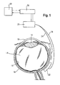
- FIG. 1 schematically shows an eye with a cornea 10, a lens 12, a vitreous body 14, a retina 16 and a dermis (sclera) 18.
- a band 20 and a cushion 22 lie directly on the outside of the dermis (sclera) 18.
- the band 20 and the pad 22 are shaped such that electromagnetic radiation in the direction of the dermis 18th can be blasted.
- the band 20 and the pad 22 may be mirrored on the side facing away from the sclera side.
- Fiber light guides 24 are connected to the belt 20 and the pad 22. It is also possible that in each case a plurality of optical fibers are connected to the band 20 and the pad 22.
- the optical fibers 24 are fed from a radiation source 26, for example a laser or LEDs, operated in either cw-mode or pulsed.
- a power supply 28 the radiation source 26 is driven, that is, the amount of radiation emitted via the optical fibers 24 can be selectively adjusted as needed.
- a control and regulation unit 30 is provided, which can be computer-controlled, for example.
- the diffuser is located inside the band 20 and pad 22 in the beam path of the radiation emitted by the optical fibers 24 radiation, a so-called "diffuser" (not shown).
- the function of the diffuser is to distribute the radiation emitted by the optical fibers 24 as uniformly as possible over the sclera, so that peaks of intensity are avoided.
- the diffuser may be formed as a frosted glass-like material.
- Another variant of the embodiment of the band 20 and the pad 22 provides that at one end of the band or the pad, the light is coupled and this then on its path parallel to the sclera through staggered reflection surfaces successively from the tape or cushion to one side exits to irradiate the sclera with homogeneous fluence (energy per unit area).
- the embodiment of Figure 1 may also be equipped with an endoscope (not shown) coupled to a surgical microscope (not shown).
- This may be provided with a filter which allows the surgeon, without being affected by the electromagnetic radiation conducted by the radiation source 26 and via the conductor fiber 24, on the one hand, the eye parts of interest and on the other hand, the diffusers can be correctly positioned under view.
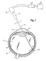
- FIG. 2 shows a modification of the treatment of the dermis 18 with electromagnetic radiation.
- electromagnetic radiation is applied to the dermis 18 via the interior of the eye through the cornea 10, the lens 12, the vitreous body 14 and the retina 16.
- Bundled radiation 34 emerges from a radiation focusing device 32, which is connected to a radiation source 26.
- the focused radiation 34 impinges on the dermis 18 at a point 38, taking into account effects that may occur within the eye and may cause a change in the direction of radiation.
- the focused radiation 34 is guided over the dermis 18 in such a way that substantially the same or a desired, spatially varying amount of radiation strikes the dermis per unit area.
- This "scanning" of the dermis 18 with radiation 34 requires movement of the radiation relative to the dermis. This can be done, for example, with a mirror (not shown) in a manner known per se. This movement of the radiation is indicated in Figure 2 with arrows.
- the radiation source 26, which feeds the radiation-focusing device 32, is driven by means of a power supply 28.
- the amount of radiation emitted by the radiation source 26 can be selectively adjusted as needed.
- a control and regulation unit 30 is provided, which can be computer-controlled, for example.
- a plurality of radiation sources 26 and / or radiation focusing devices 32 may be used to effect irradiation of the dermis 18 at multiple locations simultaneously. This would have the advantage, for example, that a treatment shortened or that the irradiation of the dermis could be carried out symmetrically.
- a radiation sensor (not shown) may be provided which detects part of the radiation directed towards the dermis.
- the measuring signal of the sensor is transmitted via a line in the control and regulation unit for processing, so that the control unit can drive according to the power supply unit for the radiation source or the radiation sources. It is preferably provided that each individual radiation source is selectively controllable, so that different radiation intensities can be provided for the individual radiation sources.
- FIG. 3 shows a further device for irradiation of the dermis 18.
- a device 36 which serves to bring about a targeted change in the radiation direction of the radiation 34.
- the device 36 which can be positioned directly on or near the cornea, it is possible to adjust the angle of incidence of the radiation directed onto the sclera so that radiation can be brought up to very close to the limbus.
- a photomediator can be applied and applied to the dermis 18 in a homogeneous or targeted manner before the treatment.
- the irradiation is carried out with infrared wavelengths or wavelengths in the visible optical range. Bengal pink or other substances which absorb in the optical wavelength range or in the near infrared are used as the photoinitiator.
- the photomediator releases radicals, which in turn generate new molecular bonds and thus strengthen the tissue ("crosslinking", "x-linking").
- the radiation source 26 is designed accordingly. It is also possible to perform a solidification of the dermis without photosensitizer only by the radiation itself. However, care must be taken here that the retina 16 is not damaged by entertaining radiation.
- the solidification of the dermis with devices according to FIGS. 1, 2 and 3 can be improved by the use of special measurements on the eye.
- the process parameters (amount of radiation, photoinitiator) with regard to the solidification of the dermis 18 can then be set as described above.
- microscopy for the evaluation of tissue effects which may occur, in order to avoid unwanted disturbances. It may also be provided during the use of the device to determine the intraocular pressure, in order to derive therefrom optionally control variables for the solidification of the dermis 18. The same applies to the use of known methods for optical spectroscopy for tissue characterization or else methods which enable tissue characterization by means of acousto-optic spectroscopy.
Landscapes
- Health & Medical Sciences (AREA)
- Ophthalmology & Optometry (AREA)
- Biomedical Technology (AREA)
- Life Sciences & Earth Sciences (AREA)
- Nuclear Medicine, Radiotherapy & Molecular Imaging (AREA)
- Electromagnetism (AREA)
- Surgery (AREA)
- Engineering & Computer Science (AREA)
- Physics & Mathematics (AREA)
- Heart & Thoracic Surgery (AREA)
- Vascular Medicine (AREA)
- Optics & Photonics (AREA)
- Animal Behavior & Ethology (AREA)
- General Health & Medical Sciences (AREA)
- Public Health (AREA)
- Veterinary Medicine (AREA)
- Laser Surgery Devices (AREA)
- Radiation-Therapy Devices (AREA)
- Eye Examination Apparatus (AREA)
Abstract
Die Verfestigung der Lederhaut erfolgt mit einer Vorrichtung mit zumindest einer Strahlungsquelle zum Bestrahlen der Lederhaut.
Description
- Die Erfindung betrifft eine Vorrichtung zur Vorbeugung einer Fehlsichtigkeit oder Lederhauterkrankung eines Auges.
- Bei der sogenannten Myopie oder Kurzsichtigkeit können weit entfernte Objekte schlechter gesehen werden als nahegelegene. Die Myopie bezeichnet eine Form der Fehlsichtigkeit, bei der der Fokus vor der Netzhaut liegt. Dabei werden zwei prinzipielle Formen der Kurzsichtigkeit unterschieden, zum einen die "Brechungsmyopie" bei normaler Augenachsenlänge, aber zu starker Brechkraft, und die sogenannte "Achsenmyopie" bei normaler Brechkraft, aber zu langer Augenachse. Für die erste Form, die "Brechungsmyopie", kennt der Stand der Technik vielfältige ophthalmologische Vorrichtungen, die der Korrektur dieses Sehfehlers dienen.
- Die zweite Form - die "Achsenmyopie" - beschreibt eine häufig auftretende Erkrankung des Auges, bei der das Auge durch (passives) Sklerawachstum länger wird. Dies erfolgt insbesondere in den ersten drei Lebensjahrzehnten. Hierbei kommt es zu einer allmählichen und übermäßigen Verlängerung des Augapfels. Die Ursachen hierfür sind noch nicht gefunden. Es wird angenommen, dass die genetische Veranlagung eine wichtige Rolle spielt.
- Derzeit sind drei Formen der "Achsenmyopie" bekannt: die Schulmyopie, die gutartige progressive Myopie und die bösartige progressive Myopie.
- Bei der Schulmyopie beginnt der Augapfel sich kurz vor der Pubertät (im Alter zwischen 10 und 12 Jahren) zu strecken und verstärkt die Kurzsichtigkeit kontinuierlich, bis das Körperwachstum mit etwa 20-25 Jahren abgeschlossen ist. Dabei können die Augen z.B. eine Brechkraft von ungefähr minus 6 Dioptrien erreichen.
- Bei der gutartigen progressiven Myopie stabilisiert sich die Brechkraft erst mit 30 Jahren. Dann kann die Kurzsichtigkeit bei ungefähr 12 Dioptrien liegen.
- Schließlich schreitet bei der bösartigen progressiven Myopie die unregelmäßige Dehnung des Augapfels auch bis ins höhere Alter weiter fort. Dann beginnt der Glaskörper zunehmend an der Netzhaut zu zerren, weil diese nicht mit der Lederhaut (Sklera) mitwächst. Hierdurch steigt das Risiko einer Netzhautablösung.
- Derzeit kennt die Ophthalmologie kein Mittel, mit dem sich das passive Sklearwachstum aufhalten ließe.
- Mit der vorliegenden Erfindung sollen eine Vorrichtung und ein Verfahren bereitgestellt werden, mit denen die vorstehend erläuterte Fehlsichtigkeit infolge einer Lederhauterkrankung oder Lederhautveränderung eines Auges behandelt werden kann.
- Die Vorrichtung ist gekennzeichnet durch eine Einrichtung zum Verfestigen der sich im hinteren Augenabschnitt befindenden Lederhaut.
- Die Verfestigung der Lederhaut erfolgt mit einer erfindungsgemäßen Vorrichtung mit zumindest einer Strahlungsquelle zum Bestrahlen der Lederhaut, wobei die zu verfestigende Lederhaut bevorzugt homogen bestrahlt wird. Eine homogene Bestrahlung mit elektromagnetischen Strahlung liegt dann vor, wenn pro Flächeneinheit im wesentlichen die gleiche Strahlungsmenge auf die Lederhaut trifft. Eine solche homogene Bestrahlung kann mit einer punktförmigen Strahlungsquelle, deren gebündelte Strahlung über die sphärisch gekrümmte Lederhaut geführt wird, erreicht werden. Gemäß einer bevorzugten Ausführungsform kann eine homogene Bestrahlung der Lederhaut auch mit einer Einrichtung erreicht werden, die die Strahlung homogen verteilt. Hierzu sieht die Erfindung bevorzugt besondere Maßnahmen zur Homogenisierung der Strahlungsverteilung vor.
- In Abwandlung der vorstehend beschriebenen Ausführungsform der Erfindung ist es auch möglich, Steuereinrichtungen für die Strahlungsverteilung über die Lederhaut so vorzusehen, dass die pro Flächeneinheit auf die Lederhaut auftreffende Strahlungsmenge in Abhängigkeit vom Ort auf der Lederhaut wahlweise einstellbar ist. Bevorzugt erfolgt die Verfestigung von circa 5 mm hinter dem Limbus bis zum hinteren Pol.
- Ferner sieht eine besondere Ausgestaltung der Erfindung vor, dass eine Einrichtung vorgesehen ist zur Bestimmung von Eigenschaften der Lederhaut und/oder anderer Komponenten des Auges. Gegebenenfalls können diese Messungen an unterschiedlichen Stellen der Lederhaut zu unterschiedlichen Ergebnissen führen, was wiederum für die oben erwähnte Steuerung der Intensitätsverteilung der elektromagnetischen Strahlung in Abhängigkeit vom Ort des Auges bei besonderen Ausführungsformen der Erfindung von Bedeutung sein kann.
- Die erfindungsgemäße Einrichtung zum Verfestigen der Lederhaut mittels elektromagnetischer Strahlung kann so gestaltet sein, dass sie einen gewählten Abstand von der Lederhaut besitzt oder auf dieser aufliegt, d.h. gemäß einer bevorzugten Ausgestaltung der Erfindung kann die Einrichtung bei bestimmungsgemäßem Gebrauch einen vorgegebenen Abstand von der Kornea besitzen oder mit der Kornea in Kontakt gebracht werden. Des weiteren lehrt die Erfindung auch unterschiedliche Strahlungsquellen für die elektromagnetische Strahlung und unterschiedliche Techniken, diese Strahlung zum Einsatzort zu führen. Einzelheiten hierzu finden sich in den abhängigen Patentansprüchen und in der nachfolgenden Beschreibung von Ausführungsbeispielen.
- Gemäß einer Variante der Erfindung ist es vorgesehen, die Einrichtung, mit der die elektromagnetische Strahlung auf die Lederhaut gestrahlt wird, mit einem Endoskop auszustatten, das mit einem Operationsmikroskop gekoppelt ist und zwar bevorzugt derart, dass der Operateur während des Aufbringens der elektromagnetischen Strahlung das Auge und insbesondere die Lederhaut oder Teile davon beobachten kann.
- Die Erfindung lehrt auch ein Verfahren zum Vorbeugen einer Fehlsichtigkeit eines Auges infolge einer Lederhauterkrankung, bei dem mit elektromagnetischer Strahlung eine Verfestigung der Lederhaut durchgeführt wird. Bei diesem Verfahren wird bevorzugt ein Photomediator eingesetzt, der in der Haut ein sogenanntes "Cross-Linking" bewirkt. Bei dem Verfahren wird die Strahlung bevorzugt homogen auf die Sklera aufgebracht oder aber gemäß einem besonderen Steuerprogramm ungleichmäßig wenn bestimmte Bereiche der Sklera anders bestrahlt werden sollen als andere Bereiche derselben, zum Beispiel aufgrund unterschiedlicher Stärken der Sklera oder aufgrund unterschiedlicher Zielvorgaben für die Verfestigung (das Cross-Linking) in Abhängigkeit vom Ort der Sklera.
- Weitere bevorzugte Ausgestaltungen der Erfindung ergeben sich aus den abhängigen Patentansprüchen und der nachfolgenden Beschreibung von Ausführungsbeispielen anhand der Zeichnung. Es zeigt:
- Figur 1
- eine Vorrichtung zur Vorbeugung einer Fehlsichtigkeit eines Auges;
- Figur 2
- eine abgewandelte Ausführungsform einer Vorrichtung zur Vorbeugung einer Fehlsichtigkeit des Auges;
- Figur 3
- eine weitere Ausführungsform einer Vorrichtung zur Vorbeugung einer Fehlsichtigkeit des Auges;
- In den Figuren sind einander entsprechende oder funktionsähnliche Bauteile mit gleichen Bezugszeichen versehen.
- Figur 1 zeigt schematisch ein Auge mit einer Hornhaut 10, einer Linse 12, einem Glaskörper 14, einer Netzhaut 16 und einer Lederhaut (Sklera) 18.
- Beim Ausführungsbeispiel nach Figur 1 liegen ein Band 20 und ein Kissen 22 direkt von Außen auf der Lederhaut (Sklera) 18 auf. Das Band 20 und das Kissen 22 sind derart geformt, dass elektromagnetische Strahlung in Richtung auf die Lederhaut 18 gestrahlt werden kann. Dazu können das Band 20 und das Kissen 22 auf der von der Sklera abgekehrten Seite verspiegelt sein.
- Faserlichtleiter 24 sind mit dem Band 20 und dem Kissen 22 verbunden. Es ist auch möglich, dass jeweils mehrere Lichtleiterfasern mit dem Band 20 und dem Kissen 22 verbunden sind. Im dargestellten Ausführungsbeispiel werden die Lichtleiterfasern 24 aus einer Strahlungsquelle 26, zum Beispiel einem Laser oder LEDs, die entweder in cw-mode oder gepulst betrieben werden, gespeist. Mittels einer Stormversorgung 28 wird die Strahlungsquelle 26 angesteuert, das heißt, die über die Lichtleiterfasern 24 abgegebene Strahlungsmenge kann selektiv, je nach Bedarf, eingestellt werden. Für die Steuerung der von der Strahlungsquelle 26 abgegebenen Strahlungsmengen ist eine Steuer- und Regeleinheit 30 vorgesehen, die zum Beispiel rechnergesteuert sein kann.
- Im Inneren des Bandes 20 und Kissens 22 befindet sich im Strahlengang der von den Lichtleiterfasern 24 abgegebenen Strahlung, ein sogenannter "Diffusor" (nicht gezeigt). Die Funktion des Diffusors ist es, die von den Lichtleiterfasern 24 abgegebene Strahlung möglichst gleichmäßig über die Sklera zu verteilen, sodass Intensitätsspitzen vermieden werden. Zum Beispiel kann der Diffusor als milchglasartig streuendes Material ausgebildet sein. Eine andere Variante der Ausgestaltung des Bandes 20 und des Kissens 22 sieht vor, dass an einem Stirnende des Bandes bzw. des Kissens das Licht eingekoppelt wird und dieses dann auf seinem Laufweg parallel zur Sklera durch gestaffelte Reflexionsflächen sukzessive aus dem Band oder Kissen nach einer Seite austritt, um die Sklera mit homogener fluence (Energie pro Flächeneinheit) zu bestrahlen.
- Das Ausführungsbeispiel nach Figur 1 kann auch mit einem Endoskop (nicht gezeigt) ausgestattet werden, das mit einem Operationsmikroskop (nicht gezeigt) gekoppelt ist. Dieses kann mit einem Filter versehen sein, das ermöglicht, dass der Operateur ohne Beeinträchtigung durch die von der Strahlungsquelle 26 und über die Leiterfaser 24 geleitete elektromagnetische Strahlung, einerseits die interessierenden Augenteile beobachten kann und andererseits die Diffusoren unter Sicht richtig positioniert werden können.
- Figur 2 zeigt eine Abwandlung der Behandlung der Lederhaut 18 mit elektromagnetischer Strahlung. Bei dem Ausführungsbeispiel nach Figur 2 wird elektromagnetische Strahlung über das Innere des Auges durch die Hornhaut 10, die Linse 12, den Glaskörper 14 und die Netzhaut 16 auf die Lederhaut 18 appliziert. Dabei tritt gebündelte Strahlung 34 aus einer Strahlungsfokussierungseinrichtung 32 aus, die mit einer Strahlungsquelle 26 verbunden ist. Die gebündelte Strahlung 34 trifft unter Berücksichtigung von Effekten, die innerhalb des Auges auftreten können und eine Veränderung der Strahlungsrichtung bewirken können, auf die Lederhaut 18 in einem Punkt 38 auf. Um eine homogene Bestrahlung der Lederhaut 18 zu bewirken, wird die gebündelte Strahlung 34 derart über die Lederhaut 18 geführt, dass pro Flächeneinheit im wesentlichen die gleiche oder eine gewünschte, örtlich variierende Strahlungsmenge auf die Lederhaut trifft. Dieses "Abscannen" der Lederhaut 18 mit Strahlung 34 erfordert eine Bewegung der Strahlung relativ zur Lederhaut. Dies kann zum Beispiel mit einem Spiegel (nicht gezeigt) in an sich bekannter Weise durchgeführt werden. Diese Bewegung der Strahlung ist in Figur 2 mit Pfeilen angedeutet.
- Die Strahlungsquelle 26, die die Strahlungsfokussierungseinrichtung 32 speist, wird mittels einer Stromversorgung 28 angesteuert. Die von der Strahlungsquelle 26 abgegebene Strahlungsmenge kann selektiv, je nach Bedarf eingestellt werden. Für die Steuerung der von der Strahlungsquelle 26 abgegebenen Strahlungsmenge ist eine Steuer- und Regeleinheit 30 vorgesehen, die zum Beispiel rechnergesteuert sein kann.
- Während einer Bestrahlung können mehrere Strahlungsquellen 26 und oder Strahlungsfokussierungseinrichtungen 32 eingesetzt werden, um eine Bestrahlung der Lederhaut 18 an mehreren Stellen gleichzeitig zu bewirken. Dies hätte zum Beispiel den Vorteil, dass eine Behandlung verkürzt, oder dass die Bestrahlung der Lederhaut symmetrisch ausgeführt werden könnte.
- Zusätzlich kann ein Strahlungssensor (nicht gezeigt) vorgesehen sein, der einen Teil der in Richtung auf die Lederhaut gerichteten Strahlung erfasst. Das Messsignal des Sensors wird über eine Leitung in die Steuer- und Regeleinheit zur Verarbeitung übertragen, damit die Steuer- und Regeleinheit entsprechend die Stromversorgungseinheit für die Strahlungsquelle bzw. die Strahlungsquellen ansteuern kann. Dabei ist bevorzugt vorgesehen, dass jede einzelne Strahlungsquelle selektiv ansteuerbar ist, so dass für die einzelnen Strahlungsquellen unterschiedliche Strahlungsintensitäten vorgesehen werden können.
- Zusätzlich kann ein als solches bekannter sogenannter "Justierstrahl" für die Positionierung des Auges eingesetzt werden. Ein solcher Strahl wird in der Literatur auch bisweilen als "Fixierlichtstrahl" bezeichnet. Damit lässt sich die Positionierung des Auges in Bezug auf die beschriebenen Vorrichtungen und den Laserstrahl 34 verbessern. Es ist auch möglich, die hier beschriebenen Vorrichtungen mit einem sogenannten "eye-tracker" zu kombinieren. Solche "eye-tracker" sind Augenverfolgungssysteme, die mögliche Bewegungen des Auges optisch verfolgen und für die Chirurgie eingesetzten Instrumente, zum Beispiel Laserstrahlen, entsprechend der Augenbewegung nachführen.
- Figur 3 zeigt eine weitere Vorrichtung zur Bestrahlung der Lederhaut 18. Bei diesem Ausführungsbeispiel befindet sich zwischen der Strahlungsfokussierungseinrichtung 32 und der Hornhaut 10 eine Einrichtung 36, die dazu dient, eine gezielte Änderung der Strahlungsrichtung der Strahlung 34 herbeizuführen. Mit der Einrichtung 36, die direkt auf oder nahe der Kornea positionierbar ist, ist es möglich, den Einstrahlwinkel der auf die Sklera gerichteten Strahlung so einzustellen, dass Strahlung bis sehr nahe an den Limbus herangeführt werden kann.
- Es ist, gemäß einer anderen Variante der Erfindung auch möglich, die Positionierung der beschriebenen Vorrichtungen und Einrichtungen am Auge, mit einem Brillengestell zu fördern.
- Mit den anhand der Figuren 1, 2 und 3 erläuterten Ausführungsbeispielen der Erfindung ist es möglich, die Lederhaut 18 zu festigen. Hierfür kann vor der Behandlung ein Photomediator auf die Lederhaut 18 homogen oder gezielt aufgebracht und eingebracht werden. Die Bestrahlung wird mit Infrarot-Wellenlängen oder Wellenlängen im sichtbaren optischen Bereich durchgeführt. Als Photomediator dienen insbesondere Bengalrosa oder andere Substanzen, die im optischen Wellenlängenbereich oder im nahen Infrarot absorbieren. Dabei setzt der Photomediator Radikale frei, die ihrerseits neue molekulare Bindungen erzeugen und somit das Gewebe festigen ("crosslinking", "x-linking"). Die Strahlungsquelle 26 ist hierfür entsprechend ausgelegt. Es ist auch möglich, eine Verfestigung der Lederhaut ohne Photosensibilisator nur durch die Strahlung selbst durchzuführen. Jedoch muss hierbei darauf geachtet werden, dass die Netzhaut 16 nicht durch kurzweilige Strahlung geschädigt wird.
- Die Verfestigung der Lederhaut mit Vorrichtungen gemäß den Figuren 1, 2 und 3 kann durch den Einsatz von besonderen Messungen am Auge verbessert werden.
- So ist es zum Beispiel mit Mitteln, die der Strand der Technik bereithält, möglich, die Lederhautdicke und Lederhautfestigkeit optisch oder akustisch zu bestimmen. In Abhängigkeit von der so ermittelten Lederhautdicke oder anderen Parametern können dann die Prozessparameter (Strahlungsmenge, Photomediator) hinsichtlich der Verfestigung der Lederhaut 18, wie oben beschrieben eingestellt werden.
- Es ist auch möglich, zusammen mit den gezeigten Vorrichtungen die Mikroskopie zur Beurteilung von eventuell auftretenden Gewebeeffekten einzusetzen, um unerwünschte Störungen zu vermeiden. Auch kann während des Einsatzes der Vorrichtung vorgesehen sein, den Augeninnendruck zu bestimmen, um daraus gegebenenfalls Steuergrößen für die Verfestigung der Lederhaut 18 abzuleiten. Entsprechendes gilt für den Einsatz von bekannten Verfahren für die optische Spektroskopie zur Gewebecharakterisierung oder auch Verfahren, die mittels akustooptischer Spektroskopie eine Gewebecharakterisierung ermöglichen.
Claims (15)
- Vorrichtung zur Vorbeugung einer Fehlsichtigkeit infolge einer Lederhauterkrankung oder Lederhautveränderung eines Auges, gekennzeichnet durch eine Einrichtung (20, 22; 32) zum Verfestigen der Lederhaut (18).
- Vorrichtung nach Anspruch 1 dadurch gekennzeichnet, dass die Einrichtung (20, 22; 32) Mittel aufweist zum Bestrahlen der Lederhaut (18).
- Vorrichtung nach Anspruch 2, dadurch gekennzeichnet, dass als Strahlungsquelle ein oder mehrere LASER oder LEDs vorgesehen sind.
- Vorrichtung nach Anspruch 1 bis 3, wobei die Einrichtung (20, 22) die Strahlung homogen abgibt.
- Vorrichtung nach Anspruch 3 und 4, dadurch gekennzeichnet, dass die Einrichtung mehrere Lichtleiterfasern (24) aufweist, die so angeordnet sind, dass ihre Strahlungskegel durch Überlappung eine homogene Beleuchtung der Lederhaut (18) ermöglichen.
- Vorrichtung nach Anspruch 2 oder 3, wobei die Einrichtung (32) die Strahlung punktuell/gebündelt auf die Lederhaut (18) abgibt.
- Vorrichtung nach Anspruch 1, 2, 3 und 6, dadurch gekennzeichnet, dass mit Hilfe der Einrichtung (32) die Lederhaut (18) durch Führung von Strahlung (34) homogen bestrahlt wird.
- Vorrichtung nach einem der Ansprüche 1 bis 5, dadurch gekennzeichnet, dass die Einrichtung (20, 22) so gestaltet ist, dass sie bei bestimmungsmäßigem Gebrauch in Kontakt mit der Lederhaut (18) gebracht werden kann.
- Vorrichtung nach einem der Ansprüche 1 bis 3, 6 und 7, dadurch gekennzeichnet, dass die Einrichtung (36) bei bestimmungsgemäßem Gebrauch einen vorgegebenen Abstand von der Kornea (10) besitzt oder mit der Kornea (10) in Kontakt gebracht werden kann.
- Vorrichtung nach einem der Ansprüche 2 bis 5 und 9 mit einem Band (20) und/oder einem Kissen (22) zur Strahlungsverteilung.
- Vorrichtung nach einem der Ansprüche 1 bis 3, 6, 7 und 10 mit einer Strahlungsfokussierungseinrichtung (32) zur gebündelten Strahlungsabgabe.
- Vorrichtung nach einem der vorhergehenden Ansprüche mit einer Einrichtung (36) zur Änderung des Strahlungsweges.
- Vorrichtung nach einem der Ansprüche 2 bis 12, gekennzeichnet durch eine Steuer- oder Regeleinrichtung (30), mit der die Strahlung steuer- oder regelbar ist.
- Vorrichtung nach einem der Ansprüche 2 bis 13, mit Mitteln zum Bestimmen von Eigenschaften der Lederhaut.
- Vorrichtung nach einem der vorhergehenden Ansprüche mit einem Photomediator.
Priority Applications (3)
| Application Number | Priority Date | Filing Date | Title |
|---|---|---|---|
| EP06009539.5A EP1854438B1 (de) | 2006-05-09 | 2006-05-09 | Ophthalmologische Vorrichtung zur Vorbeugung einer Myopie |
| PCT/EP2007/004115 WO2007128581A2 (de) | 2006-05-09 | 2007-05-09 | Ophthalmologische vorrichtung zur vorbeugung einer myopie |
| EP07725037.1A EP2015720B1 (de) | 2006-05-09 | 2007-05-09 | Ophthalmologische vorrichtung zur vorbeugung einer myopie |
Applications Claiming Priority (1)
| Application Number | Priority Date | Filing Date | Title |
|---|---|---|---|
| EP06009539.5A EP1854438B1 (de) | 2006-05-09 | 2006-05-09 | Ophthalmologische Vorrichtung zur Vorbeugung einer Myopie |
Publications (2)
| Publication Number | Publication Date |
|---|---|
| EP1854438A1 true EP1854438A1 (de) | 2007-11-14 |
| EP1854438B1 EP1854438B1 (de) | 2018-07-04 |
Family
ID=37110205
Family Applications (2)
| Application Number | Title | Priority Date | Filing Date |
|---|---|---|---|
| EP06009539.5A Not-in-force EP1854438B1 (de) | 2006-05-09 | 2006-05-09 | Ophthalmologische Vorrichtung zur Vorbeugung einer Myopie |
| EP07725037.1A Not-in-force EP2015720B1 (de) | 2006-05-09 | 2007-05-09 | Ophthalmologische vorrichtung zur vorbeugung einer myopie |
Family Applications After (1)
| Application Number | Title | Priority Date | Filing Date |
|---|---|---|---|
| EP07725037.1A Not-in-force EP2015720B1 (de) | 2006-05-09 | 2007-05-09 | Ophthalmologische vorrichtung zur vorbeugung einer myopie |
Country Status (2)
| Country | Link |
|---|---|
| EP (2) | EP1854438B1 (de) |
| WO (1) | WO2007128581A2 (de) |
Cited By (3)
| Publication number | Priority date | Publication date | Assignee | Title |
|---|---|---|---|---|
| EP2380535A1 (de) | 2010-04-21 | 2011-10-26 | Iroc AG | Vorrichtung für die Vernetzung von okulärem Gewebe mit elektromagnetischer Strahlung |
| EP2407132A1 (de) | 2010-06-24 | 2012-01-18 | IROC Services AG | Vorrichtung zum Präparieren eines Auges für das Einbringen von Photosensibilisator |
| EP3053553A1 (de) | 2015-02-09 | 2016-08-10 | IROC Services AG | Vorrichtung zur Prävention von Achsenmyopie des Auges |
Families Citing this family (9)
| Publication number | Priority date | Publication date | Assignee | Title |
|---|---|---|---|---|
| DE102008046834A1 (de) | 2008-09-11 | 2010-03-18 | Iroc Ag | Steuerprogramm zum Steuern elektromagnetischer Strahlung für eine Quervernetzung von Augengewebe |
| JP6377906B2 (ja) | 2010-03-19 | 2018-08-22 | アヴェドロ・インコーポレーテッドAvedro,Inc. | 眼治療を適用およびモニターするためのシステム |
| WO2012167260A2 (en) | 2011-06-02 | 2012-12-06 | Avedro, Inc. | Systems and methods for monitoring time based photo active agent delivery or photo active marker presence |
| KR102545628B1 (ko) | 2014-10-27 | 2023-06-20 | 아베드로 인코퍼레이티드 | 눈의 교차-결합 처리를 위한 시스템 및 방법 |
| WO2016077747A1 (en) | 2014-11-13 | 2016-05-19 | Avedro, Inc. | Multipass virtually imaged phased array etalon |
| EP3285704B1 (de) | 2015-04-24 | 2020-11-18 | Avedro Inc. | Systeme zur lichtaktivierung eines an einem auge applizierten lichtsensibilisators |
| US10028657B2 (en) | 2015-05-22 | 2018-07-24 | Avedro, Inc. | Systems and methods for monitoring cross-linking activity for corneal treatments |
| KR102706856B1 (ko) | 2015-07-21 | 2024-09-19 | 아베드로 인코퍼레이티드 | 광증감제로 눈을 치료하기 위한 시스템 및 방법 |
| WO2024044806A1 (en) * | 2022-09-02 | 2024-03-07 | The University Of Newcastle | Treating myopia |
Citations (6)
| Publication number | Priority date | Publication date | Assignee | Title |
|---|---|---|---|---|
| WO1990011054A1 (en) * | 1989-03-17 | 1990-10-04 | Candela Laser Corporation | Non-invasive sclerostomy laser apparatus and method |
| US5445608A (en) * | 1993-08-16 | 1995-08-29 | James C. Chen | Method and apparatus for providing light-activated therapy |
| WO1999044491A1 (en) * | 1998-03-06 | 1999-09-10 | Odyssey Optical Systems, Llc | System for treating the fundus of an eye |
| WO2001087181A2 (en) * | 2000-05-12 | 2001-11-22 | Ceramoptec Industries, Inc. | Accurate optical treatment of an eye's fundus |
| US20030009205A1 (en) * | 1997-08-25 | 2003-01-09 | Biel Merrill A. | Treatment device for topical photodynamic therapy and method of using same |
| WO2005110397A1 (en) * | 2004-05-07 | 2005-11-24 | The Regents Of The University Of California | Treatment of myopia |
Family Cites Families (2)
| Publication number | Priority date | Publication date | Assignee | Title |
|---|---|---|---|---|
| US6443976B1 (en) * | 1999-11-30 | 2002-09-03 | Akorn, Inc. | Methods for treating conditions and illnesses associated with abnormal vasculature |
| US20070123844A1 (en) * | 2005-10-19 | 2007-05-31 | Shelly Henry | Method for treating ocular disorders |
-
2006
- 2006-05-09 EP EP06009539.5A patent/EP1854438B1/de not_active Not-in-force
-
2007
- 2007-05-09 EP EP07725037.1A patent/EP2015720B1/de not_active Not-in-force
- 2007-05-09 WO PCT/EP2007/004115 patent/WO2007128581A2/de not_active Ceased
Patent Citations (6)
| Publication number | Priority date | Publication date | Assignee | Title |
|---|---|---|---|---|
| WO1990011054A1 (en) * | 1989-03-17 | 1990-10-04 | Candela Laser Corporation | Non-invasive sclerostomy laser apparatus and method |
| US5445608A (en) * | 1993-08-16 | 1995-08-29 | James C. Chen | Method and apparatus for providing light-activated therapy |
| US20030009205A1 (en) * | 1997-08-25 | 2003-01-09 | Biel Merrill A. | Treatment device for topical photodynamic therapy and method of using same |
| WO1999044491A1 (en) * | 1998-03-06 | 1999-09-10 | Odyssey Optical Systems, Llc | System for treating the fundus of an eye |
| WO2001087181A2 (en) * | 2000-05-12 | 2001-11-22 | Ceramoptec Industries, Inc. | Accurate optical treatment of an eye's fundus |
| WO2005110397A1 (en) * | 2004-05-07 | 2005-11-24 | The Regents Of The University Of California | Treatment of myopia |
Non-Patent Citations (1)
| Title |
|---|
| DATABASE WPI Week 199345, Derwent World Patents Index; AN 1993-358292, XP002404536 * |
Cited By (7)
| Publication number | Priority date | Publication date | Assignee | Title |
|---|---|---|---|---|
| EP2380535A1 (de) | 2010-04-21 | 2011-10-26 | Iroc AG | Vorrichtung für die Vernetzung von okulärem Gewebe mit elektromagnetischer Strahlung |
| US8936591B2 (en) | 2010-04-21 | 2015-01-20 | Iroc Innocross Ag | Apparatus for the cross-linking of ocular tissue with electromagnetic radiation |
| EP2907489A1 (de) | 2010-04-21 | 2015-08-19 | IROC Innocross AG | Vorrichtung für die vernetzung von okulärem gewebe mit elektromagnetischer strahlung |
| EP2907490A1 (de) | 2010-04-21 | 2015-08-19 | IROC Innocross AG | Vorrichtung für die vernetzung von okulärem gewebe mit elektromagnetischer strahlung |
| EP2407132A1 (de) | 2010-06-24 | 2012-01-18 | IROC Services AG | Vorrichtung zum Präparieren eines Auges für das Einbringen von Photosensibilisator |
| EP2407132B1 (de) * | 2010-06-24 | 2014-04-30 | WaveLight GmbH | Vorrichtung zum Präparieren eines Auges für das Einbringen von Photosensibilisator |
| EP3053553A1 (de) | 2015-02-09 | 2016-08-10 | IROC Services AG | Vorrichtung zur Prävention von Achsenmyopie des Auges |
Also Published As
| Publication number | Publication date |
|---|---|
| EP2015720A2 (de) | 2009-01-21 |
| EP1854438B1 (de) | 2018-07-04 |
| EP2015720B1 (de) | 2018-07-11 |
| WO2007128581A2 (de) | 2007-11-15 |
| WO2007128581A3 (de) | 2008-01-03 |
Similar Documents
| Publication | Publication Date | Title |
|---|---|---|
| EP2015720B1 (de) | Ophthalmologische vorrichtung zur vorbeugung einer myopie | |
| EP1561440B1 (de) | Ophtalmologische Vorrichtung | |
| DE3786308T2 (de) | In-vitro Verfahren und Gerät zur Modifikation der Brechungseigenshaften der Hornhaut. | |
| EP2907489B1 (de) | Vorrichtung für die vernetzung von okulärem gewebe mit elektromagnetischer strahlung | |
| DE69122349T2 (de) | Lasergerät zu thermischer Hornhautplastik | |
| DE69033376T2 (de) | Vorrichtung zur Behandlung von Kollagen | |
| EP2133048B1 (de) | Apparat zur Ankopplung eines Elementes an das Auge | |
| EP2231084B1 (de) | Laserkorrektur von sehfehlern an der natürlichen augenlinse | |
| DE19954710C1 (de) | Vorrichtung zur Behandlung von wachsenden, erweiterten oder mißgebildeten Blutgefäßen | |
| DE69131602T2 (de) | Vorrichtung für die hornhautumformung zum korrigieren von brechungsfehlern des auges | |
| DE102019007147A1 (de) | Anordnung zur Laser-Vitreolyse | |
| DE112008002511T5 (de) | Verfahren und Vorrichtungen für integrierte Kataraktchirurgie | |
| EP1514633A2 (de) | Vorrichtung zum Formgebung von Objekten | |
| EP2408410B1 (de) | Lasereinrichtung für die ophthalmologie | |
| EP1758498B1 (de) | Vorrichtung und verfahren zum erfassen der räumlichen lage der optischen achse eines auges | |
| DE60036808T2 (de) | Bewegungsdetektor für ophthalmologische laserablationssysteme | |
| DE102006043889A1 (de) | Vorrichtung und Verfahren zum Durchführen von Messungen mit einer optischen Kohärenztomographie-Vorrichtung während eines chirurgischen Eingriffs | |
| EP3053553B1 (de) | Vorrichtung zur Prävention von Achsenmyopie des Auges | |
| DE102013004482A1 (de) | Vorrichtung und Verfahren zur Stabilisierung der Augenhornhaut | |
| DE19943735B4 (de) | Vorrichtung zur Bestrahlung des Auges | |
| WO2001037031A1 (de) | Verfahren zur oberflächenbearbeitung einer kontaktlinse zur individuellen anpassung an das system auge | |
| DE19943723A1 (de) | Verfahren und Vorrichtung zur Bestrahlung des Auges | |
| EP3318227B1 (de) | System für die fragmentierung eines augenlinsenkerns | |
| DE102017124545B3 (de) | Mikroskop | |
| EP2033605B1 (de) | Lasersystem zum Ablatieren von Hornhaut an einem Patientenauge |
Legal Events
| Date | Code | Title | Description |
|---|---|---|---|
| PUAI | Public reference made under article 153(3) epc to a published international application that has entered the european phase |
Free format text: ORIGINAL CODE: 0009012 |
|
| AK | Designated contracting states |
Kind code of ref document: A1 Designated state(s): AT BE BG CH CY CZ DE DK EE ES FI FR GB GR HU IE IS IT LI LT LU LV MC NL PL PT RO SE SI SK TR |
|
| AX | Request for extension of the european patent |
Extension state: AL BA HR MK YU |
|
| 17P | Request for examination filed |
Effective date: 20080514 |
|
| 17Q | First examination report despatched |
Effective date: 20080617 |
|
| AKX | Designation fees paid |
Designated state(s): AT BE BG CH CY CZ DE DK EE ES FI FR GB GR HU IE IS IT LI LT LU LV MC NL PL PT RO SE SI SK TR |
|
| RAP1 | Party data changed (applicant data changed or rights of an application transferred) |
Owner name: SEILER, THEO Owner name: KOLLER, TOBIAS Owner name: SEILER, STEFAN |
|
| RIN1 | Information on inventor provided before grant (corrected) |
Inventor name: SEILER, STEFAN Inventor name: KOLLER, TOBIAS Inventor name: SEILER, THEO |
|
| RAP1 | Party data changed (applicant data changed or rights of an application transferred) |
Owner name: FALCON TRADING AG Owner name: KOLLER, TOBIAS Owner name: SEILER, STEFAN |
|
| RIN1 | Information on inventor provided before grant (corrected) |
Inventor name: STEFAN SEILER Inventor name: THEO SEILER Inventor name: DR TOBIAS KOLLER |
|
| RAP1 | Party data changed (applicant data changed or rights of an application transferred) |
Owner name: KOLLER, TOBIAS Owner name: IROC INNOCROSS AG Owner name: SEILER, STEFAN |
|
| RAP1 | Party data changed (applicant data changed or rights of an application transferred) |
Owner name: IROC INNOCROSS AG Owner name: SEILER, STEFAN Owner name: KOLLER, TOBIAS |
|
| RAP1 | Party data changed (applicant data changed or rights of an application transferred) |
Owner name: IROC SERVICES AG Owner name: KOLLER, TOBIAS Owner name: SEILER, STEFAN |
|
| GRAP | Despatch of communication of intention to grant a patent |
Free format text: ORIGINAL CODE: EPIDOSNIGR1 |
|
| STAA | Information on the status of an ep patent application or granted ep patent |
Free format text: STATUS: GRANT OF PATENT IS INTENDED |
|
| INTG | Intention to grant announced |
Effective date: 20180202 |
|
| RIN1 | Information on inventor provided before grant (corrected) |
Inventor name: SEILER, STEFAN Inventor name: KOLLER, TOBIAS Inventor name: SEILER, THEO |
|
| GRAS | Grant fee paid |
Free format text: ORIGINAL CODE: EPIDOSNIGR3 |
|
| GRAA | (expected) grant |
Free format text: ORIGINAL CODE: 0009210 |
|
| STAA | Information on the status of an ep patent application or granted ep patent |
Free format text: STATUS: THE PATENT HAS BEEN GRANTED |
|
| AK | Designated contracting states |
Kind code of ref document: B1 Designated state(s): AT BE BG CH CY CZ DE DK EE ES FI FR GB GR HU IE IS IT LI LT LU LV MC NL PL PT RO SE SI SK TR |
|
| REG | Reference to a national code |
Ref country code: GB Ref legal event code: FG4D Free format text: NOT ENGLISH |
|
| RIN1 | Information on inventor provided before grant (corrected) |
Inventor name: SEILER, STEFAN Inventor name: SEILER, THEO Inventor name: KOLLER, TOBIAS |
|
| REG | Reference to a national code |
Ref country code: CH Ref legal event code: EP |
|
| REG | Reference to a national code |
Ref country code: AT Ref legal event code: REF Ref document number: 1013714 Country of ref document: AT Kind code of ref document: T Effective date: 20180715 |
|
| REG | Reference to a national code |
Ref country code: IE Ref legal event code: FG4D Free format text: LANGUAGE OF EP DOCUMENT: GERMAN |
|
| REG | Reference to a national code |
Ref country code: DE Ref legal event code: R096 Ref document number: 502006015940 Country of ref document: DE |
|
| REG | Reference to a national code |
Ref country code: NL Ref legal event code: MP Effective date: 20180704 |
|
| REG | Reference to a national code |
Ref country code: LT Ref legal event code: MG4D |
|
| PG25 | Lapsed in a contracting state [announced via postgrant information from national office to epo] |
Ref country code: NL Free format text: LAPSE BECAUSE OF FAILURE TO SUBMIT A TRANSLATION OF THE DESCRIPTION OR TO PAY THE FEE WITHIN THE PRESCRIBED TIME-LIMIT Effective date: 20180704 |
|
| PG25 | Lapsed in a contracting state [announced via postgrant information from national office to epo] |
Ref country code: PL Free format text: LAPSE BECAUSE OF FAILURE TO SUBMIT A TRANSLATION OF THE DESCRIPTION OR TO PAY THE FEE WITHIN THE PRESCRIBED TIME-LIMIT Effective date: 20180704 Ref country code: LT Free format text: LAPSE BECAUSE OF FAILURE TO SUBMIT A TRANSLATION OF THE DESCRIPTION OR TO PAY THE FEE WITHIN THE PRESCRIBED TIME-LIMIT Effective date: 20180704 Ref country code: IS Free format text: LAPSE BECAUSE OF FAILURE TO SUBMIT A TRANSLATION OF THE DESCRIPTION OR TO PAY THE FEE WITHIN THE PRESCRIBED TIME-LIMIT Effective date: 20181104 Ref country code: BG Free format text: LAPSE BECAUSE OF FAILURE TO SUBMIT A TRANSLATION OF THE DESCRIPTION OR TO PAY THE FEE WITHIN THE PRESCRIBED TIME-LIMIT Effective date: 20181004 Ref country code: CZ Free format text: LAPSE BECAUSE OF FAILURE TO SUBMIT A TRANSLATION OF THE DESCRIPTION OR TO PAY THE FEE WITHIN THE PRESCRIBED TIME-LIMIT Effective date: 20180704 Ref country code: GR Free format text: LAPSE BECAUSE OF FAILURE TO SUBMIT A TRANSLATION OF THE DESCRIPTION OR TO PAY THE FEE WITHIN THE PRESCRIBED TIME-LIMIT Effective date: 20181005 Ref country code: FI Free format text: LAPSE BECAUSE OF FAILURE TO SUBMIT A TRANSLATION OF THE DESCRIPTION OR TO PAY THE FEE WITHIN THE PRESCRIBED TIME-LIMIT Effective date: 20180704 Ref country code: SE Free format text: LAPSE BECAUSE OF FAILURE TO SUBMIT A TRANSLATION OF THE DESCRIPTION OR TO PAY THE FEE WITHIN THE PRESCRIBED TIME-LIMIT Effective date: 20180704 |
|
| PG25 | Lapsed in a contracting state [announced via postgrant information from national office to epo] |
Ref country code: LV Free format text: LAPSE BECAUSE OF FAILURE TO SUBMIT A TRANSLATION OF THE DESCRIPTION OR TO PAY THE FEE WITHIN THE PRESCRIBED TIME-LIMIT Effective date: 20180704 Ref country code: ES Free format text: LAPSE BECAUSE OF FAILURE TO SUBMIT A TRANSLATION OF THE DESCRIPTION OR TO PAY THE FEE WITHIN THE PRESCRIBED TIME-LIMIT Effective date: 20180704 |
|
| REG | Reference to a national code |
Ref country code: DE Ref legal event code: R097 Ref document number: 502006015940 Country of ref document: DE |
|
| PG25 | Lapsed in a contracting state [announced via postgrant information from national office to epo] |
Ref country code: IT Free format text: LAPSE BECAUSE OF FAILURE TO SUBMIT A TRANSLATION OF THE DESCRIPTION OR TO PAY THE FEE WITHIN THE PRESCRIBED TIME-LIMIT Effective date: 20180704 Ref country code: EE Free format text: LAPSE BECAUSE OF FAILURE TO SUBMIT A TRANSLATION OF THE DESCRIPTION OR TO PAY THE FEE WITHIN THE PRESCRIBED TIME-LIMIT Effective date: 20180704 Ref country code: RO Free format text: LAPSE BECAUSE OF FAILURE TO SUBMIT A TRANSLATION OF THE DESCRIPTION OR TO PAY THE FEE WITHIN THE PRESCRIBED TIME-LIMIT Effective date: 20180704 |
|
| PLBE | No opposition filed within time limit |
Free format text: ORIGINAL CODE: 0009261 |
|
| STAA | Information on the status of an ep patent application or granted ep patent |
Free format text: STATUS: NO OPPOSITION FILED WITHIN TIME LIMIT |
|
| PG25 | Lapsed in a contracting state [announced via postgrant information from national office to epo] |
Ref country code: DK Free format text: LAPSE BECAUSE OF FAILURE TO SUBMIT A TRANSLATION OF THE DESCRIPTION OR TO PAY THE FEE WITHIN THE PRESCRIBED TIME-LIMIT Effective date: 20180704 Ref country code: SK Free format text: LAPSE BECAUSE OF FAILURE TO SUBMIT A TRANSLATION OF THE DESCRIPTION OR TO PAY THE FEE WITHIN THE PRESCRIBED TIME-LIMIT Effective date: 20180704 |
|
| 26N | No opposition filed |
Effective date: 20190405 |
|
| PG25 | Lapsed in a contracting state [announced via postgrant information from national office to epo] |
Ref country code: SI Free format text: LAPSE BECAUSE OF FAILURE TO SUBMIT A TRANSLATION OF THE DESCRIPTION OR TO PAY THE FEE WITHIN THE PRESCRIBED TIME-LIMIT Effective date: 20180704 |
|
| REG | Reference to a national code |
Ref country code: CH Ref legal event code: PL |
|
| GBPC | Gb: european patent ceased through non-payment of renewal fee |
Effective date: 20190509 |
|
| PG25 | Lapsed in a contracting state [announced via postgrant information from national office to epo] |
Ref country code: CH Free format text: LAPSE BECAUSE OF NON-PAYMENT OF DUE FEES Effective date: 20190531 Ref country code: MC Free format text: LAPSE BECAUSE OF FAILURE TO SUBMIT A TRANSLATION OF THE DESCRIPTION OR TO PAY THE FEE WITHIN THE PRESCRIBED TIME-LIMIT Effective date: 20180704 Ref country code: LI Free format text: LAPSE BECAUSE OF NON-PAYMENT OF DUE FEES Effective date: 20190531 |
|
| REG | Reference to a national code |
Ref country code: BE Ref legal event code: MM Effective date: 20190531 |
|
| PG25 | Lapsed in a contracting state [announced via postgrant information from national office to epo] |
Ref country code: LU Free format text: LAPSE BECAUSE OF NON-PAYMENT OF DUE FEES Effective date: 20190509 |
|
| PG25 | Lapsed in a contracting state [announced via postgrant information from national office to epo] |
Ref country code: TR Free format text: LAPSE BECAUSE OF FAILURE TO SUBMIT A TRANSLATION OF THE DESCRIPTION OR TO PAY THE FEE WITHIN THE PRESCRIBED TIME-LIMIT Effective date: 20180704 |
|
| PG25 | Lapsed in a contracting state [announced via postgrant information from national office to epo] |
Ref country code: GB Free format text: LAPSE BECAUSE OF NON-PAYMENT OF DUE FEES Effective date: 20190509 Ref country code: IE Free format text: LAPSE BECAUSE OF NON-PAYMENT OF DUE FEES Effective date: 20190509 |
|
| PG25 | Lapsed in a contracting state [announced via postgrant information from national office to epo] |
Ref country code: BE Free format text: LAPSE BECAUSE OF NON-PAYMENT OF DUE FEES Effective date: 20190531 |
|
| PG25 | Lapsed in a contracting state [announced via postgrant information from national office to epo] |
Ref country code: PT Free format text: LAPSE BECAUSE OF FAILURE TO SUBMIT A TRANSLATION OF THE DESCRIPTION OR TO PAY THE FEE WITHIN THE PRESCRIBED TIME-LIMIT Effective date: 20181105 Ref country code: FR Free format text: LAPSE BECAUSE OF NON-PAYMENT OF DUE FEES Effective date: 20190531 |
|
| REG | Reference to a national code |
Ref country code: AT Ref legal event code: MM01 Ref document number: 1013714 Country of ref document: AT Kind code of ref document: T Effective date: 20190509 |
|
| PG25 | Lapsed in a contracting state [announced via postgrant information from national office to epo] |
Ref country code: AT Free format text: LAPSE BECAUSE OF NON-PAYMENT OF DUE FEES Effective date: 20190509 |
|
| PG25 | Lapsed in a contracting state [announced via postgrant information from national office to epo] |
Ref country code: CY Free format text: LAPSE BECAUSE OF FAILURE TO SUBMIT A TRANSLATION OF THE DESCRIPTION OR TO PAY THE FEE WITHIN THE PRESCRIBED TIME-LIMIT Effective date: 20180704 |
|
| PG25 | Lapsed in a contracting state [announced via postgrant information from national office to epo] |
Ref country code: HU Free format text: LAPSE BECAUSE OF FAILURE TO SUBMIT A TRANSLATION OF THE DESCRIPTION OR TO PAY THE FEE WITHIN THE PRESCRIBED TIME-LIMIT; INVALID AB INITIO Effective date: 20060509 |
|
| PGFP | Annual fee paid to national office [announced via postgrant information from national office to epo] |
Ref country code: DE Payment date: 20240528 Year of fee payment: 19 |
|
| REG | Reference to a national code |
Ref country code: DE Ref legal event code: R119 Ref document number: 502006015940 Country of ref document: DE |
|
| PG25 | Lapsed in a contracting state [announced via postgrant information from national office to epo] |
Ref country code: DE Free format text: LAPSE BECAUSE OF NON-PAYMENT OF DUE FEES Effective date: 20251202 |