EP1854564A1 - Metal plate bending assembly and method - Google Patents
Metal plate bending assembly and method Download PDFInfo
- Publication number
- EP1854564A1 EP1854564A1 EP06425311A EP06425311A EP1854564A1 EP 1854564 A1 EP1854564 A1 EP 1854564A1 EP 06425311 A EP06425311 A EP 06425311A EP 06425311 A EP06425311 A EP 06425311A EP 1854564 A1 EP1854564 A1 EP 1854564A1
- Authority
- EP
- European Patent Office
- Prior art keywords
- tool
- metal plate
- bending
- edge
- region
- Prior art date
- Legal status (The legal status is an assumption and is not a legal conclusion. Google has not performed a legal analysis and makes no representation as to the accuracy of the status listed.)
- Granted
Links
- 239000002184 metal Substances 0.000 title claims abstract description 88
- 238000005452 bending Methods 0.000 title claims abstract description 69
- 238000000034 method Methods 0.000 title claims description 6
- 230000000712 assembly Effects 0.000 description 4
- 238000000429 assembly Methods 0.000 description 4
- 230000001154 acute effect Effects 0.000 description 2
- 230000002093 peripheral effect Effects 0.000 description 2
- 238000013459 approach Methods 0.000 description 1
- 238000010009 beating Methods 0.000 description 1
- 230000000295 complement effect Effects 0.000 description 1
- 238000005304 joining Methods 0.000 description 1
- 238000003754 machining Methods 0.000 description 1
- 238000004519 manufacturing process Methods 0.000 description 1
- 230000000284 resting effect Effects 0.000 description 1
Images


Classifications
-
- B—PERFORMING OPERATIONS; TRANSPORTING
- B21—MECHANICAL METAL-WORKING WITHOUT ESSENTIALLY REMOVING MATERIAL; PUNCHING METAL
- B21D—WORKING OR PROCESSING OF SHEET METAL OR METAL TUBES, RODS OR PROFILES WITHOUT ESSENTIALLY REMOVING MATERIAL; PUNCHING METAL
- B21D5/00—Bending sheet metal along straight lines, e.g. to form simple curves
- B21D5/04—Bending sheet metal along straight lines, e.g. to form simple curves on brakes making use of clamping means on one side of the work
- B21D5/042—With a rotational movement of the bending blade
Definitions
- metal plate machining sector bending of metal plate according to a predetermined angle is known, i.e. comprising a first and a second reciprocally bent portions at a respective common end edge and reciprocally forming aforesaid angle.
- a first bending operation is performed in which the first portion is partially bent on the second portion, defining the aforesaid end edge, and a second beating operation of the first portion, adapted to overlap the first and the second portion themselves so as to define the predetermined deformation angle.
- the tools are arranged in two different configurations, in each of which a region of the metal plate to be bent cooperates, on one side only, with the edge of a tool acting as bender, while an adjacent region of the metal plate cooperates, on both its sides, with the edge of the other tool acting as reference and with the respective walls of the constraint devices.
- the edge of the tool acting as bender is advanced with respect to the edge of the reference tool with respect to the aforesaid direction of advancement.
- the bending assemblies of the type described above are particularly versatile because according to the tool acting as bender, the region to be bent of the metal plate may be bent with respect to the remaining region towards both opposite sides of the laying plane of the non-deformed metal plate.
- the tool acting as bender previously turned is moved away from the deformed metal plate, the constraint devices are taken to open configuration and the bent metal plate is extracted and sent to the next operation.
- the bending tool If the bending tool is arranged underneath the metal plate, its own weight determines a further increase of said bending stress.
- a metal plate bending assembly comprising:
- the present invention also relates to a bending method of a metal plate comprising the steps of:
- non-deformed metal plate 2 presents a laying plane P; after deformation, the main portion 4 still lays on plane P while the end portion 3 is bent with respect to plane P according to said bending angle.
- Assembly 1 essentially comprises a pair of constraint devices 5, 6 adapted to maintain metal plate 2 in a predetermined position, and first and second bending tool 8, 9 arranged on opposite sides with respect to plane P and each comprising a respective portion 10, 11 adapted to cooperate with a respective device 5, 6 and a respective edge 14a, 14b adapted to cooperate with opposite sides 15a, 15b of the end portion 3 during a bending operation.
- the constraint devices 5, 6 can move along a direction orthogonal to plane P between a first position, in which the metal plate 2 is clamped in a certain position, and a second position, in which metal plate 2 is free to advance parallelly to plane P according to direction A.
- constraint devices 5, 6 comprise respective first surfaces 15, which at the first position, on side opposite to the open end of compartment 17, cooperate with respective opposite side bands of metal plate 2 so as to clamp the metal plate 2 in the predetermined position; otherwise, the first surfaces 15, at the second position, are distanced so as to allow the advancement of the metal plate 2 itself.
- constraint device 6 is fixed while constraint device 5 is moveable so as to reciprocatingly move with alternating translational motion along a direction parallel to plane P.
- Constraint devices 5, 6 also comprise respective flat walls 16 adapted to each cooperate with portions 10, 11 of respective tool 8, 9.
- surfaces 15 are arranged parallelly with respect to a laying plane P of the non-deformed metal plate while walls 16 are inclined with respect to plane P.
- Each tool 8, 9 comprises a respective portion 12, 13 arranged on the opposite side of the respective portion 10, 11 and extends parallelly to it.
- Portions 10 and 12 are joined by edge 14a while portions 11 and 13 are joined by edge 14b.
- Tools 8, 9 are available in two configurations (figures 1 and 3; and figures 2 and 4), at each of which one of the tools 8, 9 acts as bender, bending portion 3 on the other tool 8, 9, which acts as reference.
- edge 14a, 14b of tool 8, 9 acting as bender and edge 14b, 14a of tool 9, 8 acting as reference are arranged reciprocally parallelly and staggered with respect to a direction of advancement A of the metal plate 3 itself before bending of portion 3.
- edge 14a, 14b of tool 8, 9 acting as bender is advanced along direction A with respect to edge 14b, 14a of tool 9, 8 acting as reference.
- Portions 10 with 12 and 11 with 13 are arranged parallelly to wall 16 of constraint devices 5, 6 while edges 14a, 14b and regions 15a, 15b are arranged parallelly to plane P.
- tool 9 acts as bender and tool 8 acts as reference.
- portion 3 of metal plate 2 cooperates, on one only side, with edge 14b of tool 9 acting as bender, while a region adjacent to portion 3 cooperates, on both sides, with edge 14a of tool 8 acting as reference and with edge 14b of tool 9 acting as bender.
- tool 9 acting as bender turns about an axis B orthogonal to plane P essentially coinciding with a segment common to portion 3 and to the adjacent region so that edge 14b bends portion 3 against tool 8 acting as reference.
- tool 8 acts as bender and tool 9 acts as reference.
- tool 8 acting as bender turns about an axis B orthogonal to plane P essentially coinciding with a segment common to portion 3 and to the adjacent region so that edge 14a bends portion 3 against tool 9 acting as reference.
- bending tool 8, 9 turns about axis B so as to distance itself from wall 16 of the respective device 5, 6 and so that the respective edge 14a, 14b bends portion 3 stopping at the required angle.
- connection assembly 20 comprises a pair of wedges 21, 22 (figures 3 and 4), each of which is fixed in a groove 23, 24 throughly engaged within the constraint device 5, 6 and partially protrudes from the respective constraint device 5, 6 itself so as to couple parallelly to direction A with respective tool 8, 9 when the latter acts as reference. More precisely, each wedge 21, 22 couples with a respective groove 25 throughly made in the respective tool 8, 9.
- Residual portion 39 of each segment 35 protrudes from the respective element 5, 6 so as to be engagable by the respective tool 8, 9 when the latter acts as reference.
- Each groove 25 is delimited, on opposite sides, by a respective surface 40 orthogonal to the respective wall 10, 11 and by a respective surface 41, which comprises a parallel segment 42, when tool 8, 9 acts as reference, to plane P and a segment 43 orthogonal to the respective wall 10, 11.
- Each segment 42 is adapted to cooperate with the respective portion 39 when the respective tools 8, 9 acts as reference and extends from the respective portion 12, 13 towards the respective portion 10, 11 to join with the respective segment 43.
- each cavity 44 is delimited by respective wall 10, 11, by respective segment 42 and by respective portion 38, and is shaped so as to avoid that during distancing of each tool 8, 9 from the respective constraint device 5, 6, respective surface 41 knocks against the respective wedge 21, 22.
- each segment 43 is completely contained within a respective circle C having as centre axis B and having radius equal to the distance between axis B and segment 42.
- metal plate 2 is advanced in compartment 17 according to direction A while devices 5, 6 are available in the second configuration.
- device 5 approaches constraint device 6 orthogonally with respect to plane P so that surfaces 15 clamp metal plate 2 on opposite side bands of metal plate 2 itself.
- constraint devices 5, 6 are arranged in the first configuration and the end portion 3 protrudes from the opposite side of compartment 17 with respect to constraint devices 5, 6.
- the end portion 3 may be bent towards constraint device 5 by arranging tools 8, 9 in the first configuration, at which tool 9 acts as bender and tool 8 acts as reference (figures 1 and 3).
- the end portion may be bent towards constraint device 6 by arranging tools 8, 9 in the second configuration, at which tool 8 acts as bender and tool 9 acts as reference.
- unit 1 The operation of unit 1 is described with reference to the first configuration.
- Tool 8 acting as reference is connected respectively to constraint device 5 by means of wedge 21, which is fastened within groove 23 of constraint device 5 itself and is engaged by groove 25 of tool 8 itself.
- Segment 31 of surface 29 cooperates with surface 32 of groove 23 while segments 34, 35 and portion 38 of each segment 36 cooperate with surface 37 of groove 23.
- Portion 39 of each segment surface 35 protrudes from the respective wedge 21 and is accommodated within groove 25 of the tool acting as reference.
- the end portion 3 cooperates only with edge 14b while the region adjacent to end portion 3 itself is clamped, on its opposite sides, between edges 14a, 14b.
- Edge 14b is also advanced along direction A with respect to edge 14a.
- tool 9 is free to turn about axis B so that the respective edge 14b bends the end portion 3 by the required angle.
- tool 9 acting as bender returns to home position and constraint device 5 with tool 8 is distanced from constraint device 6 so as to allow advancement of metal plate 2 along direction A.
- segments 35' of surface 30' of each wedge 21', 22' present on a part opposite to segment 36, an end portion 50' slanted with respect to plane P by an angle ⁇ .
- angle ⁇ is from zero to forty-five degrees.
- assembly 1, 1' allows to bend the end portion 3 with respect to main portion 4 on both sides of metal plate 2 making any bending angle with minimum joints with high repeatability.
- wedges 21, 22, 21', 22' allow distancing of each tool 8, 9 from the respective wall 16 to perform a bending operation.
Landscapes
- Engineering & Computer Science (AREA)
- Mechanical Engineering (AREA)
- Bending Of Plates, Rods, And Pipes (AREA)
Abstract
Description
- The present invention relates to a metal plate bending method.
- In the metal plate machining sector, bending of metal plate according to a predetermined angle is known, i.e. comprising a first and a second reciprocally bent portions at a respective common end edge and reciprocally forming aforesaid angle.
- In order to bend metal plates back on themselves, a first bending operation is performed in which the first portion is partially bent on the second portion, defining the aforesaid end edge, and a second beating operation of the first portion, adapted to overlap the first and the second portion themselves so as to define the predetermined deformation angle.
- It is known in the sector to perform the first operation using bending machines essentially comprising a pair of constraint devices reciprocally defining a crossing compartment of the metal plate and an open configuration, in which they allow the advancement of metal plate through the aforesaid compartment, and a closed configuration, in which they clamp the metal plate so that it overhangingly protrudes with respect to the constraint devices themselves; in particular, one of the regions protruding laterally from the compartment defined by the constraint devices is maintained in fixed position during the bending operation, while the other region is subjected to bending.
- More in detail, the constraint devices comprise respective acute angle inclined peripheral surfaces with respect to a laying plane of the non-deformed metal plate.
- The bending assemblies also comprise, on both sides of the compartment, a pair of tools arranged on opposite sides of the metal plate and presenting respective edges cooperating with respective opposite sides of the metal plate.
- More in detail, the tools are arranged in two different configurations, in each of which a region of the metal plate to be bent cooperates, on one side only, with the edge of a tool acting as bender, while an adjacent region of the metal plate cooperates, on both its sides, with the edge of the other tool acting as reference and with the respective walls of the constraint devices.
- More precisely, in each of the aforesaid configurations, the edges are parallelly arranged in a direction of advancement and reciprocally staggered.
- In particular, the edge of the tool acting as bender is advanced with respect to the edge of the reference tool with respect to the aforesaid direction of advancement.
- The tool acting a bender, therefore, in both said configurations, may be rotationally carried about an axis essentially coinciding with a common segment between the aforesaid regions so that the respective edge bends the region to be bent against the tool acting as reference.
- The bending assemblies of the type described above are particularly versatile because according to the tool acting as bender, the region to be bent of the metal plate may be bent with respect to the remaining region towards both opposite sides of the laying plane of the non-deformed metal plate.
- Indeed, to bend the region of the metal plate towards one or the other of its sides, it is sufficient to arrange the tools in one of the respective aforesaid configurations and to move the tool acting as bender with respect to the other tool acting as reference.
- After bending, the tool acting as bender previously turned is moved away from the deformed metal plate, the constraint devices are taken to open configuration and the bent metal plate is extracted and sent to the next operation.
- The bending assemblies of the type described above present the following drawbacks.
- In order to reduce costs and time required to complete manufacturing of the bent metal plate, it is felt in the sector the need to perform most of the deformation angle by means of the bending assembly, and therefore, to minimise the acute angle comprised between the laying plane of the non-deformed metal plate and the common contact surface between the peripheral surface of each constraint device and the tool acting as reference.
- The reduction of such angle is disadvantageous because it increases the bending stress acting on each tool following the presence of forces deriving from the bending directed orthogonally to the non-deformed metal plate plane.
- If the bending tool is arranged underneath the metal plate, its own weight determines a further increase of said bending stress.
- The tools and constraint devices are also either connected together by levers fitted on bearings to allow correct reciprocal actuation, or if the length of the machine is not excessive, the levers are replaced by two bearings on the ends.
- Such connections present inevitable play, which in time varies due to wear.
- Due to the presence and variability of such play, the edge of the tool acting as reference and the walls of the constraint device clamping the metal plate are not maintained parallel, causing inevitable errors in the region to be bent of the metal plate itself.
- It results that the bending angle existing between the first and the second portion of the metal plate is not maximised and especially not obtainable with repeatable precision constant in time.
- It is the object of the present invention to create a metal plate bending assembly, which allows to simply and cost-effectively solve the drawbacks related to the bending assemblies of the known type specified above.
- The aforesaid object is reached by the present invention in that is relates to a metal plate bending assembly comprising:
- a first and a second clamping element arranged on opposite sides of said metal plate to clamp it on its opposite sides;
- a first and a second tool arranged on opposite sides of said metal plate and on a same side of said first and second clamping element; said first and second tools comprising respective edges cooperating with respective opposite edges of said metal plate;
- The present invention also relates to a bending method of a metal plate comprising the steps of:
- clamping said metal plate by means of a first and a second clamping element arranged on opposite sides of said metal plate;
- arranging a first and second tool on opposite sides of said metal plate and on the same sides of said first and second clamping element so that respective edges cooperate with respective opposite sides of said metal plate;
said first and second tool being available in two configurations, at each of which a region to be bent of the metal plate cooperates, on only one side, with said edge of one of said tools performing the function of bender while an adjacent region of said metal plate cooperates, on both of its sides, with the edge of said bending tool and with the edge of the other of said tools performing the function of reference; said adjacent region cooperating, in each of said configurations, on both of its sides, with respective walls of said constraint devices; - turning said bending tool about an axis essentially coinciding with a common segment between said regions of said metal plate so that the respective edge bends said region to be bent against said reference tool;
- For a better understanding of the present invention, a preferred embodiment will now be described only by way of non-limitative example, and with reference to the accompanying drawings, in which:
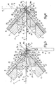
- figures 1 and 2 show a side view of the bending assembly made according to the present invention to two different operating modes;
- figures 3 and 4 show a cross-sectional view of the bending assembly shown respectively in figure 1 and 2; and
- figures 5 and 6 show a cross-sectional view of a further embodiment of the bending assembly in figure 3 and 4.
- With reference to figures from 1 to 4, number 1 indicates a
metal plate 2 bending assembly adapted to bend anend portion 3 of themetal plate 2 with respect to a main portion 4 according to a predetermined bending angle. - In greater detail, non-deformed
metal plate 2 presents a laying plane P; after deformation, the main portion 4 still lays on plane P while theend portion 3 is bent with respect to plane P according to said bending angle. - Assembly 1 essentially comprises a pair of
constraint devices metal plate 2 in a predetermined position, and first andsecond bending tool respective portion respective device respective edge opposite sides end portion 3 during a bending operation. -
Constraint devices 5, 6 (only partially shown in the attached figures) are arranged on opposite sides of the plane P and reciprocally define anadvancement plane 17 of themetal plate 2, which presents an open end to allow feeding of themetal plate 2. - The
constraint devices metal plate 2 is clamped in a certain position, and a second position, in whichmetal plate 2 is free to advance parallelly to plane P according to direction A. - More precisely,
constraint devices first surfaces 15, which at the first position, on side opposite to the open end ofcompartment 17, cooperate with respective opposite side bands ofmetal plate 2 so as to clamp themetal plate 2 in the predetermined position; otherwise, thefirst surfaces 15, at the second position, are distanced so as to allow the advancement of themetal plate 2 itself. - In particular,
constraint device 6 is fixed whileconstraint device 5 is moveable so as to reciprocatingly move with alternating translational motion along a direction parallel to plane P. -
Constraint devices flat walls 16 adapted to each cooperate withportions respective tool - In particular,
surfaces 15 are arranged parallelly with respect to a laying plane P of the non-deformed metal plate whilewalls 16 are inclined with respect to plane P. - Each
tool respective portion respective portion -
Portions edge 14a whileportions edge 14b. -
Tools tools portion 3 on theother tool - More precisely,
edge tool edge tool metal plate 3 itself before bending ofportion 3. - In particular,
edge tool edge tool -
Portions 10 with 12 and 11 with 13 are arranged parallelly towall 16 ofconstraint devices edges regions - With reference to the configuration shown in figures 1 and 3,
tool 9 acts as bender andtool 8 acts as reference. - More precisely,
portion 3 ofmetal plate 2 cooperates, on one only side, withedge 14b oftool 9 acting as bender, while a region adjacent toportion 3 cooperates, on both sides, withedge 14a oftool 8 acting as reference and withedge 14b oftool 9 acting as bender. - In this way,
tool 9 acting as bender turns about an axis B orthogonal to plane P essentially coinciding with a segment common toportion 3 and to the adjacent region so thatedge 14b bends portion 3 againsttool 8 acting as reference. - With reference to the configuration shown in figures 2 and 4,
tool 8 acts as bender andtool 9 acts as reference. - More precisely,
portion 3 ofmetal plate 2 cooperates, on one only side, withedge 14a oftool 8 acting as bender while a region adjacent toportion 3 cooperates, on both of its sides, withedge 14b oftool 9 acting as reference and withedge 14a oftool 8 acting as bender. - In this way,
tool 8 acting as bender turns about an axis B orthogonal to plane P essentially coinciding with a segment common toportion 3 and to the adjacent region so thatedge 14a bends portion 3 againsttool 9 acting as reference. - In both the aforesaid configurations,
bending tool wall 16 of therespective device respective edge 14b bends portion 3 stopping at the required angle. -
Tools constraint devices - If the length of the machine is short, the linkages may be replaced by two bearings at the ends.
- Advantageously, assembly 1 comprises a connection assembly 20 (figures 3 and 4) of each
tool respective constraint device connection assembly 20 joins, at each of the aforesaid configurations, the tool acting asreference respective constraint device bender respective constraint device bending tool end portion 3. - More in detail,
connection assembly 20 comprises a pair ofwedges 21, 22 (figures 3 and 4), each of which is fixed in agroove constraint device respective constraint device respective tool wedge respective groove 25 throughly made in therespective tool - With reference to figures 3 and 4, each
wedge flat surface 27 arranged orthogonally in use to plane P and by aflat surface 28 arranged in use inclined with respect to plane P and parallel to wall 16; eachwedge surfaces surfaces - In particular, each
surface 29 extends parallelly to plane P, comprises a respectivefirst segment 31 cooperating with arespective surface 32 delimiting therespective groove 23 and a respectivesecond segment 33 protruding from therespective device respective tool - Each
surface 30 comprisesrespective end segments intermediate segment 36 orthogonal to plane P and joiningsegments - Each
segment 34 is further distanced from plane P than therespective segment 36 so thatwedge - Each
segment portion 38 of eachsegment 35 cooperate with a respective complementary shapedsurface 37, which delimitsgroove 23 on opposite side ofsurface 32. -
Residual portion 39 of eachsegment 35 protrudes from therespective element respective tool - Each
groove 25 is delimited, on opposite sides, by arespective surface 40 orthogonal to therespective wall respective surface 41, which comprises aparallel segment 42, whentool respective wall - Each
segment 42 is adapted to cooperate with therespective portion 39 when therespective tools respective portion respective portion - In this way, when
tools respective groove 25 twotriangular cavities 44 withingrooves 25 are defined; in particular, eachcavity 44 is delimited byrespective wall respective segment 42 and byrespective portion 38, and is shaped so as to avoid that during distancing of eachtool respective constraint device respective surface 41 knocks against therespective wedge - In particular, each segment 43 is completely contained within a respective circle C having as centre axis B and having radius equal to the distance between axis B and
segment 42. - In use,
metal plate 2 is advanced incompartment 17 according to direction A whiledevices - Once
metal plate 2 reaches its predetermined position,device 5 approachesconstraint device 6 orthogonally with respect to plane P so thatsurfaces 15clamp metal plate 2 on opposite side bands ofmetal plate 2 itself. - At this point,
constraint devices end portion 3 protrudes from the opposite side ofcompartment 17 with respect toconstraint devices - The
end portion 3 may be bent towardsconstraint device 5 by arrangingtools tool 9 acts as bender andtool 8 acts as reference (figures 1 and 3). - Alternatively, (figures 2 and 4), the end portion may be bent towards
constraint device 6 by arrangingtools tool 8 acts as bender andtool 9 acts as reference. - The operation of unit 1 is described with reference to the first configuration.
-
Tool 8 acting as reference is connected respectively toconstraint device 5 by means ofwedge 21, which is fastened withingroove 23 ofconstraint device 5 itself and is engaged bygroove 25 oftool 8 itself. -
Segment 31 ofsurface 29 cooperates withsurface 32 ofgroove 23 whilesegments portion 38 of eachsegment 36 cooperate withsurface 37 ofgroove 23. -
Portion 39 of eachsegment surface 35 protrudes from therespective wedge 21 and is accommodated withingroove 25 of the tool acting as reference. - At such first configuration, the
end portion 3 cooperates only withedge 14b while the region adjacent to endportion 3 itself is clamped, on its opposite sides, betweenedges -
Edge 14b is also advanced along direction A with respect toedge 14a. - Therefore,
tool 9 is free to turn about axis B so that therespective edge 14b bends theend portion 3 by the required angle. - In particular,
wedge 21 effectively maintains coplanar the resting surface oftool 8 acting as reference againstedge 14a during the entire bending step by contrasting the force exerted bytool 9 acting as bender. - At this point,
tool 9 acting as bender returns to home position andconstraint device 5 withtool 8 is distanced fromconstraint device 6 so as to allow advancement ofmetal plate 2 along direction A. - Bending of the
end portion 3 bytool 8 acting as bender andtool 9 acting as reference is entirely similar and is not described because not necessary for understanding the present invention. - With reference to figures 5 and 6, 1' as a whole shows a bending assembly according to a different embodiment of the present invention.
- Assembly 1' is similar to assembly 1 and only the differences thereof will be described; corresponding or equivalent parts of assembly 1 and 1' will be indicated where possible by the same numbers.
- In particular, segments 35' of surface 30' of each wedge 21', 22' present on a part opposite to
segment 36, an end portion 50' slanted with respect to plane P by an angle α. - For the purpose of cooperating perfectly with respective segment 35', each segment 42' of surface 41' delimiting
groove 25 is inclined by a same angle α with respect to plane P. - Preferably, angle α is from zero to forty-five degrees.
- The operation of assembly 1' is entirely identical to the operation of assembly 1 and therefore is not described.
- From an examination of the features of assembly 1, 1' and of the method according to the present invention, the advantages that it allows to obtain are apparent.
- In particular, assembly 1, 1' according to the invention allows to bend the
end portion 3 with respect to main portion 4 on both sides ofmetal plate 2 making any bending angle with minimum joints with high repeatability. - Indeed,
wedges constraint device respective tool end portion 3 folded towardsrespective wall 16. - At the same time,
wedges tool respective wall 16 to perform a bending operation. - In this way, it is possible to maintain, during the bending operation, constantly parallel the laying of
edge tool surface 15 of therespective constraint device - Furthermore, it is possible to obtain high bending angles without over stressing
tools wedges tools respective constraint devices - It is apparent that changes and variations can be made to the assembly 1, 1' and to the method of the invention without departing from the scope of protection of the claims.
said bending tool being turnable, in both said configurations, about an axis essentially coinciding with a common segment between said regions of said metal plate so that the respective edge bends said region to be bent against said reference tool;
characterised in that it comprises connection means of each said tool to a respective clamping element; said connection means connecting, at each of said configurations, said reference tool and the respective clamping element in a fixed way, and said bending tool and the respective clamping element so that said bending tool can be actuated to act on said region to be bent.
Claims (9)
- A bending assembly (1, 1') of a metal plate (2) comprising;- a first and a second clamping element (5, 6) arranged on opposite sides of said metal plate (2) to clamp it on its opposite sides;- a first and a second tool (8, 9) arranged on opposite sides of said metal plate (2) and on a same side of said first and second clamping element (5, 6); said first and second tools (8, 9) comprising respective edges (14a, 14b) cooperating with respective opposite sides of said metal plate (2);said first and second tool (8, 9) being available in two configurations, at each of which a region (3) to be bent of the metal plate (2) cooperates, on one only side, with said edge (14a; 14b) of one of said tools (8; 9) performing the function of bender while an adjacent region of said metal plate (2) cooperates, on both sides, with an edge (14a; 14b) of said bending tool (8) with the edge (14b; 14a) of the other of said tools (9; 8) performing the function of reference; said region adjacent to said metal plate (2) cooperating, on both said sides, with respective walls (15) of a respective constraint device (5; 6);
said bending tool (8; 9) being turnable, in both said configurations, about an axis (B) essentially coinciding with a common segment between said regions of said metal plate (2) so that the respective edge (14a; 14b) bends said region to be bent (3) against said reference tool (9, 8);
characterised in that it comprises connection means (20) of each said tool (8, 9) to a respective clamping element (5, 6); said connection means (20) connecting, at each of said configurations, said reference tool (9; 8) and the respective clamping element (6, 5) in a fixed way, and said bending tool (8, 9) and the respective clamping element (5, 6) so that the bending tool (8; 9) can be actuated to act on said region to be bent (3). - A bending assembly (1, 1') according to claim 1, characterised in that said edge (14a; 14b) of said bending tool (8, 9) and said edge (14b; 14a) of said reference tool (9, 8) are parallel and reciprocally staggered before bending of said region (3) to be bent of said metal plate (2).
- A bending assembly according to claim 2, characterised in that said edge (14a; 14b) of said bending tool (8, 9) is advanced with respect to said edge (14b; 14a) of said reference tool (9; 8) according to a direction (A) of advancement of said metal plate (2) before bending of said region (3) to be bent of said metal plate (2)
- An assembly (1, 1') according to any one of the preceding claims, characterised in that said connection means (20) comprise a pair of wedges (21, 22, 21', 22'), each of which is inserted between a respective said tool (8, 9) and a respective clamping element (5; 6).
- An assembly (1, 1') according to claim 4, characterised in that each wedge (21, 22, 21', 22') is inserted between the respective said tool (8; 9) and the respective clamping element (5, 6) parallelly to said direction (A).
- A bending assembly according to claim 5, characterised in that each said wedge (21, 22, 21', 22') is accommodated in a respective groove (23, 24) of said clamping element (5, 6) so as to protrude from said respective seat (16) and to be couplable to the respective tool (8, 9).
- A bending assembly according to claim 5 or 6, characterised in that each tool (8, 9) comprises a respective groove (25) adapted to be engaged by the respective wedge (21, 22, 21', 22'); said groove (25) being delimited by respective first surface (42, 42') adapted to cooperate with said wedge (21, 22, 21', 22') and slanted with respect to a laying plane (P) of said non-deformed metal plate (2) by an angle (α) from 0 to 45 degrees.
- A bending assembly according to claim 7, characterised in that each groove (25) is further delimited by a respective second surface (43) adjacent to said first surface (42, 42') and comprised in a circle (C) having centre on an axis of rotation (B) of the respective tool (8, 9) and having radius equal to the distance between said first plane (P) and said relative first surface (42, 42').
- A metal plate (2) bending method comprising the steps of:- clamping said metal plate (2) by means of a first and second clamping element (5, 6) arranged on opposite sides of said metal plate (3);- arranging a first and second tool (8, 9) on opposite sides of said metal plate (2) and on the same sides of said first and second clamping element (5; 6) so that the respective edges (14a; 14b) cooperate with respective opposite sides of said metal plate (2); said first and second tool (8, 9) being available in two configurations, at each of which a region (3) to be bent of the metal plate (2) cooperates, on one only side, with said edge (14a) of one of said tools (8; 9) performing the function of bender while an adjacent region of said metal plate (2) cooperates, on both sides, with the edge (14a; 14b) of said bending tool (8) and with the edge (14a; 14b) of the other of said tools (8; 9) performing the function of reference; said adjacent region cooperating, in each of said configurations, on both said sides, with respective walls (15) of said constraint devices (5; 6)- turning said bending tool (8; 9) about an axis (B) essentially coinciding with a common segment between said regions of said metal plate (2) so that the respective edge (14a; 14b) bends said region to be bent (3) against said reference tool (9, 8);characterised in that it comprises the step of connecting each said tool (8; 9) to a respective clamping element (5, 6) so that at each of said configurations said reference tool (9; 8) and the respective clamping element (6; 5) are connected in fixed way and that said bending tool (8; 9) can be actuated to act on said region (3) to be bent.
Priority Applications (2)
| Application Number | Priority Date | Filing Date | Title |
|---|---|---|---|
| DE602006003536T DE602006003536D1 (en) | 2006-05-08 | 2006-05-08 | Device and method for bending a sheet |
| EP06425311A EP1854564B1 (en) | 2006-05-08 | 2006-05-08 | Metal plate bending assembly and method |
Applications Claiming Priority (1)
| Application Number | Priority Date | Filing Date | Title |
|---|---|---|---|
| EP06425311A EP1854564B1 (en) | 2006-05-08 | 2006-05-08 | Metal plate bending assembly and method |
Publications (2)
| Publication Number | Publication Date |
|---|---|
| EP1854564A1 true EP1854564A1 (en) | 2007-11-14 |
| EP1854564B1 EP1854564B1 (en) | 2008-11-05 |
Family
ID=37057111
Family Applications (1)
| Application Number | Title | Priority Date | Filing Date |
|---|---|---|---|
| EP06425311A Ceased EP1854564B1 (en) | 2006-05-08 | 2006-05-08 | Metal plate bending assembly and method |
Country Status (2)
| Country | Link |
|---|---|
| EP (1) | EP1854564B1 (en) |
| DE (1) | DE602006003536D1 (en) |
Cited By (4)
| Publication number | Priority date | Publication date | Assignee | Title |
|---|---|---|---|---|
| EP2014381A2 (en) | 2007-07-13 | 2009-01-14 | Franze Reinhard | Sheet-metal bending machine, preferentially hydro-powered machine, and a method of its operation |
| EP3706930A4 (en) * | 2017-11-06 | 2021-07-07 | Hershberger, Nelson Dwayne | BENDING MACHINE |
| US11612925B2 (en) * | 2018-01-17 | 2023-03-28 | EVOBEND GmbH | Bending machine and method for bending a workpiece out of a flat material |
| EP4186607A1 (en) * | 2021-11-26 | 2023-05-31 | Sucorema Subcontrato Fabricação e Reparação de Mãquinas Lda | Sheet metal folding machine |
Citations (1)
| Publication number | Priority date | Publication date | Assignee | Title |
|---|---|---|---|---|
| US4043165A (en) * | 1976-09-15 | 1977-08-23 | The Boeing Company | Three-point, air-bending sheet metal bender |
-
2006
- 2006-05-08 EP EP06425311A patent/EP1854564B1/en not_active Ceased
- 2006-05-08 DE DE602006003536T patent/DE602006003536D1/en not_active Expired - Fee Related
Patent Citations (1)
| Publication number | Priority date | Publication date | Assignee | Title |
|---|---|---|---|---|
| US4043165A (en) * | 1976-09-15 | 1977-08-23 | The Boeing Company | Three-point, air-bending sheet metal bender |
Cited By (6)
| Publication number | Priority date | Publication date | Assignee | Title |
|---|---|---|---|---|
| EP2014381A2 (en) | 2007-07-13 | 2009-01-14 | Franze Reinhard | Sheet-metal bending machine, preferentially hydro-powered machine, and a method of its operation |
| EP2014381A3 (en) * | 2007-07-13 | 2011-03-23 | Reinhard Franze | Sheet-metal bending machine, preferentially hydro-powered machine, and a method of its operation |
| US8061175B2 (en) | 2007-07-13 | 2011-11-22 | Reinhard Franze | Sheet-metal bending machine, preferentially hydro-powered machine, and a method of its operation |
| EP3706930A4 (en) * | 2017-11-06 | 2021-07-07 | Hershberger, Nelson Dwayne | BENDING MACHINE |
| US11612925B2 (en) * | 2018-01-17 | 2023-03-28 | EVOBEND GmbH | Bending machine and method for bending a workpiece out of a flat material |
| EP4186607A1 (en) * | 2021-11-26 | 2023-05-31 | Sucorema Subcontrato Fabricação e Reparação de Mãquinas Lda | Sheet metal folding machine |
Also Published As
| Publication number | Publication date |
|---|---|
| EP1854564B1 (en) | 2008-11-05 |
| DE602006003536D1 (en) | 2008-12-18 |
Similar Documents
| Publication | Publication Date | Title |
|---|---|---|
| JP4999636B2 (en) | Assembly device for constructing a locking mechanism for preventing circumferential displacement of a sealing element arranged on the front side of a rotor of a turbine, and method for constructing such a locking mechanism | |
| US8474299B2 (en) | Crimping tool | |
| JP5233682B2 (en) | Bending machine | |
| US9384921B2 (en) | Break-off-resistant control device | |
| JP2020520629A (en) | Method and apparatus for deforming U-shaped electric conductor | |
| FI90901B (en) | Position of detachable with a coupling piece with interconnecting profile bars | |
| EP1854564B1 (en) | Metal plate bending assembly and method | |
| EP1980337A1 (en) | Clamping device for bending tools | |
| US20190081525A1 (en) | Covering element for covering a slot between two adjacent tooth tips of an electromagnetic machine | |
| WO2016100087A1 (en) | Apparatus and method for impact forming a cotter pin | |
| JP5975061B2 (en) | Caulking device and caulking method | |
| JP2010214469A (en) | Press brake for bending sheet | |
| US20060000255A1 (en) | Method for performing a 180 degree hem and apparatus for performing the same | |
| CN106825231B (en) | Tool for a stamping machine for reshaping a part of a plate-shaped workpiece and method for using same | |
| JP6562654B2 (en) | Sheet processing device | |
| US20150107981A1 (en) | Circuit breaker and production method of pin for circuit breaker's switching mechanism | |
| JP2017075501A5 (en) | ||
| JP3496507B2 (en) | Metal plate processing equipment | |
| JPS6134815B2 (en) | ||
| KR100602740B1 (en) | Draw guide and procedure for the realization and for the assembly thereof | |
| CN113732128A (en) | A seamless bending device and bending method | |
| KR101636217B1 (en) | Elbow pipe manufacturing method and a manufacturing apparatus | |
| KR101653378B1 (en) | Rivetting Apparatus having Multiple Rivetting Block | |
| KR20120074864A (en) | Strip connector | |
| EP4368328B1 (en) | Weld tip remover |
Legal Events
| Date | Code | Title | Description |
|---|---|---|---|
| PUAI | Public reference made under article 153(3) epc to a published international application that has entered the european phase |
Free format text: ORIGINAL CODE: 0009012 |
|
| 17P | Request for examination filed |
Effective date: 20070419 |
|
| AK | Designated contracting states |
Kind code of ref document: A1 Designated state(s): AT BE BG CH CY CZ DE DK EE ES FI FR GB GR HU IE IS IT LI LT LU LV MC NL PL PT RO SE SI SK TR |
|
| AX | Request for extension of the european patent |
Extension state: AL BA HR MK YU |
|
| GRAP | Despatch of communication of intention to grant a patent |
Free format text: ORIGINAL CODE: EPIDOSNIGR1 |
|
| GRAS | Grant fee paid |
Free format text: ORIGINAL CODE: EPIDOSNIGR3 |
|
| AKX | Designation fees paid |
Designated state(s): CH DE IT LI |
|
| GRAA | (expected) grant |
Free format text: ORIGINAL CODE: 0009210 |
|
| AK | Designated contracting states |
Kind code of ref document: B1 Designated state(s): CH DE IT LI |
|
| REG | Reference to a national code |
Ref country code: CH Ref legal event code: EP |
|
| REF | Corresponds to: |
Ref document number: 602006003536 Country of ref document: DE Date of ref document: 20081218 Kind code of ref document: P |
|
| REG | Reference to a national code |
Ref country code: CH Ref legal event code: NV Representative=s name: NOVAGRAAF INTERNATIONAL SA |
|
| PLBE | No opposition filed within time limit |
Free format text: ORIGINAL CODE: 0009261 |
|
| STAA | Information on the status of an ep patent application or granted ep patent |
Free format text: STATUS: NO OPPOSITION FILED WITHIN TIME LIMIT |
|
| 26N | No opposition filed |
Effective date: 20090806 |
|
| PGFP | Annual fee paid to national office [announced via postgrant information from national office to epo] |
Ref country code: DE Payment date: 20090720 Year of fee payment: 4 |
|
| REG | Reference to a national code |
Ref country code: CH Ref legal event code: PL |
|
| PG25 | Lapsed in a contracting state [announced via postgrant information from national office to epo] |
Ref country code: LI Free format text: LAPSE BECAUSE OF NON-PAYMENT OF DUE FEES Effective date: 20100531 Ref country code: CH Free format text: LAPSE BECAUSE OF NON-PAYMENT OF DUE FEES Effective date: 20100531 |
|
| PG25 | Lapsed in a contracting state [announced via postgrant information from national office to epo] |
Ref country code: DE Free format text: LAPSE BECAUSE OF NON-PAYMENT OF DUE FEES Effective date: 20101201 |
|
| PGFP | Annual fee paid to national office [announced via postgrant information from national office to epo] |
Ref country code: IT Payment date: 20130522 Year of fee payment: 8 |
|
| PG25 | Lapsed in a contracting state [announced via postgrant information from national office to epo] |
Ref country code: IT Free format text: LAPSE BECAUSE OF NON-PAYMENT OF DUE FEES Effective date: 20140508 |