EP1856323B1 - Device and method for solar panels to a roof - Google Patents
Device and method for solar panels to a roof Download PDFInfo
- Publication number
- EP1856323B1 EP1856323B1 EP06716665.2A EP06716665A EP1856323B1 EP 1856323 B1 EP1856323 B1 EP 1856323B1 EP 06716665 A EP06716665 A EP 06716665A EP 1856323 B1 EP1856323 B1 EP 1856323B1
- Authority
- EP
- European Patent Office
- Prior art keywords
- base element
- roof
- mounting rail
- hook
- receiving space
- Prior art date
- Legal status (The legal status is an assumption and is not a legal conclusion. Google has not performed a legal analysis and makes no representation as to the accuracy of the status listed.)
- Expired - Lifetime
Links
Images


Classifications
-
- F—MECHANICAL ENGINEERING; LIGHTING; HEATING; WEAPONS; BLASTING
- F24—HEATING; RANGES; VENTILATING
- F24S—SOLAR HEAT COLLECTORS; SOLAR HEAT SYSTEMS
- F24S25/00—Arrangement of stationary mountings or supports for solar heat collector modules
- F24S25/60—Fixation means, e.g. fasteners, specially adapted for supporting solar heat collector modules
- F24S25/61—Fixation means, e.g. fasteners, specially adapted for supporting solar heat collector modules for fixing to the ground or to building structures
- F24S25/613—Fixation means, e.g. fasteners, specially adapted for supporting solar heat collector modules for fixing to the ground or to building structures in the form of bent strips or assemblies of strips; Hook-like connectors; Connectors to be mounted between building-covering elements
-
- F—MECHANICAL ENGINEERING; LIGHTING; HEATING; WEAPONS; BLASTING
- F24—HEATING; RANGES; VENTILATING
- F24S—SOLAR HEAT COLLECTORS; SOLAR HEAT SYSTEMS
- F24S25/00—Arrangement of stationary mountings or supports for solar heat collector modules
- F24S25/30—Arrangement of stationary mountings or supports for solar heat collector modules using elongate rigid mounting elements extending substantially along the supporting surface, e.g. for covering buildings with solar heat collectors
- F24S25/33—Arrangement of stationary mountings or supports for solar heat collector modules using elongate rigid mounting elements extending substantially along the supporting surface, e.g. for covering buildings with solar heat collectors forming substantially planar assemblies, e.g. of coplanar or stacked profiles
-
- H—ELECTRICITY
- H02—GENERATION; CONVERSION OR DISTRIBUTION OF ELECTRIC POWER
- H02S—GENERATION OF ELECTRIC POWER BY CONVERSION OF INFRARED RADIATION, VISIBLE LIGHT OR ULTRAVIOLET LIGHT, e.g. USING PHOTOVOLTAIC [PV] MODULES
- H02S20/00—Supporting structures for PV modules
- H02S20/20—Supporting structures directly fixed to an immovable object
- H02S20/22—Supporting structures directly fixed to an immovable object specially adapted for buildings
- H02S20/23—Supporting structures directly fixed to an immovable object specially adapted for buildings specially adapted for roof structures
-
- F—MECHANICAL ENGINEERING; LIGHTING; HEATING; WEAPONS; BLASTING
- F24—HEATING; RANGES; VENTILATING
- F24S—SOLAR HEAT COLLECTORS; SOLAR HEAT SYSTEMS
- F24S25/00—Arrangement of stationary mountings or supports for solar heat collector modules
- F24S25/60—Fixation means, e.g. fasteners, specially adapted for supporting solar heat collector modules
- F24S2025/6002—Fixation means, e.g. fasteners, specially adapted for supporting solar heat collector modules by using hooks
-
- F—MECHANICAL ENGINEERING; LIGHTING; HEATING; WEAPONS; BLASTING
- F24—HEATING; RANGES; VENTILATING
- F24S—SOLAR HEAT COLLECTORS; SOLAR HEAT SYSTEMS
- F24S25/00—Arrangement of stationary mountings or supports for solar heat collector modules
- F24S25/60—Fixation means, e.g. fasteners, specially adapted for supporting solar heat collector modules
- F24S2025/6004—Fixation means, e.g. fasteners, specially adapted for supporting solar heat collector modules by clipping, e.g. by using snap connectors
-
- Y—GENERAL TAGGING OF NEW TECHNOLOGICAL DEVELOPMENTS; GENERAL TAGGING OF CROSS-SECTIONAL TECHNOLOGIES SPANNING OVER SEVERAL SECTIONS OF THE IPC; TECHNICAL SUBJECTS COVERED BY FORMER USPC CROSS-REFERENCE ART COLLECTIONS [XRACs] AND DIGESTS
- Y02—TECHNOLOGIES OR APPLICATIONS FOR MITIGATION OR ADAPTATION AGAINST CLIMATE CHANGE
- Y02B—CLIMATE CHANGE MITIGATION TECHNOLOGIES RELATED TO BUILDINGS, e.g. HOUSING, HOUSE APPLIANCES OR RELATED END-USER APPLICATIONS
- Y02B10/00—Integration of renewable energy sources in buildings
- Y02B10/10—Photovoltaic [PV]
-
- Y—GENERAL TAGGING OF NEW TECHNOLOGICAL DEVELOPMENTS; GENERAL TAGGING OF CROSS-SECTIONAL TECHNOLOGIES SPANNING OVER SEVERAL SECTIONS OF THE IPC; TECHNICAL SUBJECTS COVERED BY FORMER USPC CROSS-REFERENCE ART COLLECTIONS [XRACs] AND DIGESTS
- Y02—TECHNOLOGIES OR APPLICATIONS FOR MITIGATION OR ADAPTATION AGAINST CLIMATE CHANGE
- Y02B—CLIMATE CHANGE MITIGATION TECHNOLOGIES RELATED TO BUILDINGS, e.g. HOUSING, HOUSE APPLIANCES OR RELATED END-USER APPLICATIONS
- Y02B10/00—Integration of renewable energy sources in buildings
- Y02B10/20—Solar thermal
-
- Y—GENERAL TAGGING OF NEW TECHNOLOGICAL DEVELOPMENTS; GENERAL TAGGING OF CROSS-SECTIONAL TECHNOLOGIES SPANNING OVER SEVERAL SECTIONS OF THE IPC; TECHNICAL SUBJECTS COVERED BY FORMER USPC CROSS-REFERENCE ART COLLECTIONS [XRACs] AND DIGESTS
- Y02—TECHNOLOGIES OR APPLICATIONS FOR MITIGATION OR ADAPTATION AGAINST CLIMATE CHANGE
- Y02E—REDUCTION OF GREENHOUSE GAS [GHG] EMISSIONS, RELATED TO ENERGY GENERATION, TRANSMISSION OR DISTRIBUTION
- Y02E10/00—Energy generation through renewable energy sources
- Y02E10/40—Solar thermal energy, e.g. solar towers
- Y02E10/47—Mountings or tracking
-
- Y—GENERAL TAGGING OF NEW TECHNOLOGICAL DEVELOPMENTS; GENERAL TAGGING OF CROSS-SECTIONAL TECHNOLOGIES SPANNING OVER SEVERAL SECTIONS OF THE IPC; TECHNICAL SUBJECTS COVERED BY FORMER USPC CROSS-REFERENCE ART COLLECTIONS [XRACs] AND DIGESTS
- Y02—TECHNOLOGIES OR APPLICATIONS FOR MITIGATION OR ADAPTATION AGAINST CLIMATE CHANGE
- Y02E—REDUCTION OF GREENHOUSE GAS [GHG] EMISSIONS, RELATED TO ENERGY GENERATION, TRANSMISSION OR DISTRIBUTION
- Y02E10/00—Energy generation through renewable energy sources
- Y02E10/50—Photovoltaic [PV] energy
Definitions
- the invention relates to a device for fixing solar panels to a roof, comprising at least one base element connectable to the roof, and a mounting rail connectable to the base element for fixing to a solar panel, wherein the mounting rail is provided with a receiving space for receiving at least a part of mechanical fixing means connected to the solar panel.
- the invention also relates to an assembly of such devices.
- the invention further relates to a method for fixing objects, in particular solar panels, to a roof.
- the known fixing device herein comprises a plurality of profiles which are fixed by means of screws to one or more tile battens, and a mounting rail which is fixed to the profiles by means of - usually specifically designed - mechanical fixing elements such as for instance bolts, nuts and so on.
- the actual object can herein be arranged on the mounting rail.
- the known fixing device does however have a number of drawbacks.
- a significant drawback of the known device is that the mounting of an object on the roof is a relatively time-consuming activity, because of the relatively high number of mechanical fixing elements required. Special tools are moreover often required, such as for instance a right-angle screwing machine, for mounting the device correctly. In addition, mounting of the device can usually only be carried out by specialist professionals, which generally makes mounting of the object relatively expensive.
- DE 19811399 A1 discloses an arrangement for the fastening to the roof of plate-shaped photovoltaic solar modules designed as tiles or stones of an inclined building roof overlapping at least partially.
- DE 29817311 U1 discloses a solar element fixing device for mounting solar elements above a roof covering.
- the solar element fixing device comprises a clip which can be fastened to the roof covering.
- WO 99/17063 A discloses a fixing device for solar modules, consisting of a locating part and fixing means.
- the locating part has at least one recess on its top part facing the solar module.
- DE 29912699 U1 discloses an arrangement for fastening solar panels, which comprises a profile frame and a base profile which are coupled via a mounting element.
- US 2004/221524 A1 discloses a bracket for mounting a photovoltaic module to a support structure.
- DE 10132557 A1 discloses a mounting system for attaching photovoltaic modules.
- the device has a base body, a tooth-shaped surface section, a lateral bolt channel and a water outlet channel.
- the invention has for its object to provide an improved device of the type stated in the preamble which can be fixed relatively simply and quickly to a roof.
- the invention provides for this purpose a device as stated in claim 1.
- a snap connection often also referred to as a click connection
- the number of components required for mounting the device according to the invention can be significantly reduced, which considerably facilitates and, in particular, simplifies and speeds up mounting.
- specialist professionals are not required for the purpose of realizing the coupling between the base element and the mounting rail.
- Tests have shown that with the relatively rapid and simplified mounting of the device according to the invention a cost-saving of about 40% can be achieved compared to the average cost of mounting a conventional device known from the prior art; and the time required for mounting the device according to the invention is generally reduced by about 60% compared to the time required for mounting the conventional device.
- This reduced mounting time, and therefore working time is generally also advantageous from a working safety viewpoint, since a fitter need only be on usually dangerous pitched roofs for a relatively short period of time.
- the device will generally be applied for mounting solar panels on a tiled roof. It is however also possible to envisage arranging other objects, such as for instance a solar boiler, on the roof by means of the device according to the invention.
- the base element preferably comprises coupling means for co-action with mating means forming part of the mounting rail.
- Both the coupling means and the mating means can herein be of very diverse design.
- the coupling means and the mating means are however preferably adapted to mutually realize a relatively strong, stable and reliable snap connection, so as to be able to prevent, or at least counter, undesired uncoupling of the object relative to the roof.
- the base element and the mounting rail are adapted for mutually releasable coupling. It is then made possible to disassemble an already mounted device in relatively simple manner. A releasable coupling moreover facilitates maintenance and or replacement operations on parts of the device.
- the snap connection is preferably adapted for two-dimensional fixation of the relative orientation of the base element and the mounting rail. One dimension is herein not fixed and therefore left free, whereby the relative orientation between the base element and the mounting rail can be changed in one-dimensional (linear) manner, wherein the base element is for instance linearly slidable along the mounting rail and vice versa. Such a fixation is usually advantageous since alignment of the base element relative to the roof can be realized relatively simply in this manner.
- the base element is provided with a substantially hook-shaped member adapted for co-action with a part of the roof, in particular with a tile batten arranged on the roof.
- a substantially hook-shaped member adapted for co-action with a part of the roof, in particular with a tile batten arranged on the roof.
- a strong and reliable coupling can be realized between the roof and the base element merely by hooking the base element, or at least the hook-shaped member thereof, behind a tile batten or any other suitable element forming part of the roof.
- This preferred embodiment of the base element can therefore not only be mounted relatively quickly and simply, but also has the advantage that the tile batten is not damaged, whereby the tile batten is not (any longer) unnecessarily weakened.
- the base element is fixed to the tile batten by means of mechanical fixing elements, such as screws, often resulting in splitting and/or cracking of the tile batten, whereby the tile batten and therefore the mutual coupling between the base element and the tile batten may be considerably weakened.
- the hook-shaped member is provided with at least one at least partially profiled side. The friction between the roof and the base element can be increased by the profiled side, which generally increases the strength of the coupling between the roof and the base element.
- the profile is preferably formed by a sawtooth profile adapted for relatively intensive co-action with a part of the roof, in particular a tile batten.
- the volume of a receiving space enclosed by the substantially hook-shaped member can preferably be changed.
- the hook-shaped member acquires a certain adaptive capacity, wherein the effective dimensioning of the hook-shaped member can be geared to the tile batten in question.
- the top structure can be very diverse in nature, but is preferably formed by a mounting rail to which the object, in particular the solar panel, can be fixed.
- the advantage of a mounting rail is that the relative orientation between the mounting rail and the object can be changed - in general linearly - to thus allow the object to be positioned and aligned in ideal manner.
- the device preferably comprises a plurality of base elements, which base elements are adapted for simultaneous co-action with the top structure. The mutual distance of the base elements can vary here, but is for instance about one metre.
- the base element is formed by an extrusion profile.
- the extrusion profile will usually be formed first of all here, whereafter the extrusion profile is divided, for instance by means of sawing, into a plurality of parts forming a corresponding number of base elements.
- Forming the base element from an extrusion profile has the important advantage that in this way a relatively strong base element can be provided compared to base elements manufactured by means of casting, injection moulding and folding, which increases the strength of the device.
- the invention also relates to an assembly of a plurality of devices according to the invention, wherein the assembly is adapted to support at least one object, in particular a solar panel.
- the relative orientation of the components of the assembly can herein be very diverse in nature.
- the top structures of the devices preferably have a substantially parallel orientation relative to each other.
- the distance between the mounting rails can however vary here, although the mutual distance between the mounting rails is preferably such that about four base elements can be arranged per m 2 , in order to be able to achieve a stable and durable support of an object, in particular a solar panel, of average size.
- the invention further relates to a method for fixing solar panels, to a roof, according to claim 11. Because, due to forming of the snap connection, additional mechanical fixing elements are not required for mounting the device, and thereby the object, on the roof, the object can be arranged relatively quickly and efficiently on the roof.
- step A) a plurality of base elements will usually be arranged, and during step B) a plurality of mounting rails will be coupled to the base elements, in order to allow a reliable support structure to be generated for the object or the plurality of objects.
- FIG 1a shows a side view of a roof hook 1 of a device according to the invention.
- Roof hook 1 is adapted particularly for coupling to a tile batten of a roof (not shown), wherein roof hook 1 in fact serves as base structure for a mounting rail (see figure 1b ) to which a solar panel or other object can be fixed.
- Roof hook 1 comprises for this purpose a hook-shaped member 2 provided with a profiled inner side 3, wherein hook-shaped member 2 is adapted for co-action with a tile batten (not shown).
- An outer end of roof hook 1 remote from hook-shaped member 2 is provided with coupling means 4 adapted for co-action with mating means forming part of a mounting rail (see figure 1b ).
- Coupling means 4 herein comprise one slightly resilient tongue 5 to enable a snap connection with the mating means to be realized.
- Coupling means 5 further comprise a protruding coupling finger 6, and an intermediate locking element 7 for realizing the coupling.
- Roof hook 1 is manufactured in this exemplary embodiment from an extrusion profile made of aluminium which is particularly characterized by a relatively great strength.
- Figure 1b shows a side view of a mounting rail 8 of a device according to the invention.
- Mounting rail 8 is adapted to be partially enclosed by the resilient tongue 5, wherein a part of tongue 5 can be received in a first receiving space 9 arranged in mounting rail 8.
- Mounting rail 8 is also provided with a second receiving space 10 for accommodating at least a part of the protruding coupling finger 6.
- Mounting rail 8 is further provided with a third receiving space 11 formed by a groove for the purpose of receiving at least a part of locking element 7.
- a side of mounting rail 8 remote from the second receiving space 10 and third receiving space 11 is provided with a fourth receiving space 12 for receiving a part of the object, or in any case at least a part of mechanical fixing means connected to the object, such as for instance optionally be self-tapping screws.
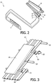
- FIG. 2 shows a perspective view of roof hook 1 according to figure 1a and mounting rail 8 according to figure 1b co-acting with roof hook 1.
- coupling finger 6 is received in the second receiving space 10 of mounting rail 8
- locking element 7 is received in the third receiving space 11 of mounting rail 8.
- Tongue 5 herein encloses a part of the underside of mounting rail 8, wherein an outer end of tongue 5 is received in a first receiving space 9 of mounting rail 8, whereby roof hook 1 and mounting rail 8 are fixed two-dimensionally relative to each other.
- the assembly or support frame of roof hook 1 and the mounting rail 8 coupled to roof hook 1 forms an exemplary embodiment of a device 12 according to the invention.
- Figure 3 shows a perspective view of a solar panel 14 arranged on a tiled roof 13 by means of device 12 according to figure 2 .
- the tiled roof 13 is herein provided with a plurality of tile battens 15 to support a plurality of roof tiles 16. Since no additional mechanical fixing elements are required for mounting the complete device 12 on tiled roof 13, disassembly can be realized relatively quickly and at relatively low cost.
- Figure 4 shows a perspective view of a plurality of solar panels 18 arranged on a tiled roof 17 by means of a plurality of devices 12 according to figure 2 .
- Mounting rails 8 of devices 12 herein either lie mutually in line or have a substantially parallel orientation.
- About four roof hooks 1 will generally be positioned per m 2 of roof surface.
- Fixing of device 12 on tiled roof 17 takes place in accordance with the method shown in figure 4 .
- FIG. 5 shows a side view of an alternative base element 19 for use in a device according to the invention.
- Base element 19 is in fact formed by a roof hook which is structurally very similar to roof hook 1 shown in figure 1a .
- Base element 19 comprises a hook-shaped member 20, which hook-shaped member 20 comprises two hook parts 21a, 21b which are mutually connected by means of a screw connection 22. It is possible in this manner to be able to adapt the width B between the two hook parts 21a, 21b relatively easily to the width of a tile batten situated therebetween (not shown). So as to be able to optimize the coupling between hook-shaped member 20 and the tile batten, both hook parts 21a, 21b are provided with a sawtooth profile 23 a, 23b.
- An outer end of hook-shaped member 20 remote from the base element is provided with coupling means 24 to enable clicking of base element 19 fixedly to a mounting rail (not shown).
- Coupling means 24 are here formed by two coupling members 25a, 25b in mirror image design.
Landscapes
- Engineering & Computer Science (AREA)
- Architecture (AREA)
- Civil Engineering (AREA)
- Structural Engineering (AREA)
- General Engineering & Computer Science (AREA)
- Mechanical Engineering (AREA)
- Sustainable Development (AREA)
- Sustainable Energy (AREA)
- Thermal Sciences (AREA)
- Chemical & Material Sciences (AREA)
- Combustion & Propulsion (AREA)
- Life Sciences & Earth Sciences (AREA)
- Physics & Mathematics (AREA)
- Roof Covering Using Slabs Or Stiff Sheets (AREA)
Description
- The invention relates to a device for fixing solar panels to a roof, comprising at least one base element connectable to the roof, and a mounting rail connectable to the base element for fixing to a solar panel, wherein the mounting rail is provided with a receiving space for receiving at least a part of mechanical fixing means connected to the solar panel. The invention also relates to an assembly of such devices. The invention further relates to a method for fixing objects, in particular solar panels, to a roof.
- Solar panels and solar boilers are increasingly being arranged commercially on roofs, which may or may not be pitched, in order to be able to employ solar energy in relatively simple and advantageous manner for generating electricity or for heating a medium. Such objects are fixed to a roof by means of a fixing device or supporting device. The known fixing device herein comprises a plurality of profiles which are fixed by means of screws to one or more tile battens, and a mounting rail which is fixed to the profiles by means of - usually specifically designed - mechanical fixing elements such as for instance bolts, nuts and so on. The actual object can herein be arranged on the mounting rail. The known fixing device does however have a number of drawbacks. A significant drawback of the known device is that the mounting of an object on the roof is a relatively time-consuming activity, because of the relatively high number of mechanical fixing elements required. Special tools are moreover often required, such as for instance a right-angle screwing machine, for mounting the device correctly. In addition, mounting of the device can usually only be carried out by specialist professionals, which generally makes mounting of the object relatively expensive.
-
DE 19811399 A1 discloses an arrangement for the fastening to the roof of plate-shaped photovoltaic solar modules designed as tiles or stones of an inclined building roof overlapping at least partially. -
DE 29817311 U1 discloses a solar element fixing device for mounting solar elements above a roof covering. The solar element fixing device comprises a clip which can be fastened to the roof covering. -
WO 99/17063 A -
DE 29912699 U1 discloses an arrangement for fastening solar panels, which comprises a profile frame and a base profile which are coupled via a mounting element. -
US 2004/221524 A1 discloses a bracket for mounting a photovoltaic module to a support structure. -
DE 10132557 A1 discloses a mounting system for attaching photovoltaic modules. The device has a base body, a tooth-shaped surface section, a lateral bolt channel and a water outlet channel. - The invention has for its object to provide an improved device of the type stated in the preamble which can be fixed relatively simply and quickly to a roof. The invention provides for this purpose a device as stated in
claim 1. By mutually coupling the base element and the mounting rail by means of a snap connection, often also referred to as a click connection, the number of components required for mounting the device according to the invention can be significantly reduced, which considerably facilitates and, in particular, simplifies and speeds up mounting. Furthermore, specialist professionals are not required for the purpose of realizing the coupling between the base element and the mounting rail. Nor are specific tools necessary to enable realizing of the snap coupling. Tests have shown that with the relatively rapid and simplified mounting of the device according to the invention a cost-saving of about 40% can be achieved compared to the average cost of mounting a conventional device known from the prior art; and the time required for mounting the device according to the invention is generally reduced by about 60% compared to the time required for mounting the conventional device. This reduced mounting time, and therefore working time, is generally also advantageous from a working safety viewpoint, since a fitter need only be on usually dangerous pitched roofs for a relatively short period of time. The device will generally be applied for mounting solar panels on a tiled roof. It is however also possible to envisage arranging other objects, such as for instance a solar boiler, on the roof by means of the device according to the invention. In addition to fixing such objects to a roof, it is also possible to envisage fixing such objects by means of a device according to the invention to for instance an (outside) wall of a property. In order to realize the snap connection the base element preferably comprises coupling means for co-action with mating means forming part of the mounting rail. Both the coupling means and the mating means can herein be of very diverse design. The coupling means and the mating means are however preferably adapted to mutually realize a relatively strong, stable and reliable snap connection, so as to be able to prevent, or at least counter, undesired uncoupling of the object relative to the roof. - In a preferred embodiment of the device according to the invention the base element and the mounting rail are adapted for mutually releasable coupling. It is then made possible to disassemble an already mounted device in relatively simple manner. A releasable coupling moreover facilitates maintenance and or replacement operations on parts of the device. The snap connection is preferably adapted for two-dimensional fixation of the relative orientation of the base element and the mounting rail. One dimension is herein not fixed and therefore left free, whereby the relative orientation between the base element and the mounting rail can be changed in one-dimensional (linear) manner, wherein the base element is for instance linearly slidable along the mounting rail and vice versa. Such a fixation is usually advantageous since alignment of the base element relative to the roof can be realized relatively simply in this manner.
- In the embodiment the base element is provided with a substantially hook-shaped member adapted for co-action with a part of the roof, in particular with a tile batten arranged on the roof. In this manner at least a part of the base element can be enclosed relatively efficiently between tiles on a tiled roof without additional mechanical fixing means being necessary here. A strong and reliable coupling can be realized between the roof and the base element merely by hooking the base element, or at least the hook-shaped member thereof, behind a tile batten or any other suitable element forming part of the roof. This preferred embodiment of the base element can therefore not only be mounted relatively quickly and simply, but also has the advantage that the tile batten is not damaged, whereby the tile batten is not (any longer) unnecessarily weakened. In conventional systems the base element is fixed to the tile batten by means of mechanical fixing elements, such as screws, often resulting in splitting and/or cracking of the tile batten, whereby the tile batten and therefore the mutual coupling between the base element and the tile batten may be considerably weakened. In a particular preferred embodiment the hook-shaped member is provided with at least one at least partially profiled side. The friction between the roof and the base element can be increased by the profiled side, which generally increases the strength of the coupling between the roof and the base element. The profile is preferably formed by a sawtooth profile adapted for relatively intensive co-action with a part of the roof, in particular a tile batten. Since the dimensioning, and in particular the thickness, of the tile battens is not standardized, a wide range of tile battens is available on the market. In order to nevertheless allow the base element, in particular the hook-shaped member, to coact in relatively reliable manner with the tile batten irrespective of the thickness thereof, the volume of a receiving space enclosed by the substantially hook-shaped member can preferably be changed. In this way the hook-shaped member acquires a certain adaptive capacity, wherein the effective dimensioning of the hook-shaped member can be geared to the tile batten in question.
- The top structure can be very diverse in nature, but is preferably formed by a mounting rail to which the object, in particular the solar panel, can be fixed. The advantage of a mounting rail is that the relative orientation between the mounting rail and the object can be changed - in general linearly - to thus allow the object to be positioned and aligned in ideal manner. The device preferably comprises a plurality of base elements, which base elements are adapted for simultaneous co-action with the top structure. The mutual distance of the base elements can vary here, but is for instance about one metre.
- In a preferred embodiment the base element is formed by an extrusion profile. The extrusion profile will usually be formed first of all here, whereafter the extrusion profile is divided, for instance by means of sawing, into a plurality of parts forming a corresponding number of base elements. Forming the base element from an extrusion profile (or at least a part thereof) has the important advantage that in this way a relatively strong base element can be provided compared to base elements manufactured by means of casting, injection moulding and folding, which increases the strength of the device.
- The invention also relates to an assembly of a plurality of devices according to the invention, wherein the assembly is adapted to support at least one object, in particular a solar panel. The relative orientation of the components of the assembly can herein be very diverse in nature. However, the top structures of the devices preferably have a substantially parallel orientation relative to each other. The distance between the mounting rails can however vary here, although the mutual distance between the mounting rails is preferably such that about four base elements can be arranged per m2, in order to be able to achieve a stable and durable support of an object, in particular a solar panel, of average size.
- The invention further relates to a method for fixing solar panels, to a roof, according to
claim 11. Because, due to forming of the snap connection, additional mechanical fixing elements are not required for mounting the device, and thereby the object, on the roof, the object can be arranged relatively quickly and efficiently on the roof. During step A) a plurality of base elements will usually be arranged, and during step B) a plurality of mounting rails will be coupled to the base elements, in order to allow a reliable support structure to be generated for the object or the plurality of objects. Further advantages and preferred embodiments of the method according to the invention have already been described comprehensively in the foregoing. - The invention will be elucidated with reference to non-limitative exemplary embodiments shown in the following figures. Herein:
-
figure 1a shows a side view of a roof hook of a device according to the invention, -
figure 1b shows a side view of a mounting rail of a device according to the invention, -
figure 2 is a perspective view of the roof hook according tofigure 1a and the mounting rail according tofigure 1b co-acting with the roof hook, -
figure 3 shows a perspective view of a solar panel arranged on a tiled roof by means of the device according tofigure 2 , -
figure 4 is a perspective view of a plurality of solar panels arranged on a tiled roof by means of a plurality of the devices according tofigure 2 , and -
figure 5 shows a side view of an alternative base element for use in a device according to the invention. -
Figure 1a shows a side view of aroof hook 1 of a device according to the invention.Roof hook 1 is adapted particularly for coupling to a tile batten of a roof (not shown), whereinroof hook 1 in fact serves as base structure for a mounting rail (seefigure 1b ) to which a solar panel or other object can be fixed.Roof hook 1 comprises for this purpose a hook-shapedmember 2 provided with a profiledinner side 3, wherein hook-shapedmember 2 is adapted for co-action with a tile batten (not shown). An outer end ofroof hook 1 remote from hook-shapedmember 2 is provided with coupling means 4 adapted for co-action with mating means forming part of a mounting rail (seefigure 1b ). Coupling means 4 herein comprise one slightlyresilient tongue 5 to enable a snap connection with the mating means to be realized. Coupling means 5 further comprise a protrudingcoupling finger 6, and anintermediate locking element 7 for realizing the coupling.Roof hook 1 is manufactured in this exemplary embodiment from an extrusion profile made of aluminium which is particularly characterized by a relatively great strength. -
Figure 1b shows a side view of a mountingrail 8 of a device according to the invention. Mountingrail 8 is adapted to be partially enclosed by theresilient tongue 5, wherein a part oftongue 5 can be received in afirst receiving space 9 arranged in mountingrail 8. Mountingrail 8 is also provided with asecond receiving space 10 for accommodating at least a part of the protrudingcoupling finger 6. Mountingrail 8 is further provided with athird receiving space 11 formed by a groove for the purpose of receiving at least a part of lockingelement 7. A side of mountingrail 8 remote from thesecond receiving space 10 and third receivingspace 11 is provided with afourth receiving space 12 for receiving a part of the object, or in any case at least a part of mechanical fixing means connected to the object, such as for instance optionally be self-tapping screws. By first of all arrangingcoupling finger 6 in thesecond receiving space 10, and subsequently pivoting the slightlyresilient tongue 5 in the direction of mountingrail 8, a reliable snap connection can be realized between the twocomponents tongue 5, which will generally be difficult, or by moving or sliding mountingrail 8 in axial direction relative toroof hook 1. The length of mountingrail 8 will generally be greater than 1 metre, wherein mountingrail 8 will in general be manufactured from an extrusion profile made of aluminium. -
Figure 2 shows a perspective view ofroof hook 1 according tofigure 1a and mountingrail 8 according tofigure 1b co-acting withroof hook 1. Clearly shown in thisfigure 2 is thatcoupling finger 6 is received in thesecond receiving space 10 of mountingrail 8, and that lockingelement 7 is received in thethird receiving space 11 of mountingrail 8.Tongue 5 herein encloses a part of the underside of mountingrail 8, wherein an outer end oftongue 5 is received in afirst receiving space 9 of mountingrail 8, wherebyroof hook 1 and mountingrail 8 are fixed two-dimensionally relative to each other. The assembly or support frame ofroof hook 1 and the mountingrail 8 coupled toroof hook 1 forms an exemplary embodiment of adevice 12 according to the invention. -
Figure 3 shows a perspective view of asolar panel 14 arranged on atiled roof 13 by means ofdevice 12 according tofigure 2 . Thetiled roof 13 is herein provided with a plurality of tile battens 15 to support a plurality ofroof tiles 16. Since no additional mechanical fixing elements are required for mounting thecomplete device 12 ontiled roof 13, disassembly can be realized relatively quickly and at relatively low cost. -
Figure 4 shows a perspective view of a plurality ofsolar panels 18 arranged on atiled roof 17 by means of a plurality ofdevices 12 according tofigure 2 . Mountingrails 8 ofdevices 12 herein either lie mutually in line or have a substantially parallel orientation. About fourroof hooks 1 will generally be positioned per m2 of roof surface. As shown, it is possible in this way to fix a plurality ofsolar panels 18 in relatively simple and structured manner to atiled roof 17 which may or may not be pitched. Fixing ofdevice 12 ontiled roof 17 takes place in accordance with the method shown infigure 4 . -
Figure 5 shows a side view of analternative base element 19 for use in a device according to the invention.Base element 19 is in fact formed by a roof hook which is structurally very similar toroof hook 1 shown infigure 1a .Base element 19 comprises a hook-shapedmember 20, which hook-shapedmember 20 comprises twohook parts screw connection 22. It is possible in this manner to be able to adapt the width B between the twohook parts member 20 and the tile batten, bothhook parts sawtooth profile member 20 remote from the base element is provided with coupling means 24 to enable clicking ofbase element 19 fixedly to a mounting rail (not shown). Coupling means 24 are here formed by twocoupling members - It will be apparent that the invention is not limited to the exemplary embodiments shown and described here, but that within the scope of the appended claims numerous variations are possible which will be self-evident to the skilled person in this field.
Claims (11)
- Device for fixing solar panels (18) to a roof, comprising:- at least one base element (1) connectable to the roof, and- a mounting rail (8) connectable to the base element (1) for fixing to a solar panel (18),Wherein the mounting rail (8) is provided with a receiving space (12) for receiving at least a part of mechanical fixing means connected to the solar panel (18), characterized in that the base element (1) is provided with a substantially hook-shaped member (2) adapted for co-action with a tile batten arranged on the roof and the base element (1) and the mounting rail (8) can be mutually coupled by means of a snap connection.
- Device according to claim 1, wherein the mechanical fixing means are formed by self-tapping screws.
- Device as claimed in claim 1 or 2, characterized in that the base element (1) comprises coupling means (4) for co-action with mating means forming part of the mounting rail (8) for the purpose of realizing the snap connection.
- Device as claimed in any of claims 1-3, characterized in that the base element (1) and the mounting rail (8) are adapted for mutually releasable coupling.
- Device as claimed in any of the foregoing claims, characterized in that the hook-shaped member (2) is provided with at least one at least partially profiled side (3).
- Device as claimed in any of the foregoing claims, characterized in that the hook-shaped member (20) comprises two mutually connected hook parts (21a, 21b) wherein the width (B) between the two hook parts (21a, 21b) is adaptable, such the volume of a receiving space enclosed by the substantially hook-shaped member (2) can be changed.
- Device as claimed in any of the foregoing claims, characterized in that the device comprises a plurality of base elements (1), which base elements (1) are adapted for simultaneous co-action with the mounting rail (8) .
- Device as claimed in any of the foregoing claims, characterized in that the base element (1) is formed by an extrusion profile.
- Device as claimed in any of the foregoing claims, wherein the base element (1) comprises:• a resilient tongue (5),• a protruding coupling finger (6), and• a locking element (7), andwherein the mounting rail (8) comprises:• a first receiving space (9) for receiving a part of the tongue (5) of the base element (1),• a second receiving space (10) for accommodating at least a part of the protruding coupling finger (6) of the base element (1),• a third receiving space (11) formed by a groove for the purpose of receiving at least a part of locking element (7) of the base element (1), and• a fourth receiving space (12), positioned at a side of mounting rail (8) remote from the second receiving space (10) and third receiving space (11), for receiving at least a part of mechanical fixing means connected to the solar panel (18).
- Assembly of a plurality of devices as claimed in any of the claims 1-9, wherein the assembly is adapted to fix solar panels (18) to a roof.
- Method for fixing solar panels (18) to a roof, comprising the steps of:A) hooking a base element (1), or at least the hook-shaped member thereof, behind a tile batten or any other suitable element forming part of the roof,B) fixing a mounting rail (8) to the base element (1) by means of a snap connection, andC) fixing at least one solar panel (18) to the mounting rail (8).
Applications Claiming Priority (2)
| Application Number | Priority Date | Filing Date | Title |
|---|---|---|---|
| NL1028379A NL1028379C2 (en) | 2005-02-23 | 2005-02-23 | Device and method for fixing objects, in particular solar panels, on a roof. |
| PCT/NL2006/050031 WO2006101392A2 (en) | 2005-02-23 | 2006-02-22 | Device and method for fixing objects, in particular solar panels, to a roof |
Publications (2)
| Publication Number | Publication Date |
|---|---|
| EP1856323A2 EP1856323A2 (en) | 2007-11-21 |
| EP1856323B1 true EP1856323B1 (en) | 2018-04-11 |
Family
ID=36741232
Family Applications (1)
| Application Number | Title | Priority Date | Filing Date |
|---|---|---|---|
| EP06716665.2A Expired - Lifetime EP1856323B1 (en) | 2005-02-23 | 2006-02-22 | Device and method for solar panels to a roof |
Country Status (5)
| Country | Link |
|---|---|
| US (2) | US9435568B2 (en) |
| EP (1) | EP1856323B1 (en) |
| NL (1) | NL1028379C2 (en) |
| PT (1) | PT1856323T (en) |
| WO (1) | WO2006101392A2 (en) |
Cited By (2)
| Publication number | Priority date | Publication date | Assignee | Title |
|---|---|---|---|---|
| DE102022133506A1 (en) | 2022-12-15 | 2024-06-20 | Bmi Group Holdings Uk Limited | Roof covering plate to support a fastening element |
| EP4492677A1 (en) * | 2023-07-07 | 2025-01-15 | fischerwerke GmbH & Co. KG | Fastener for fixing a mounting rail for photovoltaic modules to a tile roof and tile roof with the fastener |
Families Citing this family (44)
| Publication number | Priority date | Publication date | Assignee | Title |
|---|---|---|---|---|
| NL1028379C2 (en) * | 2005-02-23 | 2006-08-24 | Girasol Internat B V | Device and method for fixing objects, in particular solar panels, on a roof. |
| ES2316252B1 (en) * | 2006-10-06 | 2010-01-04 | Teja 2, S.L. | ANCHOR SYSTEM OF SOLAR PLATES AND OTHER EQUIPMENT TO THE ROOFS. |
| DE102007033323B4 (en) * | 2007-07-16 | 2014-03-06 | Fath Gmbh | Fastening device for to be arranged on a frame structure planar components, in particular solar modules |
| GB0722714D0 (en) * | 2007-11-20 | 2007-12-27 | Solar Century Holdings Ltd | Tile support bracket |
| FR2924729B1 (en) * | 2007-12-11 | 2011-05-06 | Mecotech | SUPPORT STRUCTURE OF SOLAR PANELS TO FIX ON A BUILDING ROOF. |
| AT506323B1 (en) * | 2008-01-21 | 2009-08-15 | Vaillant Austria Gmbh | DEVICE FOR FIXING A SOLAR COLLECTOR |
| DE102008006106B4 (en) * | 2008-01-25 | 2012-09-20 | Solarmarkt Ag | Solar module mounting system |
| AT506230B1 (en) * | 2008-02-01 | 2009-07-15 | Vaillant Austria Gmbh | FASTENING DEVICE FOR COMPONENTS, ESPECIALLY FOR SOLAR COLLECTORS |
| FR2931181A1 (en) * | 2008-05-19 | 2009-11-20 | Clipsol Sa | Semi-rigid chassis structure for assembling modular photovoltaic solar sensors on frame of roof of building, has tabs located under sensors to hook sensors directly on purlins, and swing bar whose rigidity compensates flexibility of sensors |
| DE102008027857A1 (en) * | 2008-06-11 | 2009-03-05 | Leichtmetallbau Schletter Gmbh | Mounting system for frameless thin film photovoltaic module in e.g. building open roof, has hold-securing device provided between rails having supporting surfaces and holders to counteract displacement of holders against joining direction |
| DE102008037734A1 (en) * | 2008-08-14 | 2010-02-18 | Ralos Vertriebs Gmbh | Solar module for a solar system, in particular photovoltaic system |
| US20100275975A1 (en) * | 2009-04-30 | 2010-11-04 | Jonathan Monschke | Solar panel systems |
| DE102009026512A1 (en) * | 2009-05-27 | 2010-12-02 | Hilti Aktiengesellschaft | profile arrangement |
| ITPG20090025A1 (en) * | 2009-06-03 | 2010-12-04 | Giancarlo Falaschi | ANCHORAGE SYSTEM FOR PHOTOVOLTAIC PANELS MOUNTED ON ROOF PANELS, SUITABLE FOR ANY KIND OF COVERAGE. |
| DE202009005090U1 (en) * | 2009-07-30 | 2010-09-30 | Henkenjohann, Johann | Arrangement for mounting modules of a photovoltaic device or solar panels |
| FR2949494B1 (en) * | 2009-08-25 | 2015-02-13 | Avancis Gmbh & Co Kg | FIXING DEVICE AND METHOD FOR MOUNTING SOLAR MODULES |
| EP2362162B1 (en) * | 2010-02-22 | 2014-02-12 | Baxi Heating (UK) Limited | Solar panel mounting |
| DE102010023212A1 (en) * | 2010-06-09 | 2011-12-15 | Schletter Gmbh | Support profile of a series of PV modules |
| BE1019560A3 (en) * | 2010-10-28 | 2012-08-07 | Twin Zinc Belgium | ROOF MOUNTING SYSTEM FOR PANELS, AND A METHOD FOR MOUNTING THEM. |
| EP2527762A1 (en) * | 2011-05-26 | 2012-11-28 | Milboro Aktiengesellschaft | Attachment device |
| US20130048816A1 (en) * | 2011-08-31 | 2013-02-28 | Stuart H. Wentworth | Rackless Height Adjustable Mount For Attaching An Article To A Roof |
| BE1020798A3 (en) * | 2012-07-20 | 2014-05-06 | Marc Crombez | ASSEMBLY, SYSTEM AND METHOD FOR FIXING SOLAR PANELS. |
| US20140090310A1 (en) * | 2012-10-03 | 2014-04-03 | Ralph Gregory Greene | Solar Roof Module for metal buildings |
| US8839575B1 (en) | 2013-10-15 | 2014-09-23 | Sunmodo Corporation | Adjustable solar panel tile roof mounting device |
| US8806815B1 (en) * | 2013-10-15 | 2014-08-19 | Sunmodo Corporation | Adjustable solar panel tile roof mounting device |
| DE202014101153U1 (en) * | 2014-03-13 | 2014-05-07 | Franz Stangl | Mounting hook and fastening system for attaching modules to a substructure |
| US9976778B2 (en) * | 2014-10-13 | 2018-05-22 | Solarcity Corporation | Integrated hook and flashing for photovoltaic module installation on tile roofs |
| US9595911B2 (en) * | 2014-10-21 | 2017-03-14 | Sunrun South Llc | Tile roof mounting systems |
| CN106253808A (en) * | 2016-10-21 | 2016-12-21 | 常州奥硕能源科技有限公司 | Tile roof solar module fixed hook frame molectron |
| US20180172180A1 (en) | 2016-12-21 | 2018-06-21 | Mycrogrid Electric Corp. | Conduit tile hook |
| NL2018345B1 (en) * | 2017-02-08 | 2018-09-03 | Esdec B V | Roof mounting element for mounting a support rail for solar panels on a roof |
| NL2018410B1 (en) | 2017-02-23 | 2018-09-17 | Esdec B V | Fixing structure and method for mounting a coupling profile on a sloping roof covered with shingles |
| US11258398B2 (en) | 2017-06-05 | 2022-02-22 | Tesla, Inc. | Multi-region solar roofing modules |
| BE1025426B1 (en) | 2017-11-29 | 2019-02-13 | Allimex | DEVICE FOR FIXING SOLAR PANELS |
| JP6714639B2 (en) * | 2018-04-26 | 2020-06-24 | 元旦ビューティ工業株式会社 | Support member and support structure for external material |
| US11245354B2 (en) | 2018-07-31 | 2022-02-08 | Tesla, Inc. | Solar roof tile spacer with embedded circuitry |
| US11245355B2 (en) | 2018-09-04 | 2022-02-08 | Tesla, Inc. | Solar roof tile module |
| NL2022505B1 (en) * | 2019-02-04 | 2020-08-19 | Esdec B V | Solar panel support bracket and method for supporting a solar panel |
| NL2024136B1 (en) | 2019-10-31 | 2021-07-19 | Esdec B V | Roof hook |
| DE102020116376A1 (en) * | 2020-06-22 | 2021-12-23 | Schletter International B.V. | Fastening device for fastening solar modules |
| NL2026083B1 (en) | 2020-07-17 | 2022-03-21 | Alius Beheer B V | A mounting structure for solar panels on a sloping roof |
| CA3192521A1 (en) | 2020-09-14 | 2022-03-17 | Benjamin C. DE FRESART | Spring clip for photovoltaic module mounting |
| DE102023113908A1 (en) * | 2023-05-26 | 2024-11-28 | Aerocompact Group Holding Ag | Roof hook for fastening a substructure of a support element to a roof construction |
| NL2035780B1 (en) | 2023-09-11 | 2025-03-17 | Blubase B V | Pressure load distribution device |
Family Cites Families (21)
| Publication number | Priority date | Publication date | Assignee | Title |
|---|---|---|---|---|
| FR2540921A1 (en) | 1983-02-11 | 1984-08-17 | Tortevoix Maurice | Device for mounting solar collectors on roof frames |
| DE3618278A1 (en) * | 1986-05-30 | 1987-12-03 | Ver Glaswerke Gmbh | GLASS PANEL WITH PROFILE BAR CLOSED IN THE EDGE AREA |
| DE19717996A1 (en) | 1997-04-28 | 1998-10-29 | Christiane Unterste | Solar collector assembly for flat roof mounting |
| DE29717449U1 (en) * | 1997-09-30 | 1998-01-08 | Wismeth, Wolfgang, 90765 Fürth | Bracket for solar modules |
| DE19811399A1 (en) * | 1998-03-16 | 1999-09-23 | Dachziegelwerke Pfleiderer Gmb | Arrangement for fastening to roof of plate-shaped photovoltaic solar modules |
| US6111189A (en) * | 1998-07-28 | 2000-08-29 | Bp Solarex | Photovoltaic module framing system with integral electrical raceways |
| DE29817311U1 (en) | 1998-09-26 | 1998-12-03 | MAGE GmbH Werke für Kunststoff- und Metallverarbeitung, 72250 Freudenstadt | Solar element holder |
| DE19934073B4 (en) * | 1999-07-19 | 2005-08-25 | Regen Energiesysteme Gmbh | Device for fixing solar modules |
| DE29912699U1 (en) * | 1999-07-19 | 2000-01-05 | RegEn Energiesysteme GmbH, 15827 Dahlewitz | Device for fastening solar modules |
| DE10132557C2 (en) | 2000-11-20 | 2003-04-10 | Antec Solar Gmbh | Mounting profile for mounting photovoltaic modules and mounting system |
| DE20221913U1 (en) | 2002-03-28 | 2009-03-05 | Schüco International KG. | Fastening device for components, in particular collectors |
| DE10344201A1 (en) | 2002-09-22 | 2004-05-13 | Müller, Gerald | Solar module fixing e.g. for roof-mounted solar installation, with respective solar module frame enclosing each solar module |
| US20040154655A1 (en) * | 2003-02-12 | 2004-08-12 | Sharp Kabushiki Kaisha | Attaching structural unit used for installing quadrangular solar-battery module onto slanted roof |
| JP4056419B2 (en) * | 2003-03-31 | 2008-03-05 | シャープ株式会社 | Solar cell unit and roof mounting method thereof |
| DE20307139U1 (en) | 2003-05-07 | 2003-07-24 | RWE SCHOTT Solar GmbH, 63755 Alzenau | Mounting system for solar energy panels on the roof of a building uses brackets under tiles |
| US6959517B2 (en) * | 2003-05-09 | 2005-11-01 | First Solar, Llc | Photovoltaic panel mounting bracket |
| DE202004008499U1 (en) | 2004-05-28 | 2004-10-21 | Wolf Gmbh | Fastening device for solar collectors and or photovoltaic modules mounted on roofs especially sloping roofs using hooks |
| NL1028379C2 (en) * | 2005-02-23 | 2006-08-24 | Girasol Internat B V | Device and method for fixing objects, in particular solar panels, on a roof. |
| JP4684874B2 (en) * | 2005-12-13 | 2011-05-18 | 株式会社屋根技術研究所 | Solar cell module frame |
| GB2454162A (en) * | 2007-08-17 | 2009-05-06 | Solar Century Holdings Ltd | Support apparatus for supporting solar energy collection devices |
| JP5421898B2 (en) * | 2008-02-11 | 2014-02-19 | ウエスト,ジョン,アール. | Method and apparatus for forming and installing a photovoltaic array |
-
2005
- 2005-02-23 NL NL1028379A patent/NL1028379C2/en not_active IP Right Cessation
-
2006
- 2006-02-22 PT PT67166652T patent/PT1856323T/en unknown
- 2006-02-22 US US11/816,963 patent/US9435568B2/en active Active
- 2006-02-22 EP EP06716665.2A patent/EP1856323B1/en not_active Expired - Lifetime
- 2006-02-22 WO PCT/NL2006/050031 patent/WO2006101392A2/en not_active Ceased
-
2016
- 2016-08-08 US US15/230,619 patent/US9970685B2/en not_active Expired - Fee Related
Cited By (3)
| Publication number | Priority date | Publication date | Assignee | Title |
|---|---|---|---|---|
| DE102022133506A1 (en) | 2022-12-15 | 2024-06-20 | Bmi Group Holdings Uk Limited | Roof covering plate to support a fastening element |
| EP4390004A1 (en) | 2022-12-15 | 2024-06-26 | BMI Group Holdings UK Limited | Roof covering panel for supporting a fastening element |
| EP4492677A1 (en) * | 2023-07-07 | 2025-01-15 | fischerwerke GmbH & Co. KG | Fastener for fixing a mounting rail for photovoltaic modules to a tile roof and tile roof with the fastener |
Also Published As
| Publication number | Publication date |
|---|---|
| US20160341238A1 (en) | 2016-11-24 |
| PT1856323T (en) | 2018-07-17 |
| WO2006101392A3 (en) | 2007-03-29 |
| WO2006101392A2 (en) | 2006-09-28 |
| US9435568B2 (en) | 2016-09-06 |
| US9970685B2 (en) | 2018-05-15 |
| NL1028379C2 (en) | 2006-08-24 |
| EP1856323A2 (en) | 2007-11-21 |
| WO2006101392A8 (en) | 2007-02-15 |
| US20090025313A1 (en) | 2009-01-29 |
Similar Documents
| Publication | Publication Date | Title |
|---|---|---|
| EP1856323B1 (en) | Device and method for solar panels to a roof | |
| US12289079B2 (en) | Hybrid solar panel mounting assembly | |
| EP3921938B1 (en) | Solar panel support bracket and method for supporting a solar panel | |
| US20250202409A1 (en) | Roof mounting system | |
| EP2413063B1 (en) | Slider clip and photovolatic structure mounting system | |
| US10340838B2 (en) | Hybrid solar panel mounting assembly with a tilted ledge | |
| US7748175B2 (en) | Method of manufacturing and installing a low profile mounting system | |
| US7634875B2 (en) | Mounting system with threaded sliding block | |
| EP2762654B1 (en) | Solar light roof panel abutment structure | |
| US20140338273A1 (en) | Solar panel roof mounting bracket and related methods | |
| EP2587186A1 (en) | Mounting system for solar panels, and mounting rail and anchoring device therefore | |
| US20120167364A1 (en) | Apparatus for fastening a mounting rail to a threaded shaft | |
| US20120227791A1 (en) | Mounting, grounding and wire management systems for solar panel arrays | |
| US20120312357A1 (en) | Structural object supporting structure, structural object mount, method for installing structural object using the mount, and solar photovoltaic system | |
| JP5869331B2 (en) | Solar panel mounting method | |
| EP2404126B1 (en) | Mounting section for solar panels | |
| EP2333453B1 (en) | Supporting framework and device for fastening solar panels to the supporting framework | |
| WO2010133242A1 (en) | Mounting system for solar panels and connecting bracket for same | |
| JP2004084369A (en) | Fixed structure of solar equipment | |
| US20140332059A1 (en) | Solar panel mounting systems and methods | |
| JP2002303455A (en) | Fixed structure of solar heat collector and solar heat collector | |
| JP2003082823A (en) | Fixing method and fixing structure of solar heat collector |
Legal Events
| Date | Code | Title | Description |
|---|---|---|---|
| PUAI | Public reference made under article 153(3) epc to a published international application that has entered the european phase |
Free format text: ORIGINAL CODE: 0009012 |
|
| 17P | Request for examination filed |
Effective date: 20071001 |
|
| AK | Designated contracting states |
Kind code of ref document: A2 Designated state(s): AT BE BG CH CY CZ DE DK EE ES FI FR GB GR HU IE IS IT LI LT LU LV MC NL PL PT RO SE SI SK TR |
|
| DAX | Request for extension of the european patent (deleted) | ||
| 19A | Proceedings stayed before grant |
Effective date: 20100319 |
|
| 19F | Resumption of proceedings before grant (after stay of proceedings) |
Effective date: 20110601 |
|
| RAP1 | Party data changed (applicant data changed or rights of an application transferred) |
Owner name: ESDEC B.V. |
|
| 17Q | First examination report despatched |
Effective date: 20120426 |
|
| STAA | Information on the status of an ep patent application or granted ep patent |
Free format text: STATUS: EXAMINATION IS IN PROGRESS |
|
| REG | Reference to a national code |
Ref country code: DE Ref legal event code: R079 Ref document number: 602006055117 Country of ref document: DE Free format text: PREVIOUS MAIN CLASS: D06P0001940000 Ipc: F24J0002520000 |
|
| GRAP | Despatch of communication of intention to grant a patent |
Free format text: ORIGINAL CODE: EPIDOSNIGR1 |
|
| STAA | Information on the status of an ep patent application or granted ep patent |
Free format text: STATUS: GRANT OF PATENT IS INTENDED |
|
| RIC1 | Information provided on ipc code assigned before grant |
Ipc: H02S 20/23 20140101ALI20170829BHEP Ipc: F24J 2/52 20060101AFI20170829BHEP |
|
| INTG | Intention to grant announced |
Effective date: 20170925 |
|
| RIN1 | Information on inventor provided before grant (corrected) |
Inventor name: SMIDT, THEO, JACOB Inventor name: DE VOGEL, JEROEN |
|
| GRAS | Grant fee paid |
Free format text: ORIGINAL CODE: EPIDOSNIGR3 |
|
| RAP1 | Party data changed (applicant data changed or rights of an application transferred) |
Owner name: ESDEC B.V. |
|
| GRAA | (expected) grant |
Free format text: ORIGINAL CODE: 0009210 |
|
| STAA | Information on the status of an ep patent application or granted ep patent |
Free format text: STATUS: THE PATENT HAS BEEN GRANTED |
|
| AK | Designated contracting states |
Kind code of ref document: B1 Designated state(s): AT BE BG CH CY CZ DE DK EE ES FI FR GB GR HU IE IS IT LI LT LU LV MC NL PL PT RO SE SI SK TR |
|
| REG | Reference to a national code |
Ref country code: GB Ref legal event code: FG4D |
|
| REG | Reference to a national code |
Ref country code: CH Ref legal event code: EP |
|
| REG | Reference to a national code |
Ref country code: AT Ref legal event code: REF Ref document number: 988469 Country of ref document: AT Kind code of ref document: T Effective date: 20180415 |
|
| REG | Reference to a national code |
Ref country code: IE Ref legal event code: FG4D |
|
| REG | Reference to a national code |
Ref country code: DE Ref legal event code: R096 Ref document number: 602006055117 Country of ref document: DE |
|
| REG | Reference to a national code |
Ref country code: PT Ref legal event code: SC4A Ref document number: 1856323 Country of ref document: PT Date of ref document: 20180717 Kind code of ref document: T Free format text: AVAILABILITY OF NATIONAL TRANSLATION Effective date: 20180710 |
|
| REG | Reference to a national code |
Ref country code: SE Ref legal event code: TRGR |
|
| REG | Reference to a national code |
Ref country code: NL Ref legal event code: MP Effective date: 20180411 |
|
| REG | Reference to a national code |
Ref country code: LT Ref legal event code: MG4D |
|
| PG25 | Lapsed in a contracting state [announced via postgrant information from national office to epo] |
Ref country code: NL Free format text: LAPSE BECAUSE OF FAILURE TO SUBMIT A TRANSLATION OF THE DESCRIPTION OR TO PAY THE FEE WITHIN THE PRESCRIBED TIME-LIMIT Effective date: 20180411 |
|
| PG25 | Lapsed in a contracting state [announced via postgrant information from national office to epo] |
Ref country code: LT Free format text: LAPSE BECAUSE OF FAILURE TO SUBMIT A TRANSLATION OF THE DESCRIPTION OR TO PAY THE FEE WITHIN THE PRESCRIBED TIME-LIMIT Effective date: 20180411 Ref country code: PL Free format text: LAPSE BECAUSE OF FAILURE TO SUBMIT A TRANSLATION OF THE DESCRIPTION OR TO PAY THE FEE WITHIN THE PRESCRIBED TIME-LIMIT Effective date: 20180411 Ref country code: ES Free format text: LAPSE BECAUSE OF FAILURE TO SUBMIT A TRANSLATION OF THE DESCRIPTION OR TO PAY THE FEE WITHIN THE PRESCRIBED TIME-LIMIT Effective date: 20180411 Ref country code: BG Free format text: LAPSE BECAUSE OF FAILURE TO SUBMIT A TRANSLATION OF THE DESCRIPTION OR TO PAY THE FEE WITHIN THE PRESCRIBED TIME-LIMIT Effective date: 20180711 Ref country code: FI Free format text: LAPSE BECAUSE OF FAILURE TO SUBMIT A TRANSLATION OF THE DESCRIPTION OR TO PAY THE FEE WITHIN THE PRESCRIBED TIME-LIMIT Effective date: 20180411 |
|
| PG25 | Lapsed in a contracting state [announced via postgrant information from national office to epo] |
Ref country code: GR Free format text: LAPSE BECAUSE OF FAILURE TO SUBMIT A TRANSLATION OF THE DESCRIPTION OR TO PAY THE FEE WITHIN THE PRESCRIBED TIME-LIMIT Effective date: 20180712 Ref country code: LV Free format text: LAPSE BECAUSE OF FAILURE TO SUBMIT A TRANSLATION OF THE DESCRIPTION OR TO PAY THE FEE WITHIN THE PRESCRIBED TIME-LIMIT Effective date: 20180411 |
|
| REG | Reference to a national code |
Ref country code: AT Ref legal event code: MK05 Ref document number: 988469 Country of ref document: AT Kind code of ref document: T Effective date: 20180411 |
|
| RIC2 | Information provided on ipc code assigned after grant |
Ipc: H02S 20/23 20140101ALI20170829BHEP Ipc: F24J 2/52 20181130AFI20170829BHEP |
|
| REG | Reference to a national code |
Ref country code: GB Ref legal event code: 732E Free format text: REGISTERED BETWEEN 20181213 AND 20181219 |
|
| REG | Reference to a national code |
Ref country code: DE Ref legal event code: R097 Ref document number: 602006055117 Country of ref document: DE |
|
| REG | Reference to a national code |
Ref country code: CH Ref legal event code: PK Free format text: BERICHTIGUNGEN |
|
| PG25 | Lapsed in a contracting state [announced via postgrant information from national office to epo] |
Ref country code: SK Free format text: LAPSE BECAUSE OF FAILURE TO SUBMIT A TRANSLATION OF THE DESCRIPTION OR TO PAY THE FEE WITHIN THE PRESCRIBED TIME-LIMIT Effective date: 20180411 Ref country code: CZ Free format text: LAPSE BECAUSE OF FAILURE TO SUBMIT A TRANSLATION OF THE DESCRIPTION OR TO PAY THE FEE WITHIN THE PRESCRIBED TIME-LIMIT Effective date: 20180411 Ref country code: RO Free format text: LAPSE BECAUSE OF FAILURE TO SUBMIT A TRANSLATION OF THE DESCRIPTION OR TO PAY THE FEE WITHIN THE PRESCRIBED TIME-LIMIT Effective date: 20180411 Ref country code: EE Free format text: LAPSE BECAUSE OF FAILURE TO SUBMIT A TRANSLATION OF THE DESCRIPTION OR TO PAY THE FEE WITHIN THE PRESCRIBED TIME-LIMIT Effective date: 20180411 Ref country code: DK Free format text: LAPSE BECAUSE OF FAILURE TO SUBMIT A TRANSLATION OF THE DESCRIPTION OR TO PAY THE FEE WITHIN THE PRESCRIBED TIME-LIMIT Effective date: 20180411 Ref country code: AT Free format text: LAPSE BECAUSE OF FAILURE TO SUBMIT A TRANSLATION OF THE DESCRIPTION OR TO PAY THE FEE WITHIN THE PRESCRIBED TIME-LIMIT Effective date: 20180411 |
|
| REG | Reference to a national code |
Ref country code: CH Ref legal event code: PK Free format text: BERICHTIGUNGEN |
|
| RIC2 | Information provided on ipc code assigned after grant |
Ipc: H02S 20/23 20140101ALI20170829BHEP Ipc: F24J 2/52 20060101AFI20170829BHEP |
|
| PLBE | No opposition filed within time limit |
Free format text: ORIGINAL CODE: 0009261 |
|
| STAA | Information on the status of an ep patent application or granted ep patent |
Free format text: STATUS: NO OPPOSITION FILED WITHIN TIME LIMIT |
|
| PG25 | Lapsed in a contracting state [announced via postgrant information from national office to epo] |
Ref country code: IT Free format text: LAPSE BECAUSE OF FAILURE TO SUBMIT A TRANSLATION OF THE DESCRIPTION OR TO PAY THE FEE WITHIN THE PRESCRIBED TIME-LIMIT Effective date: 20180411 |
|
| 26N | No opposition filed |
Effective date: 20190114 |
|
| PG25 | Lapsed in a contracting state [announced via postgrant information from national office to epo] |
Ref country code: SI Free format text: LAPSE BECAUSE OF FAILURE TO SUBMIT A TRANSLATION OF THE DESCRIPTION OR TO PAY THE FEE WITHIN THE PRESCRIBED TIME-LIMIT Effective date: 20180411 |
|
| REG | Reference to a national code |
Ref country code: CH Ref legal event code: PL |
|
| PG25 | Lapsed in a contracting state [announced via postgrant information from national office to epo] |
Ref country code: MC Free format text: LAPSE BECAUSE OF FAILURE TO SUBMIT A TRANSLATION OF THE DESCRIPTION OR TO PAY THE FEE WITHIN THE PRESCRIBED TIME-LIMIT Effective date: 20180411 Ref country code: LU Free format text: LAPSE BECAUSE OF NON-PAYMENT OF DUE FEES Effective date: 20190222 |
|
| PG25 | Lapsed in a contracting state [announced via postgrant information from national office to epo] |
Ref country code: LI Free format text: LAPSE BECAUSE OF NON-PAYMENT OF DUE FEES Effective date: 20190228 Ref country code: CH Free format text: LAPSE BECAUSE OF NON-PAYMENT OF DUE FEES Effective date: 20190228 |
|
| PG25 | Lapsed in a contracting state [announced via postgrant information from national office to epo] |
Ref country code: TR Free format text: LAPSE BECAUSE OF FAILURE TO SUBMIT A TRANSLATION OF THE DESCRIPTION OR TO PAY THE FEE WITHIN THE PRESCRIBED TIME-LIMIT Effective date: 20180411 |
|
| PG25 | Lapsed in a contracting state [announced via postgrant information from national office to epo] |
Ref country code: CY Free format text: LAPSE BECAUSE OF FAILURE TO SUBMIT A TRANSLATION OF THE DESCRIPTION OR TO PAY THE FEE WITHIN THE PRESCRIBED TIME-LIMIT Effective date: 20180411 |
|
| PG25 | Lapsed in a contracting state [announced via postgrant information from national office to epo] |
Ref country code: IS Free format text: LAPSE BECAUSE OF FAILURE TO SUBMIT A TRANSLATION OF THE DESCRIPTION OR TO PAY THE FEE WITHIN THE PRESCRIBED TIME-LIMIT Effective date: 20180811 |
|
| PG25 | Lapsed in a contracting state [announced via postgrant information from national office to epo] |
Ref country code: HU Free format text: LAPSE BECAUSE OF FAILURE TO SUBMIT A TRANSLATION OF THE DESCRIPTION OR TO PAY THE FEE WITHIN THE PRESCRIBED TIME-LIMIT; INVALID AB INITIO Effective date: 20060222 |
|
| P01 | Opt-out of the competence of the unified patent court (upc) registered |
Effective date: 20230515 |
|
| PGFP | Annual fee paid to national office [announced via postgrant information from national office to epo] |
Ref country code: DE Payment date: 20250227 Year of fee payment: 20 Ref country code: PT Payment date: 20250204 Year of fee payment: 20 |
|
| PGFP | Annual fee paid to national office [announced via postgrant information from national office to epo] |
Ref country code: IE Payment date: 20250227 Year of fee payment: 20 Ref country code: SE Payment date: 20250227 Year of fee payment: 20 |
|
| PGFP | Annual fee paid to national office [announced via postgrant information from national office to epo] |
Ref country code: BE Payment date: 20250227 Year of fee payment: 20 |
|
| PGFP | Annual fee paid to national office [announced via postgrant information from national office to epo] |
Ref country code: FR Payment date: 20250225 Year of fee payment: 20 |
|
| PGFP | Annual fee paid to national office [announced via postgrant information from national office to epo] |
Ref country code: GB Payment date: 20250227 Year of fee payment: 20 |
|
| REG | Reference to a national code |
Ref country code: DE Ref legal event code: R081 Ref document number: 602006055117 Country of ref document: DE Owner name: ENSTALL EUROPE B.V., NL Free format text: FORMER OWNER: ESDEC B.V., DEVENTER, NL Ref country code: DE Ref legal event code: R082 Ref document number: 602006055117 Country of ref document: DE Representative=s name: BETTEN & RESCH PATENT- UND RECHTSANWAELTE PART, DE |
|
| REG | Reference to a national code |
Ref country code: BE Ref legal event code: HC Owner name: ENSTALL EUROPE B.V.; NL Free format text: DETAILS ASSIGNMENT: CHANGE OF OWNER(S), CHANGE OF OWNER(S) NAME; FORMER OWNER NAME: ESDEC B.V. Effective date: 20250703 |
|
| REG | Reference to a national code |
Ref country code: DE Ref legal event code: R071 Ref document number: 602006055117 Country of ref document: DE |
|
| REG | Reference to a national code |
Ref country code: BE Ref legal event code: MK Effective date: 20260222 |
|
| REG | Reference to a national code |
Ref country code: GB Ref legal event code: PE20 Expiry date: 20260221 |
|
| REG | Reference to a national code |
Ref country code: IE Ref legal event code: MK9A |
|
| PG25 | Lapsed in a contracting state [announced via postgrant information from national office to epo] |
Ref country code: IE Free format text: LAPSE BECAUSE OF EXPIRATION OF PROTECTION Effective date: 20260222 |
|
| PG25 | Lapsed in a contracting state [announced via postgrant information from national office to epo] |
Ref country code: PT Free format text: LAPSE BECAUSE OF EXPIRATION OF PROTECTION Effective date: 20260304 |