EP1862233A1 - Tool with an automatic safety click - Google Patents
Tool with an automatic safety click Download PDFInfo
- Publication number
- EP1862233A1 EP1862233A1 EP06011423A EP06011423A EP1862233A1 EP 1862233 A1 EP1862233 A1 EP 1862233A1 EP 06011423 A EP06011423 A EP 06011423A EP 06011423 A EP06011423 A EP 06011423A EP 1862233 A1 EP1862233 A1 EP 1862233A1
- Authority
- EP
- European Patent Office
- Prior art keywords
- tool
- receiving structure
- actuating means
- safety device
- energizing
- Prior art date
- Legal status (The legal status is an assumption and is not a legal conclusion. Google has not performed a legal analysis and makes no representation as to the accuracy of the status listed.)
- Granted
Links
Images



Classifications
-
- B—PERFORMING OPERATIONS; TRANSPORTING
- B21—MECHANICAL METAL-WORKING WITHOUT ESSENTIALLY REMOVING MATERIAL; PUNCHING METAL
- B21D—WORKING OR PROCESSING OF SHEET METAL OR METAL TUBES, RODS OR PROFILES WITHOUT ESSENTIALLY REMOVING MATERIAL; PUNCHING METAL
- B21D5/00—Bending sheet metal along straight lines, e.g. to form simple curves
- B21D5/02—Bending sheet metal along straight lines, e.g. to form simple curves on press brakes without making use of clamping means
- B21D5/0209—Tools therefor
Definitions
- the invention relates to an exchangeable tool for holding in a receiving structure, the tool comprising:
- Such a device is for example known from the European patent No. 0 494 714 .
- a tool is arranged with a safety member, which protrudes out of the surface of the tool and engages in a cavity of the receiving structure. When the clamping force of the receiving structure is removed, the safety member prevents the tool from falling out. Only after operating a push button the safety member is retracted and the tool can be taken out of the receiving structure, substantially perpendicular to the length of the receiving structure.
- the claims recite an actuating member, which can be embodied as a push button. The actuating member can however not convert energy into a movement to retract the safety device.
- a manipulator when automating the exchange of tools, a manipulator is used to take the tools out of the receiving structure and to arrange tools in said receiving structure.
- this safety device has to be operated in order to be able to remove the tools from the receiving structure, substantially perpendicular to the length of the receiving structure.
- the manipulator has to be equipped with a gripper, which not only grips and holds the tool, but also operates the safety device.
- grippers are already known, which mechanically operate the safety device in the same manner as a human operator would do.
- the disadvantage of such grippers is the low flexibility in handling different types of tools.
- Such grippers are only able to operate tools in which the push button is arranged at a known position. For example a small tool has only one push button, while a large and long tool generally has at least two push buttons.
- Such known grippers are only able to operate one of the two types of tools. In order to be able to exchange both types of tools, the robot has to change the gripper to be able to exchange the other tool.
- an exchangeable tool which is characterized by actuating means for actuating the safety device; and energizing means for energizing the actuating means.
- actuating means for actuating the safety device
- energizing means for energizing the actuating means.
- the actuating means comprise an electric motor for driving the safety device from the tool locking position to the tool releasing position in order to remove the tool from the receiving structure or from the tool releasing position to the tool locking position to lock the tool in the receiving structure.
- the energizing means supply an electric current to the electric motor. This electric current is easily provided for by for example the gripper of the manipulator or through the receiving structure.
- the actuating means comprise a screw spindle, driven by the electric motor, which screw spindle is connected to the safety device.
- This screw spindle enables to convert the rotation of the electric motor into a linear movement, which is advantageous for example in a tool using a push button.
- the actuating means comprise an electromagnet for driving the safety device from the tool locking position to the tool releasing position in order to remove the tool from the receiving structure or from the tool releasing position to the tool locking position to lock the tool in the receiving structure.
- the actuating means comprise a transmission to redirect the driving force of the actuating means under an angle, e.g. perpendicular. Due to the shape of the tool and the receiving structure it is not always possible to arrange the actuating means with their actuating direction in line with the necessary direction of movement of the safety device. By using for example a wedge the direction of the actuating means can be converted to another direction. This enables the actuating means to be arranged at the tool at different locations.
- Other examples of transmissions are: toothrack-gear transmission, a lever transmission and gear transmission.
- the energizing means comprise a connector connected to the actuating means for receiving energy and transmitting the energy to the actuating means.
- the energy can be received from for example the gripper of the robot, which provides the energy after it has grabbed the tool, to have the actuating means bring the safety device in the tool releasing position, such that the manipulator can retract the tool from the receiving structure.
- the actuating means comprise a pneumatic or hydraulic cylinder connected to the safety device. Hydraulic or pneumatic pressure is generally available with the receiving structure and can also be used to operate the safety device by the actuating means.
- the energizing means comprise a connector for supplying compressed air or a hydraulic fluid to the cylinder to energize the actuating means.
- the gripper has a pneumatic line, which can be connected to the tool and through which the safety device can be operated. So only after connection of the gripper with the tool the safety device can be operated which increases the safety.
- the energizing means and actuating means comprise spring means.
- the spring means are tensioned upon insertion of the tool into the receiving structure to store energy and wherein the spring energy is released to actuate the safety device.
- a force is already applied by the manipulator onto the tool. A portion of this force can be stored into spring means as energy and can be used at a later stage to operate the safety device.
- the releasing of this spring energy can be controlled by control means for example a mechanical action performed by the gripper or by applying a small electric current to a small electric actuator, such as a piezo element.
- the invention further relates to a method for exchanging a tool from a receiving structure comprising:
- the invention also relates to a method for inserting a tool into a receiving structure comprising:
- the energizing means provide an electric current or a pressurized fluid or spring energy to energize the energizable actuating means.
- Figure 1 shows schematically a tool having a safety device and receiving structure.
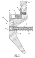
- Figure 2 shows in cross-sectional view a first embodiment of a tool according to the invention in a first position.
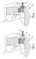
- Figures 3 and 4 show the device according to figure 2 in two different positions.
- Figures 5 and 6 show a second embodiment of a tool according to the invention in two different positions.
- Figure 7 shows a third embodiment of a tool according to the invention.
- Figure 8 shows a fourth embodiment in cross-sectional view.
- Figure 9 shows a fifth embodiment of the invention in cross-sectional view.
- Figure 1 shows a tool 1 with a receiving end 2. This receiving end 2 is inserted into a receiving structure 3 which will hold the tool 1.
- a safety member 4 is provided which protrudes out of the tool 1 and engages with a cavity 5 in the receiving structure 3. This prevents the tool 1 from falling out of the receiving structure 3 when the clamping force is released. Only after actuating the safety member 4 such that it is retracted into the receiving end 2, the tool 1 can be removed from the receiving structure 3.
- Figure 2 shows in partial cross-sectional view a first embodiment of a tool 10 according to the invention.
- This tool 10 has also a receiving end 2 and a safety member 4 which can be inserted into the receiving structure 3 and engages with the cavity 5.
- the tool 10 is furthermore provided with actuating and energizing means comprising a spring 11, which can be compressed by a pusher 12.
- actuating and energizing means comprising a spring 11, which can be compressed by a pusher 12.
- the bottom part of the spring 11 is maintained in position by a cam 13, which is connected to a piezo element 14.
- the pusher 12 On insertion of the tool 10 into the receiving structure 3 (see figure 3) the pusher 12 is moved into the receiving end 2 of the tool 10, thereby compressing the spring 11 and storing energy.
- the spring energy of the spring 11 is stored to be used for actuating the safety member 4 at a later stage.
- the tool 10 is released from the receiving structure 3.
- the piezo element 14 is activated by an electric current, such that the cam 13 is retracted and the spring energy of the spring 11 is released.
- the spring energy drives a wedge 15 downwards, which coacts with a wedge surface 16 of the safety member 4.
- the spring 11 now retracts the safety member 4 into the receiving end 2 of the tool 10 enabling removal of the tool 10 from the receiving structure 3.
- the pusher 12 will be able to move up making the spring 11 tension free.
- the spring 17 acting directly on the safety member 4 will after removal of the tool 10 from the receiving structure 3 push the safety member 4 outward again, driving the wedge 15 upward and by deactivating the piezo element 14 the tool 10 is brought into its original state as shown in figure 2.
- the safety member could also be embodied as a rotatable safety member, which is moved from a tool locking position to a tool releasing position by rotating the safety member, instead of shifting the safety member.
- Figures 5 and 6 show a second embodiment of a tool 20 according to the invention.
- Figure 5 shows the safety member 4 in a tool locking position
- figure 6 shows the safety member 4 in a tool releasing position.
- the tool 20 is provided with a cylinder 21 in which piston 22 is arranged.
- This piston 22 is connected to the safety member 4.
- the piston 22 is provided with an opening 23 connecting to the cylinder 21.
- FIG. 7 shows a third embodiment of a tool 30 according to the invention.
- This tool 30 has a cylinder 31 in which part of the safety member 4 acts as a piston 32.
- the tool 30 has in its body 36 connecting means 37 with which the tool 30 can be grabbed and held.
- a rod 33 can be screwed into this connecting means 37 in order to grab and hold the tool 30.
- the rod 33 is provided with a channel 34, which connects to a channel 35, which in turn is in connection with the cylinder 31.
- the piston 32 is actuated bringing the safety member 4 from a tool locking position to a tool releasing position.
- Figure 8 shows a fourth embodiment of a tool 40 according to the invention.
- the tool 40 again has a safety member 4.
- the tool is furthermore provided with an electric motor 41, which drives a screw spindle 42, which screw spindle 42 connects to the safety member 4.
- the safety member 4 can be moved between the tool locking position and the tool releasing position.
- FIG 9 shows a fifth embodiment of a tool 50 according to the invention.
- This tool 50 has in its receiving end 2 an electromagnet 51, which drives a wedge-shaped element 52.
- This wedge-shaped element engages with an oblique surface 53 present on the safety member 4.
- the safety member protrudes from a side surface of the receiving end of the tool.
- the safety member could also be arranged on top of the tool or any other part of the tool, while being able to be actuated according to the invention.
- safety member could also be provided with a push button for manual operation of the safety member in combination with the invention.
Landscapes
- Engineering & Computer Science (AREA)
- Mechanical Engineering (AREA)
- Portable Nailing Machines And Staplers (AREA)
- Snaps, Bayonet Connections, Set Pins, And Snap Rings (AREA)
- Auxiliary Devices For Machine Tools (AREA)
- Mechanical Control Devices (AREA)
- Manipulator (AREA)
- Drilling And Boring (AREA)
- Finish Polishing, Edge Sharpening, And Grinding By Specific Grinding Devices (AREA)
- Preventing Unauthorised Actuation Of Valves (AREA)
Abstract
- a safety device for preventing the tool from accidentally falling out of the receiving structure, which safety device has a tool releasing position and a tool locking position;
- energizable actuating means for actuating the safety device; and
- energizing means for energizing the actuating means,
and to a method for exchanging such tool from a receiving structure.
Description
- The invention relates to an exchangeable tool for holding in a receiving structure, the tool comprising:
- a safety device for preventing the tool from accidentally falling out of the receiving structure, which safety device has a tool releasing position and a tool locking position.
- Such a device is for example known from the
European patent No. 0 494 714 . According to this publication a tool is arranged with a safety member, which protrudes out of the surface of the tool and engages in a cavity of the receiving structure. When the clamping force of the receiving structure is removed, the safety member prevents the tool from falling out. Only after operating a push button the safety member is retracted and the tool can be taken out of the receiving structure, substantially perpendicular to the length of the receiving structure. The claims recite an actuating member, which can be embodied as a push button. The actuating member can however not convert energy into a movement to retract the safety device. - when automating the exchange of tools, a manipulator is used to take the tools out of the receiving structure and to arrange tools in said receiving structure. With the tools according to the prior art having a safety device, this safety device has to be operated in order to be able to remove the tools from the receiving structure, substantially perpendicular to the length of the receiving structure. Accordingly the manipulator has to be equipped with a gripper, which not only grips and holds the tool, but also operates the safety device.
- Several grippers are already known, which mechanically operate the safety device in the same manner as a human operator would do. The disadvantage of such grippers is the low flexibility in handling different types of tools. Such grippers are only able to operate tools in which the push button is arranged at a known position. For example a small tool has only one push button, while a large and long tool generally has at least two push buttons. Such known grippers are only able to operate one of the two types of tools. In order to be able to exchange both types of tools, the robot has to change the gripper to be able to exchange the other tool.
- It is now an object of the invention to provide for an exchangeable tool, which allows for a better flexibility and enable an automatic exchanging system to exchange different types of tools with just one gripper.
- This object of the invention is achieved by an exchangeable tool, which is characterized by actuating means for actuating the safety device; and energizing means for energizing the actuating means. By arranging the actuating means in the exchangeable tool, the gripper of the manipulator no longer needs to have a specific device to actuate for example the push button of a tool. These actuating means are energized by the energizing means, such that the energy is converted to a movement urging the safety device from the tool releasing position towards the tool locking position or from the tool releasing position to the tool locking position to lock the tool in the receiving structure.
- In a preferred embodiment of the tool according to the invention the actuating means comprise an electric motor for driving the safety device from the tool locking position to the tool releasing position in order to remove the tool from the receiving structure or from the tool releasing position to the tool locking position to lock the tool in the receiving structure. With such an embodiment the energizing means supply an electric current to the electric motor. This electric current is easily provided for by for example the gripper of the manipulator or through the receiving structure.
- Preferably the actuating means comprise a screw spindle, driven by the electric motor, which screw spindle is connected to the safety device. This screw spindle enables to convert the rotation of the electric motor into a linear movement, which is advantageous for example in a tool using a push button.
- In another embodiment of the tool according to the invention the actuating means comprise an electromagnet for driving the safety device from the tool locking position to the tool releasing position in order to remove the tool from the receiving structure or from the tool releasing position to the tool locking position to lock the tool in the receiving structure.
- In yet another embodiment of the invention the actuating means comprise a transmission to redirect the driving force of the actuating means under an angle, e.g. perpendicular. Due to the shape of the tool and the receiving structure it is not always possible to arrange the actuating means with their actuating direction in line with the necessary direction of movement of the safety device. By using for example a wedge the direction of the actuating means can be converted to another direction. This enables the actuating means to be arranged at the tool at different locations. Other examples of transmissions are: toothrack-gear transmission, a lever transmission and gear transmission.
- Preferably the energizing means comprise a connector connected to the actuating means for receiving energy and transmitting the energy to the actuating means. The energy can be received from for example the gripper of the robot, which provides the energy after it has grabbed the tool, to have the actuating means bring the safety device in the tool releasing position, such that the manipulator can retract the tool from the receiving structure.
- In another preferred embodiment of the tool according to the invention, the actuating means comprise a pneumatic or hydraulic cylinder connected to the safety device. Hydraulic or pneumatic pressure is generally available with the receiving structure and can also be used to operate the safety device by the actuating means.
- Preferably the energizing means comprise a connector for supplying compressed air or a hydraulic fluid to the cylinder to energize the actuating means. For example the gripper has a pneumatic line, which can be connected to the tool and through which the safety device can be operated. So only after connection of the gripper with the tool the safety device can be operated which increases the safety.
- In yet another preferred embodiment of the tool according to the invention, the energizing means and actuating means comprise spring means. Preferably the spring means are tensioned upon insertion of the tool into the receiving structure to store energy and wherein the spring energy is released to actuate the safety device. When inserting the tool into the receiving structure a force is already applied by the manipulator onto the tool. A portion of this force can be stored into spring means as energy and can be used at a later stage to operate the safety device. The releasing of this spring energy can be controlled by control means for example a mechanical action performed by the gripper or by applying a small electric current to a small electric actuator, such as a piezo element.
- The invention further relates to a method for exchanging a tool from a receiving structure comprising:
- providing an exchangeable tool according to the invention;
- grabbing the exchangeable tool;
- energizing the energizable actuating means by the energizing means to move the safety device to the tool releasing position;
- taking the exchangeable tool from the receiving structure.
- The invention also relates to a method for inserting a tool into a receiving structure comprising:
- providing an exchangable tool according to the invention;
- inserting the tool into the receiving structure substantially perpendicular to the length of the receiving structure;
- energizing the energizable actuating means by the energizing means to move the safety device to the tool locking position.
- It is further preferred that the energizing means provide an electric current or a pressurized fluid or spring energy to energize the energizable actuating means.
- These and other features of the invention will be elucidated with the accompanying drawings.
- Figure 1 shows schematically a tool having a safety device and receiving structure.
- Figure 2 shows in cross-sectional view a first embodiment of a tool according to the invention in a first position.
- Figures 3 and 4 show the device according to figure 2 in two different positions.
- Figures 5 and 6 show a second embodiment of a tool according to the invention in two different positions.
- Figure 7 shows a third embodiment of a tool according to the invention.
- Figure 8 shows a fourth embodiment in cross-sectional view.
- Figure 9 shows a fifth embodiment of the invention in cross-sectional view.
- Figure 1 shows a
tool 1 with a receivingend 2. This receivingend 2 is inserted into a receivingstructure 3 which will hold thetool 1. Asafety member 4 is provided which protrudes out of thetool 1 and engages with acavity 5 in thereceiving structure 3. This prevents thetool 1 from falling out of the receivingstructure 3 when the clamping force is released. Only after actuating thesafety member 4 such that it is retracted into the receivingend 2, thetool 1 can be removed from the receivingstructure 3. - Figure 2 shows in partial cross-sectional view a first embodiment of a
tool 10 according to the invention. Thistool 10 has also a receivingend 2 and asafety member 4 which can be inserted into the receivingstructure 3 and engages with thecavity 5. - The
tool 10 is furthermore provided with actuating and energizing means comprising aspring 11, which can be compressed by apusher 12. The bottom part of thespring 11 is maintained in position by acam 13, which is connected to apiezo element 14. - On insertion of the
tool 10 into the receiving structure 3 (see figure 3) thepusher 12 is moved into the receivingend 2 of thetool 10, thereby compressing thespring 11 and storing energy. The spring energy of thespring 11 is stored to be used for actuating thesafety member 4 at a later stage. - In figure 4 the
tool 10 is released from the receivingstructure 3. First of all the clamping force of the receivingstructure 3 is removed and then thepiezo element 14 is activated by an electric current, such that thecam 13 is retracted and the spring energy of thespring 11 is released. The spring energy drives awedge 15 downwards, which coacts with awedge surface 16 of thesafety member 4. Thespring 11 now retracts thesafety member 4 into the receivingend 2 of thetool 10 enabling removal of thetool 10 from the receivingstructure 3. When removing thetool 10 from the receivingstructure 3 thepusher 12 will be able to move up making thespring 11 tension free. Thespring 17 acting directly on thesafety member 4, will after removal of thetool 10 from the receivingstructure 3 push thesafety member 4 outward again, driving thewedge 15 upward and by deactivating thepiezo element 14 thetool 10 is brought into its original state as shown in figure 2. - The safety member could also be embodied as a rotatable safety member, which is moved from a tool locking position to a tool releasing position by rotating the safety member, instead of shifting the safety member.
- Figures 5 and 6 show a second embodiment of a
tool 20 according to the invention. Figure 5 shows thesafety member 4 in a tool locking position, while figure 6 shows thesafety member 4 in a tool releasing position. - The
tool 20 is provided with acylinder 21 in whichpiston 22 is arranged. Thispiston 22 is connected to thesafety member 4. Thepiston 22 is provided with anopening 23 connecting to thecylinder 21. - Now when the
tool 20 has to be removed from the receiving structure 3 atube 24 is inserted into the opening 23 (see figure 6). After insertion of thetube 24 compressed air is supplied to thecylinder 21 pushing thepiston 22 and bringing thesafety member 4 from the tool locking position to the tool releasing position. - Figure 7 shows a third embodiment of a
tool 30 according to the invention. Thistool 30 has acylinder 31 in which part of thesafety member 4 acts as apiston 32. Thetool 30 has in itsbody 36 connectingmeans 37 with which thetool 30 can be grabbed and held. For example arod 33 can be screwed into this connecting means 37 in order to grab and hold thetool 30. Therod 33 is provided with achannel 34, which connects to achannel 35, which in turn is in connection with thecylinder 31. Again by providing compressed air or a hydraulic fluid thepiston 32 is actuated bringing thesafety member 4 from a tool locking position to a tool releasing position. - It is also possible to have a heat expandable polymer in the
cylinder 31. By expanding the polymer inchannel 35 the safety member can be activated. It is possible to expand the polymer using, for instance, heat or an electric current. - Figure 8 shows a fourth embodiment of a
tool 40 according to the invention. Thetool 40 again has asafety member 4. The tool is furthermore provided with anelectric motor 41, which drives ascrew spindle 42, which screwspindle 42 connects to thesafety member 4. By driving themotor 41 thesafety member 4 can be moved between the tool locking position and the tool releasing position. - Figure 9 shows a fifth embodiment of a
tool 50 according to the invention. Thistool 50 has in its receivingend 2 anelectromagnet 51, which drives a wedge-shapedelement 52. This wedge-shaped element engages with anoblique surface 53 present on thesafety member 4. - When the
electromagnet 51 is actuated the wedge-shaped element is pushed outward and engages theoblique surface 53. This wedge transmission converts the vertical movement of theelectromagnet 51 into a horizontal movement bringing thesafety member 4 from the tool locking position towards the tool releasing position. - In the embodiments shown, the safety member protrudes from a side surface of the receiving end of the tool. The safety member could also be arranged on top of the tool or any other part of the tool, while being able to be actuated according to the invention.
- Furthermore the safety member could also be provided with a push button for manual operation of the safety member in combination with the invention.
Claims (17)
- Exchangeable tool for holding in a receiving structure, the tool comprising:- a safety device for preventing the tool from accidentally falling out of the receiving structure, which safety device has a tool releasing position and a tool locking position;characterized by- energizable actuating means for actuating the safety device; and- energizing means for energizing the actuating means.
- Tool according to claim 1, wherein the actuating means comprise an electric motor for driving the safety device from the tool locking position to the tool releasing position in order to remove the tool from the receiving structure or from the tool releasing position to the tool locking position to lock the tool in the receiving structure.
- Tool according to claim 2, wherein the actuating means comprise a screw spindle, driven by the electric motor, which screw spindle is connected to the safety device.
- Tool according to claim 1, wherein the actuating means comprise an electromagnet for driving the safety device from the tool locking position to the tool releasing position in order to remove the tool from the receiving structure, or from the tool releasing position to the tool locking position to lock the tool in the receiving structure.
- Tool according to claim 1, wherein the actuating means comprise an expandable polymer for driving the safety device from the tool locking position to the tool releasing position in order to remove the tool from the receiving structure, or from the tool releasing position to the tool locking position to lock the tool in the receiving structure.
- Tool according to claim 1, wherein the actuating means comprise a mechanism for driving the safety device from the tool locking position to the tool releasing position in order to remove the tool from the receiving structure, or from the tool releasing position to the tool locking position to lock the tool in the receiving structure.
- Tool according to any of the claims 2 - 6, wherein the actuating means comprise a transmission to redirect the driving force of the actuating means under an angle, e.g. perpendicular.
- Tool according to any of the claims 2-6, wherein the energizing means comprise a connector connected to the actuating means for receiving energy and transmitting the energy to the actuating means.
- Tool according to claim 1, wherein the actuating means comprise a pneumatic or hydraulic cylinder connected to the safety device.
- Tool according to claim 9, wherein the energizing means comprise a connector for supplying compressed air or a hydraulic fluid to the cylinder to energize the actuating means.
- Tool according to any of the preceding claims, wherein the energizing means and actuating means comprise spring means.
- Tool according to claim 11, wherein the spring means are tensioned upon insertion of the tool into the receiving structure to store energy and wherein the spring energy is released to actuate the safety device.
- Tool according to claim 11 or 12, comprising control means to control the release of spring energy upon application of a control signal.
- Tool according to claim 13, wherein the control means comprise a piezo electric element for moving a cam to release the tensioned spring means.
- A method for exchanging a tool from a receiving structure comprising:- providing an exchangeable tool according to any of the preceding claims;- grabbing the exchangeable tool;- energizing the energizable actuating means by the energizing means to move the safety device to the tool releasing position;- taking the exchangeable tool from the receiving structure.
- A method for inserting a tool into a receiving structure comprising:- providing an exchangable tool according to any of the preceding claims 13-14;- inserting the tool into the receiving structure;- energizing the energizable actuating means by the energizing means to move the safety device to the tool locking position.
- The method according to claim 15 or 16, wherein the energizing means provide an electric current or a pressurized fluid or spring energy to energize the energizable actuating means.
Priority Applications (9)
| Application Number | Priority Date | Filing Date | Title |
|---|---|---|---|
| DE602006019950T DE602006019950D1 (en) | 2006-06-01 | 2006-06-01 | Tool with automatic locking |
| PL06011423T PL1862233T3 (en) | 2006-06-01 | 2006-06-01 | Tool with an automatic safety click |
| AT06011423T ATE497415T1 (en) | 2006-06-01 | 2006-06-01 | AUTOMATIC LOCKING TOOL |
| ES06011423T ES2356911T3 (en) | 2006-06-01 | 2006-06-01 | TOOL WITH AN AUTOMATIC SECURITY DEVICE. |
| EP06011423A EP1862233B1 (en) | 2006-06-01 | 2006-06-01 | Tool with an automatic safety click |
| US11/807,761 US8099992B2 (en) | 2006-06-01 | 2007-05-30 | Automatic safety click |
| JP2007145425A JP5734542B2 (en) | 2006-06-01 | 2007-05-31 | Automatic safety nails |
| CN2007101292401A CN101085505B (en) | 2006-06-01 | 2007-06-01 | Automatic safety click |
| JP2013159004A JP6005602B2 (en) | 2006-06-01 | 2013-07-31 | Automatic safety nails |
Applications Claiming Priority (1)
| Application Number | Priority Date | Filing Date | Title |
|---|---|---|---|
| EP06011423A EP1862233B1 (en) | 2006-06-01 | 2006-06-01 | Tool with an automatic safety click |
Publications (2)
| Publication Number | Publication Date |
|---|---|
| EP1862233A1 true EP1862233A1 (en) | 2007-12-05 |
| EP1862233B1 EP1862233B1 (en) | 2011-02-02 |
Family
ID=37056932
Family Applications (1)
| Application Number | Title | Priority Date | Filing Date |
|---|---|---|---|
| EP06011423A Active EP1862233B1 (en) | 2006-06-01 | 2006-06-01 | Tool with an automatic safety click |
Country Status (8)
| Country | Link |
|---|---|
| US (1) | US8099992B2 (en) |
| EP (1) | EP1862233B1 (en) |
| JP (2) | JP5734542B2 (en) |
| CN (1) | CN101085505B (en) |
| AT (1) | ATE497415T1 (en) |
| DE (1) | DE602006019950D1 (en) |
| ES (1) | ES2356911T3 (en) |
| PL (1) | PL1862233T3 (en) |
Cited By (3)
| Publication number | Priority date | Publication date | Assignee | Title |
|---|---|---|---|---|
| EP2314394A3 (en) * | 2009-10-19 | 2014-01-22 | TRUMPF Maschinen Austria GmbH & Co. KG. | Bending tool, in particular with offset cross-section |
| WO2014201489A1 (en) * | 2013-06-20 | 2014-12-24 | Trumpf Maschinen Austria Gmbh & Co. Kg. | Bending tool |
| WO2018057913A1 (en) * | 2016-09-23 | 2018-03-29 | Mate Precision Tooling, Inc. | Press brake tool safety latch mechanism |
Families Citing this family (19)
| Publication number | Priority date | Publication date | Assignee | Title |
|---|---|---|---|---|
| DE102006001677B3 (en) * | 2006-01-12 | 2007-05-03 | Gebr. Brasseler Gmbh & Co. Kg | Surgical connection device e.g. for removable connection of hand piece to surgical instrument, has recess in which coupling part of instrument can be inserted and at wall on inside of recess resting recess is provided |
| PL1980337T3 (en) * | 2007-04-13 | 2013-01-31 | Wila Bv | Clamping device for bending tools |
| JP5833927B2 (en) * | 2008-11-11 | 2015-12-16 | ウィラ・ベスローテン・フェンノートシャップWila B.V. | Device for clamping tools |
| GB2481420B (en) * | 2010-06-23 | 2012-06-13 | Rolls Royce Plc | Press brake |
| JP5622456B2 (en) * | 2010-06-28 | 2014-11-12 | オリイメック株式会社 | Hand attachment / detachment mechanism in workpiece transfer device |
| US8443646B2 (en) | 2011-04-19 | 2013-05-21 | Bruno J. Pelech | Compensation device for a press brake |
| JP5947620B2 (en) * | 2012-05-23 | 2016-07-06 | 株式会社アマダホールディングス | Upper mold and upper mold temporary fixing method |
| ITPC20130024A1 (en) * | 2013-09-13 | 2015-03-14 | Rolleri S P A | DEVICE FOR LOCKING TOOLS IN A FOLDING PRESS |
| DE102016002765B3 (en) * | 2016-03-05 | 2017-06-22 | Audi Ag | Device with press, tool and tool protection system for the processing of sheet metal workpieces and adjustable distance means usable therefor |
| CN106514685B (en) * | 2017-01-11 | 2018-09-25 | 中国科学院合肥物质科学研究院 | A kind of robot quick change finger structure |
| CN106678150B (en) * | 2017-02-24 | 2019-06-04 | 东风汽车公司 | Fast self-locking fixing device and its working method |
| US10792716B2 (en) * | 2017-06-29 | 2020-10-06 | Mate Precision Tooling, Inc. | Magnetic press brake and machine tooling engagement systems |
| WO2019176808A1 (en) * | 2018-03-14 | 2019-09-19 | 日本電産株式会社 | Robot hand and robot |
| IT201900006656A1 (en) | 2019-05-08 | 2020-11-08 | Salvagnini Italia Spa | Bending machine for metal sheets |
| CN112655574A (en) * | 2020-12-25 | 2021-04-16 | 青海裕福畜牧业发展有限公司 | Sow obstetric table for live pig breeding and use method thereof |
| US12246369B2 (en) | 2021-05-13 | 2025-03-11 | Accurpress America Inc. | Press brake safety latch |
| JP2023036277A (en) * | 2021-09-02 | 2023-03-14 | オムロン株式会社 | Robot, robot control method, and program |
| EP4186833A1 (en) * | 2021-09-28 | 2023-05-31 | Unilogo Robotics Spolka Z Ograniczona Odpowiedzialnoscia | A handle for a production line transport trolley, a method of retooling the handle according to the invention, a set of handles according to the invention and a method of transporting product using at least two sets of handles according to the invention |
| EP4180140A1 (en) * | 2021-11-16 | 2023-05-17 | Bystronic Laser AG | Bending machine |
Citations (3)
| Publication number | Priority date | Publication date | Assignee | Title |
|---|---|---|---|---|
| EP0494714A1 (en) * | 1991-01-10 | 1992-07-15 | Machinefabriek Wila B.V. | Press tool and an adaptor and a press therefor |
| WO2004024361A1 (en) * | 2002-09-16 | 2004-03-25 | Trumpf Maschinen Austria Gmbh & Co. Kg. | Bending tool and tool holding fixture therefor |
| EP1698408A1 (en) * | 2003-07-01 | 2006-09-06 | Wilson Tool International, Inc. | Press brake tool having lockable safety key |
Family Cites Families (45)
| Publication number | Priority date | Publication date | Assignee | Title |
|---|---|---|---|---|
| US1425727A (en) * | 1921-06-27 | 1922-08-15 | Lane Mfg Company | Truck |
| US1708854A (en) * | 1927-11-11 | 1929-04-09 | Gen Electric | Means for handling sheet steel |
| US2468055A (en) * | 1945-11-28 | 1949-04-26 | John W Gibler | Load-dumping pallet |
| US2570726A (en) * | 1948-10-19 | 1951-10-09 | Hyster Co | Conveyance loading apparatus |
| US2812080A (en) * | 1956-02-06 | 1957-11-05 | Jose M Campos | Vehicle beds |
| US4355940A (en) * | 1980-05-21 | 1982-10-26 | Derickson Edward E | Automatic loading platform and method of using same |
| JPS6347023U (en) * | 1986-09-16 | 1988-03-30 | ||
| JPS63260627A (en) * | 1988-03-18 | 1988-10-27 | ヘンメルレ・アー・ゲー・マシネンフアブリツク | Tool fixing device for press brake |
| JP2620707B2 (en) * | 1988-08-04 | 1997-06-18 | 武 林 | Lift-spoke type cargo handling equipment |
| NL8802402A (en) * | 1988-09-29 | 1990-04-17 | Wila Maschf Bv | CLAMP DEVICE, EG. FOR THE UPPER TOOL OF A PRESS BRAKE. |
| DD277641A1 (en) | 1988-12-08 | 1990-04-11 | Warnke Umformtech Veb K | TOOL CHANGERS FOR THE AUTOMATIC TRANSPORT OF INTERCHANGEABLE TOOLS OR TOOL TRADE RECEIVERS AT PRESSES |
| NL8901560A (en) * | 1989-06-21 | 1991-01-16 | Wila Maschf Bv | PRESS BUTTON AND AN AUTOMATIC BOMB DEVICE THEREFOR. |
| US5009098A (en) * | 1989-11-27 | 1991-04-23 | Machinefabriek Wila B.V. | Press and curve-forming means therefor |
| JPH04319097A (en) * | 1991-04-17 | 1992-11-10 | Fuji Electric Co Ltd | Clamping device for press machine |
| JPH06115891A (en) | 1991-12-04 | 1994-04-26 | Eizo Aoki | Device for scraping up cargo intended to be conveyed |
| JP2527640Y2 (en) * | 1992-08-26 | 1997-03-05 | 川崎重工業株式会社 | Industrial robot tool changer |
| DE4321314C2 (en) | 1993-06-26 | 1995-06-01 | Packautomatic Gmbh & Co Kg | Device for loading and / or unloading containers |
| JP3841911B2 (en) * | 1997-03-07 | 2006-11-08 | 株式会社アマダ | Upper mold in press |
| JPH10263971A (en) * | 1997-03-25 | 1998-10-06 | Brother Ind Ltd | Machine tool tool changer |
| US6003360A (en) * | 1997-07-01 | 1999-12-21 | Wilson Tool International, Inc. | Press brake tool holder |
| FR2781174B1 (en) | 1998-07-20 | 2000-10-06 | Essilor Int | FINISHING TOOL, PARTICULARLY FOR OPHTHALMIC LENS, AND EQUIPMENT SPECIFIC TO ITS IMPLEMENTATION |
| US6264417B1 (en) * | 1999-04-21 | 2001-07-24 | Eastman Kodak Company | Flexible roll chucking assemblage and method |
| US6267116B1 (en) * | 1999-07-06 | 2001-07-31 | The Rxfiles Corporation | Method and system for use in treating a patient with any drug to optimize therapy and prevent an adverse drug |
| US6581607B2 (en) * | 1999-07-06 | 2003-06-24 | The Rx Files Corporation | Method and system for use in treating a patient with a biological substance to optimize therapy and prevent an adverse response |
| US6581606B2 (en) * | 1999-07-06 | 2003-06-24 | The Rx Files Corporation | Method, apparatus and system for use in treating patient with a drug having an antineoplastic effect to optimize therapy and prevent an adverse drug response |
| US6575169B2 (en) * | 1999-07-06 | 2003-06-10 | The Rxfiles Corporation | Method and apparatus for use in treating a patient with any drug to optimize therapy and prevent an adverse drug |
| IT1311880B1 (en) * | 1999-11-30 | 2002-03-19 | Luciano Gasparini | SUPPORT AND LOCKING DEVICE WITH SAFETY FUNCTION AT LEAST ONE INTERCHANGEABLE TOOL, PARTICULARLY IN A MACHINE |
| NL1014147C2 (en) | 2000-01-21 | 2001-07-24 | Sjoerd Meijer | Carriage for transporting goods, e.g. loading pallets onto lorries, moves goods on two sets of rollers cooperating with each other |
| US6516649B1 (en) * | 2000-09-13 | 2003-02-11 | Wilson Tool International, Inc. | Press brake tooling providing stabilization between die and die holder |
| US6327884B1 (en) * | 2000-09-29 | 2001-12-11 | Wilson Tool International, Inc. | Press brake tooling with hardened surfaces |
| US6557390B2 (en) * | 2001-05-11 | 2003-05-06 | Wilson Tool International, Inc. | Press brake assemblies, tool holder apparatuses, and components thereof |
| US6564611B2 (en) * | 2001-07-30 | 2003-05-20 | Wilson Tool International, Inc. | Hydraulic press brake tool holder |
| US6467327B1 (en) * | 2001-08-15 | 2002-10-22 | Wilson Tool International, Inc. | Press brake tool and tool holder |
| JP4090754B2 (en) * | 2002-02-12 | 2008-05-28 | 株式会社アマダ | Mold changer |
| AUPS312302A0 (en) * | 2002-06-19 | 2002-07-18 | Telezygology Inc | Further improvements in fixing and release systems |
| FR2844213B1 (en) * | 2002-09-09 | 2004-11-26 | Amada Europ Sa | COMB SYSTEM FOR INTERMEDIATES |
| PT102913A (en) * | 2003-02-17 | 2004-08-31 | Dias Ramos Maquinas Ferramenta | REVERSIBLE AND FAST TIGHTENING OF GRINDING TOOLS |
| US6928852B2 (en) * | 2003-03-31 | 2005-08-16 | Wila B.V. | Combination of a press brake clamping system and at least a press brake tool |
| US7021116B2 (en) * | 2003-12-19 | 2006-04-04 | Wilson Tool International, Inc. | Press brake tooling technology |
| US6848291B1 (en) * | 2004-02-13 | 2005-02-01 | Wilson Tool International, Inc. | Press brake tool and tool holder |
| US7721586B2 (en) * | 2005-02-08 | 2010-05-25 | Wilson Tool International Inc. | Press brake tool seating technology |
| US7308817B2 (en) * | 2005-02-08 | 2007-12-18 | Wilson Tool International Inc. | Push plate tool holder for press brakes |
| DE202005010693U1 (en) | 2005-07-07 | 2005-09-15 | Keppler Karl | Tool changing assembly for HSK tool has two raised ridges at right angles engaging with matching grooves |
| EP1862255B1 (en) * | 2006-06-01 | 2011-03-16 | Wila B.V. | Combination of an exchangeable tool and a manipulator |
| US7634935B2 (en) * | 2006-10-05 | 2009-12-22 | Rolleri S.P.A. | Quick upper tool coupling and uncoupling device of a press brake |
-
2006
- 2006-06-01 PL PL06011423T patent/PL1862233T3/en unknown
- 2006-06-01 DE DE602006019950T patent/DE602006019950D1/en active Active
- 2006-06-01 ES ES06011423T patent/ES2356911T3/en active Active
- 2006-06-01 EP EP06011423A patent/EP1862233B1/en active Active
- 2006-06-01 AT AT06011423T patent/ATE497415T1/en active
-
2007
- 2007-05-30 US US11/807,761 patent/US8099992B2/en active Active
- 2007-05-31 JP JP2007145425A patent/JP5734542B2/en active Active
- 2007-06-01 CN CN2007101292401A patent/CN101085505B/en active Active
-
2013
- 2013-07-31 JP JP2013159004A patent/JP6005602B2/en active Active
Patent Citations (3)
| Publication number | Priority date | Publication date | Assignee | Title |
|---|---|---|---|---|
| EP0494714A1 (en) * | 1991-01-10 | 1992-07-15 | Machinefabriek Wila B.V. | Press tool and an adaptor and a press therefor |
| WO2004024361A1 (en) * | 2002-09-16 | 2004-03-25 | Trumpf Maschinen Austria Gmbh & Co. Kg. | Bending tool and tool holding fixture therefor |
| EP1698408A1 (en) * | 2003-07-01 | 2006-09-06 | Wilson Tool International, Inc. | Press brake tool having lockable safety key |
Cited By (5)
| Publication number | Priority date | Publication date | Assignee | Title |
|---|---|---|---|---|
| EP2314394A3 (en) * | 2009-10-19 | 2014-01-22 | TRUMPF Maschinen Austria GmbH & Co. KG. | Bending tool, in particular with offset cross-section |
| WO2014201489A1 (en) * | 2013-06-20 | 2014-12-24 | Trumpf Maschinen Austria Gmbh & Co. Kg. | Bending tool |
| US10144045B2 (en) | 2013-06-20 | 2018-12-04 | Trumpf Maschinen Austria Gmbh & Co. Kg. | Bending tool |
| WO2018057913A1 (en) * | 2016-09-23 | 2018-03-29 | Mate Precision Tooling, Inc. | Press brake tool safety latch mechanism |
| US9962749B2 (en) | 2016-09-23 | 2018-05-08 | Mate Precision Tooling, Inc. | Press brake tool safety latch mechanism |
Also Published As
| Publication number | Publication date |
|---|---|
| JP6005602B2 (en) | 2016-10-12 |
| CN101085505A (en) | 2007-12-12 |
| CN101085505B (en) | 2012-05-30 |
| JP5734542B2 (en) | 2015-06-17 |
| JP2008020062A (en) | 2008-01-31 |
| JP2014025586A (en) | 2014-02-06 |
| US20080040864A1 (en) | 2008-02-21 |
| ES2356911T3 (en) | 2011-04-14 |
| ATE497415T1 (en) | 2011-02-15 |
| US8099992B2 (en) | 2012-01-24 |
| DE602006019950D1 (en) | 2011-03-17 |
| PL1862233T3 (en) | 2011-07-29 |
| EP1862233B1 (en) | 2011-02-02 |
Similar Documents
| Publication | Publication Date | Title |
|---|---|---|
| US8099992B2 (en) | Automatic safety click | |
| EP2364228B1 (en) | Device for clamping a tool | |
| EP2313236B1 (en) | Tool head assemblies for pressing devices | |
| JP5156350B2 (en) | Hand-held driving device for fixed elements | |
| KR101922590B1 (en) | Clamp apparatus | |
| JP2007326211A (en) | Replaceable tool | |
| CN113752292B (en) | Clamping device | |
| EP0282136A2 (en) | Gripping device | |
| CN115485174A (en) | Electromechanical braking system and method for releasing the electromechanical braking system | |
| WO2004024365A1 (en) | Pipe flaring tool | |
| CN111140561A (en) | Hydraulic pump-valve units for presses | |
| CN113814935B (en) | Press with safety element | |
| CN1821484B (en) | Cable ball joint forming apparatus and method of forming a ball joint in a cable screw | |
| EP2484459A1 (en) | Clamping method and device for carrying out the same | |
| AU2021240803B2 (en) | Self-propelled valve actuator on a rail transport system for manifolds and subsea trees | |
| JPH071203A (en) | Bar loader | |
| EP3260246B1 (en) | Tool coupling | |
| JPS6140515B2 (en) | ||
| CN115674238B (en) | Mechanical arm with stable grabbing performance | |
| HK40074207A (en) | Installation device for carrying out installation steps on a wall and method for exchanging a tool of an installation apparatus | |
| RO111346B1 (en) | Mechanic self-blocking hand |
Legal Events
| Date | Code | Title | Description |
|---|---|---|---|
| PUAI | Public reference made under article 153(3) epc to a published international application that has entered the european phase |
Free format text: ORIGINAL CODE: 0009012 |
|
| AK | Designated contracting states |
Kind code of ref document: A1 Designated state(s): AT BE BG CH CY CZ DE DK EE ES FI FR GB GR HU IE IS IT LI LT LU LV MC NL PL PT RO SE SI SK TR |
|
| AX | Request for extension of the european patent |
Extension state: AL BA HR MK YU |
|
| 17P | Request for examination filed |
Effective date: 20080603 |
|
| 17Q | First examination report despatched |
Effective date: 20080708 |
|
| AKX | Designation fees paid |
Designated state(s): AT BE BG CH CY CZ DE DK EE ES FI FR GB GR HU IE IS IT LI LT LU LV MC NL PL PT RO SE SI SK TR |
|
| GRAP | Despatch of communication of intention to grant a patent |
Free format text: ORIGINAL CODE: EPIDOSNIGR1 |
|
| GRAS | Grant fee paid |
Free format text: ORIGINAL CODE: EPIDOSNIGR3 |
|
| GRAA | (expected) grant |
Free format text: ORIGINAL CODE: 0009210 |
|
| AK | Designated contracting states |
Kind code of ref document: B1 Designated state(s): AT BE BG CH CY CZ DE DK EE ES FI FR GB GR HU IE IS IT LI LT LU LV MC NL PL PT RO SE SI SK TR |
|
| REG | Reference to a national code |
Ref country code: GB Ref legal event code: FG4D |
|
| REG | Reference to a national code |
Ref country code: CH Ref legal event code: EP |
|
| REG | Reference to a national code |
Ref country code: IE Ref legal event code: FG4D |
|
| REF | Corresponds to: |
Ref document number: 602006019950 Country of ref document: DE Date of ref document: 20110317 Kind code of ref document: P |
|
| REG | Reference to a national code |
Ref country code: DE Ref legal event code: R096 Ref document number: 602006019950 Country of ref document: DE Effective date: 20110317 |
|
| REG | Reference to a national code |
Ref country code: ES Ref legal event code: FG2A Ref document number: 2356911 Country of ref document: ES Kind code of ref document: T3 Effective date: 20110414 |
|
| REG | Reference to a national code |
Ref country code: NL Ref legal event code: T3 |
|
| LTIE | Lt: invalidation of european patent or patent extension |
Effective date: 20110202 |
|
| PG25 | Lapsed in a contracting state [announced via postgrant information from national office to epo] |
Ref country code: LV Free format text: LAPSE BECAUSE OF FAILURE TO SUBMIT A TRANSLATION OF THE DESCRIPTION OR TO PAY THE FEE WITHIN THE PRESCRIBED TIME-LIMIT Effective date: 20110202 Ref country code: GR Free format text: LAPSE BECAUSE OF FAILURE TO SUBMIT A TRANSLATION OF THE DESCRIPTION OR TO PAY THE FEE WITHIN THE PRESCRIBED TIME-LIMIT Effective date: 20110503 Ref country code: SE Free format text: LAPSE BECAUSE OF FAILURE TO SUBMIT A TRANSLATION OF THE DESCRIPTION OR TO PAY THE FEE WITHIN THE PRESCRIBED TIME-LIMIT Effective date: 20110202 Ref country code: LT Free format text: LAPSE BECAUSE OF FAILURE TO SUBMIT A TRANSLATION OF THE DESCRIPTION OR TO PAY THE FEE WITHIN THE PRESCRIBED TIME-LIMIT Effective date: 20110202 Ref country code: PT Free format text: LAPSE BECAUSE OF FAILURE TO SUBMIT A TRANSLATION OF THE DESCRIPTION OR TO PAY THE FEE WITHIN THE PRESCRIBED TIME-LIMIT Effective date: 20110602 |
|
| REG | Reference to a national code |
Ref country code: PL Ref legal event code: T3 |
|
| PG25 | Lapsed in a contracting state [announced via postgrant information from national office to epo] |
Ref country code: SI Free format text: LAPSE BECAUSE OF FAILURE TO SUBMIT A TRANSLATION OF THE DESCRIPTION OR TO PAY THE FEE WITHIN THE PRESCRIBED TIME-LIMIT Effective date: 20110202 Ref country code: CY Free format text: LAPSE BECAUSE OF FAILURE TO SUBMIT A TRANSLATION OF THE DESCRIPTION OR TO PAY THE FEE WITHIN THE PRESCRIBED TIME-LIMIT Effective date: 20110202 Ref country code: BG Free format text: LAPSE BECAUSE OF FAILURE TO SUBMIT A TRANSLATION OF THE DESCRIPTION OR TO PAY THE FEE WITHIN THE PRESCRIBED TIME-LIMIT Effective date: 20110502 Ref country code: FI Free format text: LAPSE BECAUSE OF FAILURE TO SUBMIT A TRANSLATION OF THE DESCRIPTION OR TO PAY THE FEE WITHIN THE PRESCRIBED TIME-LIMIT Effective date: 20110202 |
|
| PG25 | Lapsed in a contracting state [announced via postgrant information from national office to epo] |
Ref country code: EE Free format text: LAPSE BECAUSE OF FAILURE TO SUBMIT A TRANSLATION OF THE DESCRIPTION OR TO PAY THE FEE WITHIN THE PRESCRIBED TIME-LIMIT Effective date: 20110202 Ref country code: DK Free format text: LAPSE BECAUSE OF FAILURE TO SUBMIT A TRANSLATION OF THE DESCRIPTION OR TO PAY THE FEE WITHIN THE PRESCRIBED TIME-LIMIT Effective date: 20110202 |
|
| PG25 | Lapsed in a contracting state [announced via postgrant information from national office to epo] |
Ref country code: CZ Free format text: LAPSE BECAUSE OF FAILURE TO SUBMIT A TRANSLATION OF THE DESCRIPTION OR TO PAY THE FEE WITHIN THE PRESCRIBED TIME-LIMIT Effective date: 20110202 Ref country code: RO Free format text: LAPSE BECAUSE OF FAILURE TO SUBMIT A TRANSLATION OF THE DESCRIPTION OR TO PAY THE FEE WITHIN THE PRESCRIBED TIME-LIMIT Effective date: 20110202 Ref country code: SK Free format text: LAPSE BECAUSE OF FAILURE TO SUBMIT A TRANSLATION OF THE DESCRIPTION OR TO PAY THE FEE WITHIN THE PRESCRIBED TIME-LIMIT Effective date: 20110202 |
|
| PLBE | No opposition filed within time limit |
Free format text: ORIGINAL CODE: 0009261 |
|
| STAA | Information on the status of an ep patent application or granted ep patent |
Free format text: STATUS: NO OPPOSITION FILED WITHIN TIME LIMIT |
|
| 26N | No opposition filed |
Effective date: 20111103 |
|
| REG | Reference to a national code |
Ref country code: CH Ref legal event code: PL |
|
| REG | Reference to a national code |
Ref country code: DE Ref legal event code: R097 Ref document number: 602006019950 Country of ref document: DE Effective date: 20111103 |
|
| REG | Reference to a national code |
Ref country code: IE Ref legal event code: MM4A |
|
| PG25 | Lapsed in a contracting state [announced via postgrant information from national office to epo] |
Ref country code: LI Free format text: LAPSE BECAUSE OF NON-PAYMENT OF DUE FEES Effective date: 20110630 Ref country code: IE Free format text: LAPSE BECAUSE OF NON-PAYMENT OF DUE FEES Effective date: 20110601 Ref country code: CH Free format text: LAPSE BECAUSE OF NON-PAYMENT OF DUE FEES Effective date: 20110630 |
|
| PG25 | Lapsed in a contracting state [announced via postgrant information from national office to epo] |
Ref country code: MC Free format text: LAPSE BECAUSE OF NON-PAYMENT OF DUE FEES Effective date: 20110630 |
|
| PG25 | Lapsed in a contracting state [announced via postgrant information from national office to epo] |
Ref country code: LU Free format text: LAPSE BECAUSE OF NON-PAYMENT OF DUE FEES Effective date: 20110601 |
|
| PG25 | Lapsed in a contracting state [announced via postgrant information from national office to epo] |
Ref country code: IS Free format text: LAPSE BECAUSE OF FAILURE TO SUBMIT A TRANSLATION OF THE DESCRIPTION OR TO PAY THE FEE WITHIN THE PRESCRIBED TIME-LIMIT Effective date: 20110202 |
|
| PG25 | Lapsed in a contracting state [announced via postgrant information from national office to epo] |
Ref country code: HU Free format text: LAPSE BECAUSE OF FAILURE TO SUBMIT A TRANSLATION OF THE DESCRIPTION OR TO PAY THE FEE WITHIN THE PRESCRIBED TIME-LIMIT Effective date: 20110202 |
|
| REG | Reference to a national code |
Ref country code: FR Ref legal event code: PLFP Year of fee payment: 11 |
|
| REG | Reference to a national code |
Ref country code: FR Ref legal event code: PLFP Year of fee payment: 12 |
|
| REG | Reference to a national code |
Ref country code: FR Ref legal event code: PLFP Year of fee payment: 13 |
|
| P01 | Opt-out of the competence of the unified patent court (upc) registered |
Effective date: 20230613 |
|
| PGFP | Annual fee paid to national office [announced via postgrant information from national office to epo] |
Ref country code: DE Payment date: 20250627 Year of fee payment: 20 Ref country code: PL Payment date: 20250521 Year of fee payment: 20 |
|
| PGFP | Annual fee paid to national office [announced via postgrant information from national office to epo] |
Ref country code: GB Payment date: 20250627 Year of fee payment: 20 |
|
| PGFP | Annual fee paid to national office [announced via postgrant information from national office to epo] |
Ref country code: NL Payment date: 20250626 Year of fee payment: 20 Ref country code: BE Payment date: 20250627 Year of fee payment: 20 |
|
| PGFP | Annual fee paid to national office [announced via postgrant information from national office to epo] |
Ref country code: FR Payment date: 20250625 Year of fee payment: 20 |
|
| PGFP | Annual fee paid to national office [announced via postgrant information from national office to epo] |
Ref country code: AT Payment date: 20250603 Year of fee payment: 20 |
|
| PGFP | Annual fee paid to national office [announced via postgrant information from national office to epo] |
Ref country code: TR Payment date: 20250526 Year of fee payment: 20 |
|
| PGFP | Annual fee paid to national office [announced via postgrant information from national office to epo] |
Ref country code: ES Payment date: 20250701 Year of fee payment: 20 |
|
| PGFP | Annual fee paid to national office [announced via postgrant information from national office to epo] |
Ref country code: IT Payment date: 20250619 Year of fee payment: 20 |