EP1867961A1 - Air flow rate measuring device and passage - Google Patents
Air flow rate measuring device and passage Download PDFInfo
- Publication number
- EP1867961A1 EP1867961A1 EP07011140A EP07011140A EP1867961A1 EP 1867961 A1 EP1867961 A1 EP 1867961A1 EP 07011140 A EP07011140 A EP 07011140A EP 07011140 A EP07011140 A EP 07011140A EP 1867961 A1 EP1867961 A1 EP 1867961A1
- Authority
- EP
- European Patent Office
- Prior art keywords
- grid
- flow rate
- passage
- rate measuring
- beams
- Prior art date
- Legal status (The legal status is an assumption and is not a legal conclusion. Google has not performed a legal analysis and makes no representation as to the accuracy of the status listed.)
- Granted
Links
Images







Classifications
-
- G—PHYSICS
- G01—MEASURING; TESTING
- G01F—MEASURING VOLUME, VOLUME FLOW, MASS FLOW OR LIQUID LEVEL; METERING BY VOLUME
- G01F1/00—Measuring the volume flow or mass flow of fluid or fluent solid material wherein the fluid passes through a meter in a continuous flow
- G01F1/68—Measuring the volume flow or mass flow of fluid or fluent solid material wherein the fluid passes through a meter in a continuous flow by using thermal effects
- G01F1/684—Structural arrangements; Mounting of elements, e.g. in relation to fluid flow
- G01F1/6842—Structural arrangements; Mounting of elements, e.g. in relation to fluid flow with means for influencing the fluid flow
-
- G—PHYSICS
- G01—MEASURING; TESTING
- G01F—MEASURING VOLUME, VOLUME FLOW, MASS FLOW OR LIQUID LEVEL; METERING BY VOLUME
- G01F15/00—Details of, or accessories for, apparatus of groups G01F1/00 - G01F13/00 insofar as such details or appliances are not adapted to particular types of such apparatus
-
- G—PHYSICS
- G01—MEASURING; TESTING
- G01F—MEASURING VOLUME, VOLUME FLOW, MASS FLOW OR LIQUID LEVEL; METERING BY VOLUME
- G01F15/00—Details of, or accessories for, apparatus of groups G01F1/00 - G01F13/00 insofar as such details or appliances are not adapted to particular types of such apparatus
- G01F15/18—Supports or connecting means for meters
Definitions
- the present invention relates to an air flow rate measuring device, and in particular to an air flow rate measuring device for measuring the air flow which is supplied to an internal combustion engine of an automobile, and a flow rate measuring passage therefor.
- a metal mesh, an aluminum honeycomb or a plastic is used to form a rectifier grid of an air flow rate measuring device.
- the plastic molding in order to maintain the mechanical strength and prevent deformation and deterioration of the grid, is configured to include a first mesh grid having a first thickness and spaces therein and a second rib grid having a thickness larger than the first one and spaces wider than in the first mesh grid, and the first mesh grid and the second rib grid are integrally formed with one another.
- a grid configuration which has a hexagonal second rib grid such as a honeycomb and a first mesh grid between the second rib grid so that the applied radial load can be spread out.
- a deformation of the second rib grid leads to a deformation of the first mesh grid, and also a deformation of the second rib grid at the beginning of the tightening of a hose band or due to the radial load caused by a thermal factor causes a problem of deterioration of the measurement accuracy of the air flow rate measuring device.
- the second rib grid is formed to have a sufficient thickness to maintain the mechanical strength of the rib grid, which results in a large pressure loss across the grid.
- the tightening of a hose band generates two types of radial loads: one type is the load applied due to a configuration factor at the beginning of the tightening of the hose band, and another type is the load caused by a thermal factor, that is the difference in coefficient of linear thermal expansion between the hose band and the body and the rectifier grid due to temperature changes. Therefore, the radial loads due to the two factors generate a stress which causes a deformation of the grid, and the deformation should be taken into the consideration to address the problem which is caused by the radial load at tightening the hose band. In addition, because a resin may exhibit creeps, a deformation of the grid caused by a creep also should be taken into the consideration to address the problem.
- One problem to be solved by the present invention is to provide a flow measuring device or a flow measuring passage having grids which are not easily deformed.
- the above object can be achieved by a flow measuring device in which a grid includes a first grid portion and a second grid portion between the first grid portion and a passage forming component, and the second grid portion is more easily deformed than the first grid portion.
- the present invention can provide an air flow rate measuring device of high performance and high reliability which reduces the pressure loss across the grid due to the load which is generated at the tightening of a hose band, prevents the deterioration of the measurement accuracy of the air flow rate measuring device which is caused by the grid deformation, and enables the grid to have a configuration which results in a smaller pressure loss and high reliability.
- Fig. 1 is a front view of a first embodiment of an air flow rate measuring device according to the present invention, viewed from the upstream side of the air flow.
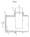
- Fig. 2 is a sectional view taken along the line II-II in Fig. 1.
- Fig. 3 is an enlarged view of the portion A in Fig. 1.
- Fig. 4 is a sectional view showing an example of the layout of an automobile air intake system in which the first embodiment of the air flow rate measuring device according to the present invention is used.
- Fig. 5 is a sectional view taken along the line V-V in Fig. 4.
- Fig. 6 is an enlarged view of the portion A in Fig. 1 and showing the first embodiment of the air flow rate measuring device, before and after a durability test, which is mounted to the air intake system shown in Fig. 4.
- the air flow rate measuring device comprises a body 1 which has a circular cross section and forms a main passage for the intake air flow and a module 2 including a sensing element for sensing the air flow, and the body 1 and the module 2 are fixed to each other by screws 3.
- the screws 3 are used to fix the body 1 and the module 2, but the body 1 and the module 2 may be fixed to each other by welding or adhesive for example other than the screws, to have similar function and effect.
- a rectifier grid 4 is provided inside the body 1 upstream of the module 2 substantially perpendicular to the air flow 8.
- the rectifier grid 4 is arranged close to the upstream duct 12 of the body 1, and the rectifier grid 4 and the body 1 are integrally formed with each other by plastic.
- the rectifier grid 4 comprises a circular frame 5, a mesh grid 6 and a grid 7.
- the circular frame 5 has a shape similar to the cross section of the body 1 and a diameter smaller than that of the inner diameter of the body 1.
- the mesh grid 6 is provided inside the circular frame 5 and is intended to rectify the air flow 8.
- the grid 7 has beams 7-a equiangularly spaced from each other. Each of the beams 7-a is arranged with an angle 7-b relative to a normal line 7-i which extends to the center of the circular frame 5.
- the rectifier grid 4 is formed by integrally forming the circular frame 5, the mesh grid 6, and the grid 7.
- the circular frame 5 having the mesh grid 6 therein is integrally and fixedly supported by the body 1 via both ends of each of the beams 7-a which is disposed between the body 1 and the circular frame 5, that is, via the grid 7. Further, the frame 5 is approximately concentrically disposed within the body 1.
- the duct 12 of the body 1 is inserted into a rubber duct 9, and a metallic hose band 10 is tightened around the rubber duct 9 to fix the rubber duct 9 to the body 1.
- the above configuration causes a radial load 11 from the outer periphery toward the center of the body 1 at the beginning of the tightening of the hose band 10, and the radial load 11 is transferred from the entire outer periphery to the rubber duct 9 and the duct 12 of the body 1.
- another radial load 11 from the outer periphery toward the center of the body 1 is caused due to a thermal factor, that is the difference in the coefficient of linear thermal expansion among the hose band and the body and the rectifier grid due to temperature changes, and transferred from the entire outer periphery to the rubber duct 9 and the duct 12 of the body 1.
- the beams 7-a are provided outside of the frame 5 of the rectifier grid 4 at the angle 7-b with respect to the radial load 11, and therefore the beams 7-a do not become struts against the radial load 11.
- the angle 7-b of the beams 7-a is changed to an angle 7-c due to the radial load 11, which allows the beams 7-a to absorb the radial load 11. This prevents the transfer of the radial load 11 to the mesh grid 6 via the beams 7-a. That is, the grid 7 outside of the frame 5 is configured to be easily deformed by the radial load 11 to a grid shape 7-d so as to enable the grid 7 to absorb the radial load 11.
- the rectifier grid 4 which is configured to absorb the radial load 11 by the deformation of the grid 7 makes it possible to reduce the mechanical strength of the rectifier grid itself.
- the strength required for the mesh grid 6 in the direction of its width 6-a can be reduced.
- the strengths required for the frame 5 and the grid 7 also can be reduced, so that the width 5-a of the frame 5 and the width 7-j of the beams 7-a can be approximately as thin as the width 6-a of the mesh grid 6, and the pressure loss across the rectifier grid 4 can be reduced.
- the mesh grid 6 when the mesh grid 6 needs to have the minimum width 6-a of 0.4 mm for rectifying effect, the mesh grid 6 can have the same minimum width 6-a of 0.4 mm.
- the width 5-a of the frame 5 and the width 7-j of the beams 7-a may be thin within a range from 0.4 mm, which is equal to the minimum width 6-a of the mesh grid 6, to 0.5 mm, which is about 1.25 times that of the minimum width 6-a, and this configuration reduces the pressure loss across the rectifier grid 4 while maintaining the rectifying effect.
- Each of the beams 7-a has a chamfered portion 7-e at the roots of both ends thereof. This relieves concentration of stress at the roots of both ends which is generated when the angle 7-b of the beams 7-a is changed to the angle 7-c.
- the rectifier grid 4 can be molded to have wide apertures at the beams 7-a, which improves its moldability.
- the frame 5 is approximately concentrically disposed within the body 1, but even when the center of the frame 5 is offset from that of the body 1 for example, the device has similar functions and effects, which prevents deterioration of its measurement accuracy, reduces pressure loss, prevents cracks, and improves its moldability while maintaining the rectifying effect.
- the grid 7 since the grid 7 provided outside the frame 5 of the rectifier grid 4 has the beams 7-a which are approximately equiangularly spaced and are inclined in substantially the same direction, the grid 7 can be a substantially regular and uniform grid arrangement.
- the air flow 8 passes through the grid 7, the air flow 8 can be stabilized, and the measurement accuracy of the device can be improved.
- the deformed grid configuration 7-d can be also substantially regular and uniform.
- the air flow 8 passes through the deformed grid 7-d after a certain time duration, the air flow 8 can be still stabilized, and a deterioration of the measurement accuracy of the device can be prevented.
- the frame 5 of the rectifier grid 4 has substantially the same circular cross-sectional shape as the body 1 and is substantially concentrically disposed within the body 1, which enables the tilted grid 7 to have a substantially regular and uniform grid arrangement. And the deformed and tilted grid configuration 7-d due to the radial load 11 after a certain time duration can be also regular and uniform. This achieves an improvement of the measurement accuracy of the device, and prevents a deterioration of the measurement accuracy of the device.
- the deformation of the mesh grid 6 in the rectifier grid 4 due to the radial load 11 at the beginning of tightening of a hose band or the thermal factor and its creep can be prevented, and the width 6-a of the mesh grid 6, the width 5-a of the frame 5, and the width 7-j of the beams 7-a of the rectifier grid 4 can be thinner.
- the tilted configuration of the grid 7 of the rectifier grid 4 can be regular and uniform, and the deformed grid 7-d due to the radial load 11 can have also a regular and uniform grid arrangement.
- the above configuration prevents a deterioration of the measurement accuracy of the air flow rate measuring device, reduces the pressure loss across the device, and also improves the measurement accuracy, and thus provides an air flow rate measuring device of high performance and high reliability.
- Fig. 7 shows a second embodiment of the air flow rate measuring device according to the present invention, and illustrates only the portion corresponding to the portion A in Fig. 1.
- the grid 7 provided outside the frame 5 is configured to have beams 7-a which are arranged at an acute angle 7-b of 45 degrees or less relative to the normal direction 7-i toward the center of the frame 5.
- the effect to absorb the radial load 11 can be enhanced.
- a deterioration of the measurement accuracy of the air flow rate measuring device can be prevented.
- Fig. 8 shows a third embodiment of the air flow rate measuring device according to the present invention, and illustrates only the portion corresponding to the portion A in Fig. 1.
- the grid 7 provided outside the frame 5 is configured to have beams 7-a which are arranged at a tilted angle relative to the normal direction 7-i which extends toward the center of the frame 5.
- Each of the beams 7-a has side surfaces which are tilted at different angles 7-f and 7-g respectively.
- the angles 7-f and 7-g are set so that the width of each of the beams 7-a tapers from the outer peripheral toward the center of the frame 5. That is, each of the beams 7-a has tilted side surfaces at different angles 7-f and 7-g respectively, and the angles 7-e and 7-f are set so that the width at both ends of each of the beams 7-a tapers from the body 1 toward the frame 5.
- the grid 7 is configured to have beams 7-a so that the width 7-k of the beams 7-a on the frame 5 side is less than the width 7-1 of the beams 7-a on the side of the body 1.
- the width of the beams 7-a which are provided between the body 1 and the frame 5 is set so that the width 7-k of the beams 7-a on the frame 5 side is less than the width 7-1 of the beams 7-a on the body 1 side, the inner portion of beams 7-a on the width 7-k side which is close to the frame 5 is more easily deformed by the radial load 11, which enhances the effect to absorb the radial load 11.
- the molding with a molten plastic which flows from the body 1 to the rectifier grid 4 can be achieved to provide wide apertures at the beams 7-a, which improves the moldability of the rectifier grid 4.
- the above configuration prevents a deterioration of the measurement accuracy of the air flow rate measuring device, while improving the moldability.
- Fig. 9 shows a fourth embodiment of the air flow rate measuring device according to the present invention, and illustrates only the portion corresponding to the portion A in Fig. 1.
- the grid 7 provided outside the frame 5 is configured to have the beams 7-a having a bent portion 7-h.
- the bent portion 7-h is easily deformed by the radial load 11, and the beams 7-a are more deformable, the effect to absorb the radial load 11 can be enhanced. As a result, a deterioration of the measurement accuracy of the air flow rate measuring device can be prevented.
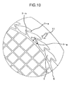
- Fig. 10 shows a fifth embodiment of the air flow rate measuring device according to the present invention, and illustrates only the portion corresponding to the portion A in Fig. 1.
- the grid 7 provided outside the frame 5 is configured to have the beams 7-a each of which is provided with the bent portion 7-h, and has side surfaces at different angles 7-f and 7-g respectively, and the angles 7-f and 7-g are set so that the width of the beams 7-a tapers toward the bent portion 7-h.
- the bent portion 7-h is easily deformed by the radial load 11, and the beams 7-a are more deformable, the effect to absorb the radial load 11 can be enhanced. As a result, a deterioration of the measurement accuracy of the air flow rate measuring device can be prevented.
- Fig. 11 shows a sixth embodiment of the air flow rate measuring device according to the present invention, and illustrates only the portion corresponding to the portion A in Fig. 1.
- the grid 7 provided outside the frame 5 is configured to have the beams 7-a each of which is provided with two bent portions 7-h approximately at an angle of 90 degrees and an approximately semicircular portion 7-m therebetween.
- the semicircular portion 7-m is easily deformed by the radial load 11, and the beams 7-a are more deformable, the effect to absorb the radial load 11 can be enhanced. As a result, a deterioration of the measurement accuracy of the air flow rate measuring device can be prevented.
- Fig. 12 is a sectional view corresponding to Fig. 2 and showing a seventh embodiment of the air flow rate measuring device according to the present invention.
- the rectifier grid 4 has the same configuration as that of the first embodiment shown in Fig. 1, and the rectifier grid 4 is offset from the end surface of the body 1 by a distance m, and is integrally formed with the body 1.
- the rectifier grid 4 is described to have the configuration shown in Fig. 1, but even when the rectifier grid 4 has one of the configurations shown in Figs. 1 to 11, similar functions and effects can be obtained.
- the amount of radial shock load which is generated when the body 1 is dropped down and absorbed by the grid 7 can be reduced.
- This reduces the amount of the angle 7-c of the beams 7-a which changes when the grid 7 absorbs the radial shock load at the time of dropping, and also reduces the concentration of stress at the roots of the beams 7-a when the angle 7-b of the beams 7-a is changed to the angle 7-c.
- the deformation of the grid 7 due to the shock load at the dropping can be reduced, and cracks of the beams 7-a of the grid 7 can be prevented.
- the configuration of the seventh embodiment prevents the radial shock load applied to the peripheral end portion 13 of the body 1 when the body 1 is dropped from being directly transferred to the grid 7, and instead, the longitudinal portion (portion offset by distance m) of the duct 12 is deformed by the shock load, and absorbs the shock load and then transfers it to the grid 7. That is, the radial shock load applied to the peripheral end portion 13 is absorbed by the duct 12 when the duct 12 is deformed by the shock load in the direction from the outer periphery to the center thereof, which restricts the shock loads transferred to the grid 7.
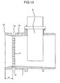
- Fig. 13 is a sectional view corresponding to Fig. 2 and showing an eighth embodiment of the air flow rate measuring device according to the present invention.
- the rectifier grid 4 has the same configuration as that of the first embodiment shown in Fig. 1, and the rectifier grid 4 is offset from the end surface of the body 1 by a distance m, and is integrally formed with the body 1. Also, the rectifier grid 4 has a groove 14 for thickness reduction formed in the side surface around the duct 12 of the body 1.
- the rectifier grid 4 is described to have the configuration shown in Fig. 1, but even when the rectifier grid 4 has one of the configurations shown in Figs. 1 to 11, similar functions and effects can be obtained.
- the amount of the radial shock load which is generated at the periphery 13 of the body 1 when the body 1 is dropped down and absorbed by the grid 7 can be reduced.
- the deformation of the grid 7 due to the shock load at the dropping can be reduced, and cracks of the beams 7-a of the grid 7 can be prevented.
- the groove 14 for thickness reduction also functions to absorb the radial load 11 which is generated when the hose band is tightened, the radial load 11 which is transferred to the grid 7 can be restricted, and the deformation of the grid 7 can be reduced. As a result, the deformation of the grid 7 due to the radial load 11 which is generated when the hose band is tightened is restricted, and cracks at the beams 7-a of the grid 7 can be prevented.
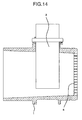
- Fig. 14 is a sectional view corresponding to Fig. 2 and showing a ninth embodiment of the air flow rate measuring device according to the present invention.
- the rectifier grid 4 has one of the configurations shown in Figs. 1 to 11, and the rectifier grid 4 is disposed downstream of the module 2 which has the sensing element for sensing the air flow, and is integrally formed with the body 1.
- Fig. 15 is a front view of a tenth embodiment of the air flow rate measuring device according to the present invention, viewed from the upstream side of the air flow.
- the rectifier grid 4 has one of the configurations shown in Figs. 1 to 11, and the rectifier grid 4 is separately formed from the body 1 and is fixed to the body 1 by means of adhesive, welding, pressing, or the like so that the body 1 supports the rectifier grid 4.
- Fig. 16 is a front view of an eleventh embodiment of the air flow rate measuring device according to the present invention, viewed from the upstream side of the air flow.
- the grid 7 having one of the configurations shown in Figs. 1 to 11 is provided to the frame 5 which has an elliptical shape similar to the elliptical cross-section of the body 1 as the main passage for the intake air flow, and the frame 5 includes the mesh grid 6 therein.
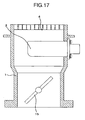
- Fig. 17 is a front view of a twelfth embodiment of the air flow rate measuring device according to the present invention, viewed from the upstream side of the air flow.
- the rectifier grid 4 having one of the configurations shown in Figs. 1 to 11 is provided to the body 1 which has a valve 15 therein for regulating the air flow.
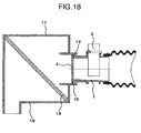
- Fig. 18 is a sectional view corresponding to Fig. 4 and showing the layout of an example of an automobile air intake system in which a thirteenth embodiment of the air flow rate measuring device according to the present invention is used.
- an air flow rate measuring device having the rectifier grid 4 having one of the configurations shown in Figs. 1 to 11 includes the duct 12 of the body 1 connected to the clean side 17 of an air cleaner via a seal component 16. Upstream of the clean side 17, the air cleaner is provided with an air filter 18, and has a dirty side 19.
- the present invention relates to an air flow rate measuring device and an air flow measuring passage, in particular preferably to a thermal type air flow rate measuring device and passage for measuring the air flow supplied to an internal combustion engine of an automobile.
Landscapes
- Physics & Mathematics (AREA)
- Fluid Mechanics (AREA)
- General Physics & Mathematics (AREA)
- Measuring Volume Flow (AREA)
Abstract
Description
- The present invention relates to an air flow rate measuring device, and in particular to an air flow rate measuring device for measuring the air flow which is supplied to an internal combustion engine of an automobile, and a flow rate measuring passage therefor.
- Generally, a metal mesh, an aluminum honeycomb or a plastic is used to form a rectifier grid of an air flow rate measuring device. In the case of a plastic molding, as described in
Japanese Patent NO. 3245362 - In the prior art, a deformation of the second rib grid leads to a deformation of the first mesh grid, and also a deformation of the second rib grid at the beginning of the tightening of a hose band or due to the radial load caused by a thermal factor causes a problem of deterioration of the measurement accuracy of the air flow rate measuring device. In addition, the second rib grid is formed to have a sufficient thickness to maintain the mechanical strength of the rib grid, which results in a large pressure loss across the grid.
- Therefore, there is a need for providing an air flow rate measuring device in which deterioration of its measurement accuracy can be prevented and a reduction of the pressure loss across the grid can be achieved in association with the radial load which is generated by the tightening of a hose band.
- The tightening of a hose band generates two types of radial loads: one type is the load applied due to a configuration factor at the beginning of the tightening of the hose band, and another type is the load caused by a thermal factor, that is the difference in coefficient of linear thermal expansion between the hose band and the body and the rectifier grid due to temperature changes. Therefore, the radial loads due to the two factors generate a stress which causes a deformation of the grid, and the deformation should be taken into the consideration to address the problem which is caused by the radial load at tightening the hose band. In addition, because a resin may exhibit creeps, a deformation of the grid caused by a creep also should be taken into the consideration to address the problem.
- One problem to be solved by the present invention is to provide a flow measuring device or a flow measuring passage having grids which are not easily deformed.
- The above problem is solved according to the independent claims. The dependent claims relate to preferred embodiments of the concept of the present invention.
- For example, the above object can be achieved by a flow measuring device in which a grid includes a first grid portion and a second grid portion between the first grid portion and a passage forming component, and the second grid portion is more easily deformed than the first grid portion.
- The present invention can provide an air flow rate measuring device of high performance and high reliability which reduces the pressure loss across the grid due to the load which is generated at the tightening of a hose band, prevents the deterioration of the measurement accuracy of the air flow rate measuring device which is caused by the grid deformation, and enables the grid to have a configuration which results in a smaller pressure loss and high reliability.
- Other objects, features and advantages of the invention will become apparent from the following description of embodiments of the invention taken in conjunction with the accompanying drawings.
-
- Fig. 1 is a front view of a first embodiment of an air flow rate measuring device according to the present invention, viewed from the upstream side of the air flow;
- Fig. 2 is a sectional view taken along the line II-II in Fig. 1;
- Fig. 3 is an enlarged view of the portion A in Fig. 1;
- Fig. 4 is a sectional view showing an example of the layout of an automobile air intake system in which the first embodiment of the air flow rate measuring device according to the present invention is used;
- Fig. 5 is a sectional view taken along the line V-V in Fig. 4;
- Fig. 6 is an enlarged view of the portion A in Fig. 1 and showing the first embodiment of the air flow rate measuring device, before and after a durability test, which is mounted to the air intake system shown in Fig. 4;
- Fig. 7 is an enlarged view corresponding to Fig. 3 and showing a second embodiment of the air flow rate measuring device according to the present invention;
- Fig. 8 is an enlarged view corresponding to Fig. 3 and showing a third embodiment of the air flow rate measuring device according to the present invention;
- Fig. 9 is an enlarged view corresponding to Fig. 3 and showing a fourth embodiment of the air flow rate measuring device according to the present invention;
- Fig. 10 is an enlarged view corresponding to Fig. 3 and showing a fifth embodiment of the air flow rate measuring device according to the present invention;
- Fig. 11 is an enlarged view corresponding to Fig. 3 and showing a sixth embodiment of the air flow rate measuring device according to the present invention;
- Fig. 12 is a sectional view corresponding to Fig. 2 and showing a seventh embodiment of the air flow rate measuring device according to the present invention;
- Fig. 13 is a sectional view corresponding to Fig. 2 and showing an eighth embodiment of the air flow rate measuring device according to the present invention;
- Fig. 14 is a sectional view corresponding to Fig. 2 and showing a ninth embodiment of the air flow rate measuring device according to the present invention;
- Fig. 15 is a front view of a tenth embodiment of the air flow rate measuring device according to the present invention, viewed from the upstream side of the air flow;
- Fig. 16 is a front view of an eleventh embodiment of the air flow rate measuring device according to the present invention, viewed from the upstream side of the air flow;
- Fig. 17 is a sectional view corresponding to Fig. 2 and showing a twelfth embodiment of the air flow rate measuring device according to the present invention; and
- Fig. 18 is a sectional view corresponding to Fig. 4 and showing the layout of an example of an automobile air intake system in which a thirteenth embodiment of the air flow rate measuring device according to the present invention is used.
- Now, embodiments of the present invention will be described hereinafter with reference to the accompanying drawings.
- Fig. 1 is a front view of a first embodiment of an air flow rate measuring device according to the present invention, viewed from the upstream side of the air flow. Fig. 2 is a sectional view taken along the line II-II in Fig. 1. Fig. 3 is an enlarged view of the portion A in Fig. 1. Fig. 4 is a sectional view showing an example of the layout of an automobile air intake system in which the first embodiment of the air flow rate measuring device according to the present invention is used. Fig. 5 is a sectional view taken along the line V-V in Fig. 4. Fig. 6 is an enlarged view of the portion A in Fig. 1 and showing the first embodiment of the air flow rate measuring device, before and after a durability test, which is mounted to the air intake system shown in Fig. 4.
- The air flow rate measuring device comprises a
body 1 which has a circular cross section and forms a main passage for the intake air flow and amodule 2 including a sensing element for sensing the air flow, and thebody 1 and themodule 2 are fixed to each other byscrews 3. In the present embodiment, thescrews 3 are used to fix thebody 1 and themodule 2, but thebody 1 and themodule 2 may be fixed to each other by welding or adhesive for example other than the screws, to have similar function and effect. - A
rectifier grid 4 is provided inside thebody 1 upstream of themodule 2 substantially perpendicular to theair flow 8. Therectifier grid 4 is arranged close to theupstream duct 12 of thebody 1, and therectifier grid 4 and thebody 1 are integrally formed with each other by plastic. - The
rectifier grid 4 comprises acircular frame 5, amesh grid 6 and agrid 7. Thecircular frame 5 has a shape similar to the cross section of thebody 1 and a diameter smaller than that of the inner diameter of thebody 1. Themesh grid 6 is provided inside thecircular frame 5 and is intended to rectify theair flow 8. Thegrid 7 has beams 7-a equiangularly spaced from each other. Each of the beams 7-a is arranged with an angle 7-b relative to a normal line 7-i which extends to the center of thecircular frame 5. Therectifier grid 4 is formed by integrally forming thecircular frame 5, themesh grid 6, and thegrid 7. - One ends of the beams 7-a which are an end face of the
rectifier grid 4 are arranged to thebody 1 so that therectifier grid 4 is fixed to and supported by thebody 1. In other words, thecircular frame 5 having themesh grid 6 therein is integrally and fixedly supported by thebody 1 via both ends of each of the beams 7-a which is disposed between thebody 1 and thecircular frame 5, that is, via thegrid 7. Further, theframe 5 is approximately concentrically disposed within thebody 1. - The
duct 12 of thebody 1 is inserted into a rubber duct 9, and ametallic hose band 10 is tightened around the rubber duct 9 to fix the rubber duct 9 to thebody 1. - The above configuration causes a
radial load 11 from the outer periphery toward the center of thebody 1 at the beginning of the tightening of thehose band 10, and theradial load 11 is transferred from the entire outer periphery to the rubber duct 9 and theduct 12 of thebody 1. In addition, anotherradial load 11 from the outer periphery toward the center of thebody 1 is caused due to a thermal factor, that is the difference in the coefficient of linear thermal expansion among the hose band and the body and the rectifier grid due to temperature changes, and transferred from the entire outer periphery to the rubber duct 9 and theduct 12 of thebody 1. - In the present embodiment, the beams 7-a are provided outside of the
frame 5 of therectifier grid 4 at the angle 7-b with respect to theradial load 11, and therefore the beams 7-a do not become struts against theradial load 11. In addition, the angle 7-b of the beams 7-a is changed to an angle 7-c due to theradial load 11, which allows the beams 7-a to absorb theradial load 11. This prevents the transfer of theradial load 11 to themesh grid 6 via the beams 7-a. That is, thegrid 7 outside of theframe 5 is configured to be easily deformed by theradial load 11 to a grid shape 7-d so as to enable thegrid 7 to absorb theradial load 11. - This restrains the deformation of the
mesh grid 6 inside theframe 5 which is caused by theradial load 11 when the hose band is tightened, and also prevents deterioration of the measurement accuracy of the device. - The
rectifier grid 4 which is configured to absorb theradial load 11 by the deformation of thegrid 7 makes it possible to reduce the mechanical strength of the rectifier grid itself. Thus, the strength required for themesh grid 6 in the direction of its width 6-a can be reduced. The strengths required for theframe 5 and thegrid 7 also can be reduced, so that the width 5-a of theframe 5 and the width 7-j of the beams 7-a can be approximately as thin as the width 6-a of themesh grid 6, and the pressure loss across therectifier grid 4 can be reduced. - For example, when the
mesh grid 6 needs to have the minimum width 6-a of 0.4 mm for rectifying effect, themesh grid 6 can have the same minimum width 6-a of 0.4 mm. Also, the width 5-a of theframe 5 and the width 7-j of the beams 7-a may be thin within a range from 0.4 mm, which is equal to the minimum width 6-a of themesh grid 6, to 0.5 mm, which is about 1.25 times that of the minimum width 6-a, and this configuration reduces the pressure loss across therectifier grid 4 while maintaining the rectifying effect. - Each of the beams 7-a has a chamfered portion 7-e at the roots of both ends thereof. This relieves concentration of stress at the roots of both ends which is generated when the angle 7-b of the beams 7-a is changed to the angle 7-c. In addition, the
rectifier grid 4 can be molded to have wide apertures at the beams 7-a, which improves its moldability. - The above configuration relieves the concentration of stress and prevents cracks due to the deformation, as well as improves its moldability. In the present embodiment, the
frame 5 is approximately concentrically disposed within thebody 1, but even when the center of theframe 5 is offset from that of thebody 1 for example, the device has similar functions and effects, which prevents deterioration of its measurement accuracy, reduces pressure loss, prevents cracks, and improves its moldability while maintaining the rectifying effect. - In the present embodiment, since the
grid 7 provided outside theframe 5 of therectifier grid 4 has the beams 7-a which are approximately equiangularly spaced and are inclined in substantially the same direction, thegrid 7 can be a substantially regular and uniform grid arrangement. - As a result, when the
air flow 8 passes through thegrid 7, theair flow 8 can be stabilized, and the measurement accuracy of the device can be improved. - After a certain time duration, although the
grid 7 absorbs theradial load 11 and is deformed due to theradial load 11, the deformed grid configuration 7-d can be also substantially regular and uniform. - Therefore, when the
air flow 8 passes through the deformed grid 7-d after a certain time duration, theair flow 8 can be still stabilized, and a deterioration of the measurement accuracy of the device can be prevented. - Furthermore, in the present embodiment, the
frame 5 of therectifier grid 4 has substantially the same circular cross-sectional shape as thebody 1 and is substantially concentrically disposed within thebody 1, which enables the tiltedgrid 7 to have a substantially regular and uniform grid arrangement. And the deformed and tilted grid configuration 7-d due to theradial load 11 after a certain time duration can be also regular and uniform. This achieves an improvement of the measurement accuracy of the device, and prevents a deterioration of the measurement accuracy of the device. - According to the above configuration, the deformation of the
mesh grid 6 in therectifier grid 4 due to theradial load 11 at the beginning of tightening of a hose band or the thermal factor and its creep can be prevented, and the width 6-a of themesh grid 6, the width 5-a of theframe 5, and the width 7-j of the beams 7-a of therectifier grid 4 can be thinner. In addition, the tilted configuration of thegrid 7 of therectifier grid 4 can be regular and uniform, and the deformed grid 7-d due to theradial load 11 can have also a regular and uniform grid arrangement. - Therefore, the above configuration prevents a deterioration of the measurement accuracy of the air flow rate measuring device, reduces the pressure loss across the device, and also improves the measurement accuracy, and thus provides an air flow rate measuring device of high performance and high reliability.
- Fig. 7 shows a second embodiment of the air flow rate measuring device according to the present invention, and illustrates only the portion corresponding to the portion A in Fig. 1.
- In the second embodiment, the
grid 7 provided outside theframe 5 is configured to have beams 7-a which are arranged at an acute angle 7-b of 45 degrees or less relative to the normal direction 7-i toward the center of theframe 5. - According to the above configuration, since the
grid 7 is easily deformed by theradial load 11, the effect to absorb theradial load 11 can be enhanced. The more acute the angle 7-b is, the more easily deformed thegrid 7 is by theradial load 11, which also enhances the effect to absorb theradial load 11. As a result, a deterioration of the measurement accuracy of the air flow rate measuring device can be prevented. - Fig. 8 shows a third embodiment of the air flow rate measuring device according to the present invention, and illustrates only the portion corresponding to the portion A in Fig. 1.
- In the third embodiment, the
grid 7 provided outside theframe 5 is configured to have beams 7-a which are arranged at a tilted angle relative to the normal direction 7-i which extends toward the center of theframe 5. Each of the beams 7-a has side surfaces which are tilted at different angles 7-f and 7-g respectively. The angles 7-f and 7-g are set so that the width of each of the beams 7-a tapers from the outer peripheral toward the center of theframe 5. That is, each of the beams 7-a has tilted side surfaces at different angles 7-f and 7-g respectively, and the angles 7-e and 7-f are set so that the width at both ends of each of the beams 7-a tapers from thebody 1 toward theframe 5. In other words, thegrid 7 is configured to have beams 7-a so that the width 7-k of the beams 7-a on theframe 5 side is less than the width 7-1 of the beams 7-a on the side of thebody 1. - According to the above configuration, since the width of the beams 7-a which are provided between the
body 1 and theframe 5 is set so that the width 7-k of the beams 7-a on theframe 5 side is less than the width 7-1 of the beams 7-a on thebody 1 side, the inner portion of beams 7-a on the width 7-k side which is close to theframe 5 is more easily deformed by theradial load 11, which enhances the effect to absorb theradial load 11. Also, the molding with a molten plastic which flows from thebody 1 to therectifier grid 4 can be achieved to provide wide apertures at the beams 7-a, which improves the moldability of therectifier grid 4. - Therefore, the above configuration prevents a deterioration of the measurement accuracy of the air flow rate measuring device, while improving the moldability.
- Fig. 9 shows a fourth embodiment of the air flow rate measuring device according to the present invention, and illustrates only the portion corresponding to the portion A in Fig. 1.
- In the fourth embodiment, the
grid 7 provided outside theframe 5 is configured to have the beams 7-a having a bent portion 7-h. - According to the above configuration, since the bent portion 7-h is easily deformed by the
radial load 11, and the beams 7-a are more deformable, the effect to absorb theradial load 11 can be enhanced. As a result, a deterioration of the measurement accuracy of the air flow rate measuring device can be prevented. - Fig. 10 shows a fifth embodiment of the air flow rate measuring device according to the present invention, and illustrates only the portion corresponding to the portion A in Fig. 1.
- In the fifth embodiment, the
grid 7 provided outside theframe 5 is configured to have the beams 7-a each of which is provided with the bent portion 7-h, and has side surfaces at different angles 7-f and 7-g respectively, and the angles 7-f and 7-g are set so that the width of the beams 7-a tapers toward the bent portion 7-h. - According to the above configuration, since the bent portion 7-h is easily deformed by the
radial load 11, and the beams 7-a are more deformable, the effect to absorb theradial load 11 can be enhanced. As a result, a deterioration of the measurement accuracy of the air flow rate measuring device can be prevented. - Fig. 11 shows a sixth embodiment of the air flow rate measuring device according to the present invention, and illustrates only the portion corresponding to the portion A in Fig. 1.
- In the sixth embodiment, the
grid 7 provided outside theframe 5 is configured to have the beams 7-a each of which is provided with two bent portions 7-h approximately at an angle of 90 degrees and an approximately semicircular portion 7-m therebetween. - According to the above configuration, since the semicircular portion 7-m is easily deformed by the
radial load 11, and the beams 7-a are more deformable, the effect to absorb theradial load 11 can be enhanced. As a result, a deterioration of the measurement accuracy of the air flow rate measuring device can be prevented. - Fig. 12 is a sectional view corresponding to Fig. 2 and showing a seventh embodiment of the air flow rate measuring device according to the present invention.
- In the seventh embodiment, the
rectifier grid 4 has the same configuration as that of the first embodiment shown in Fig. 1, and therectifier grid 4 is offset from the end surface of thebody 1 by a distance m, and is integrally formed with thebody 1. - In the seventh embodiment, the
rectifier grid 4 is described to have the configuration shown in Fig. 1, but even when therectifier grid 4 has one of the configurations shown in Figs. 1 to 11, similar functions and effects can be obtained. - According to the above configuration, the amount of radial shock load which is generated when the
body 1 is dropped down and absorbed by thegrid 7 can be reduced. This in turn reduces the amount of the angle 7-c of the beams 7-a which changes when thegrid 7 absorbs the radial shock load at the time of dropping, and also reduces the concentration of stress at the roots of the beams 7-a when the angle 7-b of the beams 7-a is changed to the angle 7-c. Thus, the deformation of thegrid 7 due to the shock load at the dropping can be reduced, and cracks of the beams 7-a of thegrid 7 can be prevented. - In other words, when the
body 1 is dropped down with therectifier grid 4 which is disposed on the upstream side of thebody 1 being directed downward, thebody 1 is dropped with theperipheral end portion 13 being the first portion to be landed. However, the configuration of the seventh embodiment prevents the radial shock load applied to theperipheral end portion 13 of thebody 1 when thebody 1 is dropped from being directly transferred to thegrid 7, and instead, the longitudinal portion (portion offset by distance m) of theduct 12 is deformed by the shock load, and absorbs the shock load and then transfers it to thegrid 7. That is, the radial shock load applied to theperipheral end portion 13 is absorbed by theduct 12 when theduct 12 is deformed by the shock load in the direction from the outer periphery to the center thereof, which restricts the shock loads transferred to thegrid 7. - Therefore, the longer the offset distance m is, the more load is restricted from being transferred to the
grid 7. - Fig. 13 is a sectional view corresponding to Fig. 2 and showing an eighth embodiment of the air flow rate measuring device according to the present invention.
- In the eighth embodiment, the
rectifier grid 4 has the same configuration as that of the first embodiment shown in Fig. 1, and therectifier grid 4 is offset from the end surface of thebody 1 by a distance m, and is integrally formed with thebody 1. Also, therectifier grid 4 has agroove 14 for thickness reduction formed in the side surface around theduct 12 of thebody 1. - In the eighth embodiment, the
rectifier grid 4 is described to have the configuration shown in Fig. 1, but even when therectifier grid 4 has one of the configurations shown in Figs. 1 to 11, similar functions and effects can be obtained. - According to the above configuration, the amount of the radial shock load which is generated at the
periphery 13 of thebody 1 when thebody 1 is dropped down and absorbed by thegrid 7 can be reduced. This in turn reduces the amount of the angle 7-c of the beams 7-a which changes when thegrid 7 absorbs the radial shock load at the time of dropping, and also reduces the concentration of stress at the roots of the beams 7-a when the angle 7-b of the beams 7-a is changed to the angle 7-c. Thus, the deformation of thegrid 7 due to the shock load at the dropping can be reduced, and cracks of the beams 7-a of thegrid 7 can be prevented. - Since the
groove 14 for thickness reduction also functions to absorb theradial load 11 which is generated when the hose band is tightened, theradial load 11 which is transferred to thegrid 7 can be restricted, and the deformation of thegrid 7 can be reduced. As a result, the deformation of thegrid 7 due to theradial load 11 which is generated when the hose band is tightened is restricted, and cracks at the beams 7-a of thegrid 7 can be prevented. - Fig. 14 is a sectional view corresponding to Fig. 2 and showing a ninth embodiment of the air flow rate measuring device according to the present invention.
- In the ninth embodiment, the
rectifier grid 4 has one of the configurations shown in Figs. 1 to 11, and therectifier grid 4 is disposed downstream of themodule 2 which has the sensing element for sensing the air flow, and is integrally formed with thebody 1. - Even when the
rectifier grid 4 is disposed downstream of themodule 2 as in the ninth embodiment, similar functions and effects can be obtained to those described in connection with Figs. 1 to 11. - Fig. 15 is a front view of a tenth embodiment of the air flow rate measuring device according to the present invention, viewed from the upstream side of the air flow.
- In the tenth embodiment, the
rectifier grid 4 has one of the configurations shown in Figs. 1 to 11, and therectifier grid 4 is separately formed from thebody 1 and is fixed to thebody 1 by means of adhesive, welding, pressing, or the like so that thebody 1 supports therectifier grid 4. - Even when the
rectifier grid 4 is separately formed from thebody 1 as in the tenth embodiment, similar functions and effects can be obtained to those described in connection with Figs. 1 to 11. - Fig. 16 is a front view of an eleventh embodiment of the air flow rate measuring device according to the present invention, viewed from the upstream side of the air flow.
- In the eleventh embodiment, the
grid 7 having one of the configurations shown in Figs. 1 to 11 is provided to theframe 5 which has an elliptical shape similar to the elliptical cross-section of thebody 1 as the main passage for the intake air flow, and theframe 5 includes themesh grid 6 therein. - Even when the body has an elliptical cross-section as in the eleventh embodiment, similar functions and effects can be obtained to those described in connection with Figs. 1 to 11.
- Fig. 17 is a front view of a twelfth embodiment of the air flow rate measuring device according to the present invention, viewed from the upstream side of the air flow.
- In the twelfth embodiment, the
rectifier grid 4 having one of the configurations shown in Figs. 1 to 11 is provided to thebody 1 which has avalve 15 therein for regulating the air flow. - Even when the
rectifier grid 4 is provided to thebody 1 having thevalve 15 as in the twelfth embodiment, similar functions and effects can be obtained to those described in connection with Figs. 1 to 11. - Fig. 18 is a sectional view corresponding to Fig. 4 and showing the layout of an example of an automobile air intake system in which a thirteenth embodiment of the air flow rate measuring device according to the present invention is used.
- In the thirteenth embodiment, an air flow rate measuring device having the
rectifier grid 4 having one of the configurations shown in Figs. 1 to 11 includes theduct 12 of thebody 1 connected to theclean side 17 of an air cleaner via aseal component 16. Upstream of theclean side 17, the air cleaner is provided with anair filter 18, and has adirty side 19. - Similar functions and effects can be obtained to those described in connection with Figs. 1 to 11 with respect to the radial load which is generated when the
seal component 16 is assembled. - The present invention relates to an air flow rate measuring device and an air flow measuring passage, in particular preferably to a thermal type air flow rate measuring device and passage for measuring the air flow supplied to an internal combustion engine of an automobile.
- It should be further understood by those skilled in the art that although the foregoing description has been made with reference to embodiments of the invention, the invention is not limited thereto, and various changes and modifications may be made without departing from the spirit of the invention and the scope of the appended claims.
-
- 1
- body
- 2
- module
- 3
- screws
- 4
- rectifier grid
- 5
- frame
- 5-a
- width (of frame 5)
- 6
- mesh grid
- 6-a
- width (of mesh grid 6)
- 7
- grid
- 7-a
- beam
- 7-b
- angle
- 7-c
- angle
- 7-d
- grid shape (deformed grid 7)
- 7-e
- angle
- 7-f
- angle (tilted)
- 7-g
- angle (tilted)
- 7-h
- bent portion
- 7-i
- normal line
- 7-j
- width (of beams 7-a)
- 7-k
- width (of beams 7-a on
frame 5 side) - 7-1
- width (of beams 7-a on
body 1 side) - 7-m
- semicircular portion
- 8
- air flow
- 9
- rubber duct
- 10
- hose band
- 11
- radial load
- 12
- duct (of body 1)
- 13
- peripheral end portion (of body 1)
- 14
- groove
- 15
- valve
- 16
- seal component
- 17
- clean side (of air cleaner)
- 18
- air filter
- 19
- dirty side (of air cleaner)
- m
- offset distance
Claims (37)
- Flow rate measuring device, comprising:a flow rate measuring module (2) into which a gas is introduced and which measures the flow rate of the gas, a passage forming component (1, 12) which forms a passage; and a grid (4) which crosses the passage, in which a part of the flow rate measuring module (2) is inserted through an opening provided in the passage forming component (1, 12) to be fixed therein,wherein the grid (4) includes a first grid portion (6) and a second grid portion (7) between the first grid portion (6) and the passage forming component (1, 12), and the second grid portion (7) is formed to be more easily deformable than the first grid portion (6).
- Flow rate measuring device according to claim 1, wherein the second grid portion (7) is formed by only grids which are tilted relative to normal directions to the outer periphery of the first grid portion (6).
- Flow rate measuring device according to claim 1, wherein the second grid portion (7) is formed by only grids which are tilted relative to normal directions to the inner periphery of the passage forming component (1, 12).
- Flow rate measuring device according to claim 1, wherein the second grid portion (7) is formed by grids at an intermediate of each of which a bent portion is provided.
- Flow rate measuring device according to any of claims 1 to 4, wherein the first grid portion (6) is disposed at a position including the central axis of the passage (1, 12), and the second grid portion (7) is formed so as to surround the first grid portion (6).
- Flow rate measuring device according to any of claims 1 to 5, wherein there is provided a component (5) which connects between the first grid portion (6) and the second grid portion (7) or between the second grid portion (7) and the passage forming component (1, 12).
- Flow rate measuring device according to any of claims 1 to 6, wherein the measuring module (2) has an auxiliary passage wherein a thermal measuring component is disposed, and the measuring module (2) is fixed so that the entrance of the auxiliary passage is positioned downstream of the first grid portion (6).
- Flow rate measuring device, comprising: a flow rate measuring module (2) into which a gas is introduced and which measures the flow rate of the gas, a passage forming component (1, 12) which forms a passage, and a grid (4) which crosses the passage, in which a part of the flow rate measuring module (2) is inserted through an opening provided in the passage forming component (1, 12) to be fixed therein,
wherein there are provided means (7-a) converting a deformation of the passage forming component (1, 12) into a rotation of the grid (4). - Flow rate measuring device according to claim 8, wherein the converting means (7-a) are provided between the grid (4, 6) and the passage forming component (1, 12) and are configured with a plurality of beams(7-a) which are generally arranged spirally or in a bent form.
- Flow rate measuring device, comprising: a flow rate measuring module (2) into which a gas is introduced and which measures the flow rate of the gas, a passage forming component 81, 12) which forms a passage, and a grid (4) which crosses the passage, in which a part of the flow rate measuring module (2) is inserted through an opening provided in the passage forming component (1, 12) to be fixed therein,
wherein a plurality of beams (7-a) are provided between the grid (4, 6) and the passage forming component (1, 12) and are all arranged so as to be tilted relative to normal directions to the outer periphery of the grid (6). - Flow rate measuring device according to claim 10,
wherein the plurality of beams (7-a) are formed so that the tilt angles (7-b) of the beams (7-a) are substantially constant, and the spacings between the beams (7-a) are substantially constant. - Flow rate measuring device, comprising: a flow rate measuring module (2) into which a gas is introduced and which measures the flow rate of the gas, a passage forming component (1, 12) which forms a passage, and a grid (4) which crosses the passage, in which a part of the flow rate measuring module (2) is inserted through an opening provided in the passage forming component (1, 12) to be fixed therein,
wherein a plurality of beams (7-a) are provided between the grid (4, 6) and the passage forming component (1, 12) and are all arranged so as to be tilted relative to normal directions to the inner periphery of the passage forming component (1, 12). - Flow rate measuring device according to claim 12,
wherein the plurality of beams (7-a) are formed so that the tilt angles (7-b) of the beams (7-a) are substantially constant, and the spacings between the beams (7-a) are substantially constant. - Flow rate measuring device according to any of claims 1 to 13, wherein the device is connected to an air intake system of an internal combustion engine.
- Flow rate measuring passage, comprising: a passage forming component (1, 12) which forms a passage, and a grid (4) which crosses the passage, in which a part of a flow measuring module (2) into which a gas is introduced and which measures the flow rate of the gas is inserted through an opening formed in the passage forming component (1, 12) to be fixed therein, wherein grid (4) includes a first grid portion (6) and a second grid portion (7) between the first grid portion (6) and the passage forming component (1, 12), and the second grid portion (7) is formed to be more easily deformable than the first grid portion (6).
- Flow rate measuring passage according to claim 15, wherein the second grid portion (7) is formed by only grids which are tilted relative to normal directions to the outer periphery of the first grid portion (6).
- Flow rate measuring passage according to claim 15, wherein the second grid portion (7) is formed by only grids which are tilted relative to normal directions to the inner periphery of the passage forming component (1, 12).
- Flow rate measuring passage according to claim 15, wherein the second grid portion (7) is formed by grids at an intermediate of each of which a bent portion is provided.
- Flow rate measuring passage according to claim 15, wherein the first grid portion (6) is disposed at a position including the central axis of the passage, and the second grid portion (7) is formed so as to surround the first grid portion (6).
- Flow rate measuring passage according to claim 15, wherein there is provided a component which connects between the first grid portion (6) and the second grid portion (7) or between the second grid portion (7) and the passage forming component (1, 12).
- Flow rate measuring passage according to any of claims 15 to 20, wherein the measuring module (2) has an auxiliary passage wherein a thermal measuring component is disposed, and the measuring module (2) is fixed so that the entrance of the auxiliary passage is positioned downstream of the first grid portion (6) and is connected to an air intake system of an internal combustion engine.
- Flow rate measuring passage, comprising: a passage forming component (1, 12) which forms a passage, and a grid (4) which crosses the passage, in which a part of a measuring module (2) into which gas is introduced and which measures the flow rate of the gas is inserted through an opening provided in the passage forming component (1, 12) to be fixed therein,
wherein there are provided means (7-a) for converting a deformation of the passage forming component (1, 12) into a rotation of the grid (4). - Flow rate measuring passage according to claim 22, wherein the converting means (7-a) are provided between the grid (4, 6) and the passage forming component (1, 12) and are configured with a plurality of beams (7-a) which are generally arranged spirally or in a bent form.
- Flow rate measuring passage, comprising: a passage forming component (1, 12) which forms a passage, and a grid (4) which crosses the passage, in which a part of a measuring module (2) into which a gas is introduced and which measures the flow rate of the gas is inserted through an opening provided in the passage forming component (1, 12) to be fixed therein,
wherein a plurality of beams (7-a) are provided between the grid (4, 6) and the passage forming component (1, 12) and are all arranged so as to be tilted relative to normal directions to the outer periphery of the grid (4, 6). - Flow rate measuring passage according to claim 24, wherein the plurality of beams (7-a) are formed so that the tilt angles (7-b) of the beams (7-a) are substantially constant, and the spacings between the beams (7-a) are substantially constant.
- Flow rate measuring passage, comprising: a passage forming component (1, 12) which forms a passage, and a grid (4) which crosses the passage, in which a part of a measuring module (2) into which a gas is introduced and which measures the flow rate of the gas is inserted through an opening provided in the passage forming component (1, 12) to be fixed therein,
wherein a plurality of beams (7-a) are provided between the grid (4, 6) and the passage forming component (1, 12) and are all arranged so as to be tilted relative to normal directions to the inner periphery of the passage forming component (1, 12). - Flow rate measuring passage according to claim 26, wherein the plurality of beams (7-a) are formed so that the tilt angels (7-b) of the beams (7-a) are substantially constant, and the spacings between the beams (7-a) are substantially constant.
- Air flow rate measuring device for measuring the air flow into an internal combustion engine, wherein a component (1, 12) which forms an air passage for the air flow (8) is formed with a grid (4) disposed upstream or downstream of a flow rate sensing portion, the grid (4) comprising: a frame (5) arranged inside the air passage, a mesh grid (6) arranged inside the frame (5), and beams (7-a) arranged between the air passage forming component (1, 12) and the frame (5), each of the beams (7-a) having an angle with respect to radial directions of the frame (5), the grid (4, 6) being integrally formed with the component (1, 12).
- Air flow rate measuring device according to claim 28, wherein the beams (7-a) are tilted in the same directions relative to radial directions of the frame (5), the grid (4, 6) being integrally formed with the component (1, 12).
- Air flow rate measuring device according to claim 29, wherein the beams (7-a) have, in the same directions, angles with respect to radial directions of the frame (5), the grid (4, 6) being integrally formed with the component (1, 12).
- Air flow rate measuring device for measuring the air flow into an internal combustion engine, wherein a component (1, 12) which forms an air passage for the air flow (8) is formed with a grid (4) disposed upstream or downstream of a flow rate sensing portion, the grid (4) comprising: a frame (5) arranged inside the air passage, a mesh grid (6) arranged inside the frame (5), and beams (7-a) arranged between the air passage forming component (1, 12) and the frame (5), each of the beams (7-a) having one or more bent portions, the grid (4, 6) being integrally formed with the component.
- Air flow rate measuring device according to any one of claims 28 to 31, wherein the air passage forming component (1, 12), the frame (5), the beams (7-a) and the mesh grid (6) are integrally formed with one another.
- Air flow rate measuring device according to claim 32, wherein the grid (4) comprising the frame (5), the beams (7-a) and the mesh grid (6) is offset from an end surface of the air passage forming component (1, 12).
- Air flow rate measuring device according to claim 32, wherein a groove (14) for thickness reduction is formed in a side surface of the air passage forming component (1, 12) around the position where the grid comprising the frame (5), the beams (7-a) and the mesh grid (6) is mounted.
- The air flow rate measuring device according to any one of claims 28 to 31, wherein the frame has substantially the same shape to the cross-section of the air passage forming component, and is substantially concentrically disposed within the air passage forming component.
- Air flow rate measuring device, comprising: a flow rate sensing portion (2) for measuring the flow rate of intake air of an internal combustion engine; a body (1) which has a circular or elliptical cross section and forms a main air passage for the intake air, and a grid (4) disposed upstream or downstream of the flow rate sensing portion (2), wherein the grid (4) comprises: a circular or elliptical frame (5) which has a substantially identical shape to that of the body (1) and is substantially concentrically disposed within the body (1), a mesh grid (6) in the frame (5), and beams (7-a) between the body (1) and the frame (5), the beams (7-a) being substantially equally spaced from each other and being arranged in substantially the same direction at an acute angle (7-b) relative to radial directions of the frame (5), the body (1) and the grid (4) including the frame (5), the beams (7-a) and the mesh grid (6) being integrally formed with each other.
- Air flow rate measuring device according to claim 36, wherein the beams (7-a) have side surfaces which are tilted at different angles, and the angles are set so that the width of the beams (7-j) tapers from the inner peripheral portion of the body toward the frame (5).
Applications Claiming Priority (1)
| Application Number | Priority Date | Filing Date | Title |
|---|---|---|---|
| JP2006156753A JP4341645B2 (en) | 2006-06-06 | 2006-06-06 | Flow measuring device, flow measuring passage and air flow measuring device |
Publications (2)
| Publication Number | Publication Date |
|---|---|
| EP1867961A1 true EP1867961A1 (en) | 2007-12-19 |
| EP1867961B1 EP1867961B1 (en) | 2017-04-12 |
Family
ID=38599381
Family Applications (1)
| Application Number | Title | Priority Date | Filing Date |
|---|---|---|---|
| EP07011140.6A Ceased EP1867961B1 (en) | 2006-06-06 | 2007-06-06 | Air flow rate measuring device and passage |
Country Status (3)
| Country | Link |
|---|---|
| US (1) | US7437926B2 (en) |
| EP (1) | EP1867961B1 (en) |
| JP (1) | JP4341645B2 (en) |
Cited By (3)
| Publication number | Priority date | Publication date | Assignee | Title |
|---|---|---|---|---|
| WO2009065680A1 (en) * | 2007-11-19 | 2009-05-28 | Robert Bosch Gmbh | Sensor arrangement for determining a parameter of a fluid medium |
| EP3048432A1 (en) * | 2015-01-22 | 2016-07-27 | Sensirion AG | Flow grid for flow sensor device |
| US10942139B2 (en) | 2017-06-30 | 2021-03-09 | Sensirion Ag | Operation method for flow sensor device |
Families Citing this family (4)
| Publication number | Priority date | Publication date | Assignee | Title |
|---|---|---|---|---|
| JP2009014601A (en) * | 2007-07-06 | 2009-01-22 | Yamatake Corp | Flowmeter |
| JP2012202364A (en) * | 2011-03-28 | 2012-10-22 | Kubota Corp | Air cleaner |
| JP5500155B2 (en) * | 2011-11-18 | 2014-05-21 | 株式会社デンソー | Air flow measurement device |
| CN121430757A (en) * | 2025-12-31 | 2026-01-30 | 天信仪表集团有限公司 | Noise Reduction and Rectification Structure of Ultrasonic Flow Meter |
Citations (4)
| Publication number | Priority date | Publication date | Assignee | Title |
|---|---|---|---|---|
| US4280360A (en) | 1978-08-25 | 1981-07-28 | Nissan Motor Company, Limited | Fluid measuring device |
| EP0588626A2 (en) | 1992-09-17 | 1994-03-23 | Hitachi, Ltd. | Air flow rate measuring device |
| JPH0821761A (en) * | 1994-07-07 | 1996-01-23 | Hitachi Ltd | Air flow measuring device |
| DE19647086A1 (en) | 1996-11-14 | 1998-05-28 | Bosch Gmbh Robert | Device for measuring the mass of a flowing medium |
Family Cites Families (4)
| Publication number | Priority date | Publication date | Assignee | Title |
|---|---|---|---|---|
| DE2749575A1 (en) * | 1977-11-05 | 1979-05-10 | Bosch Gmbh Robert | MEASURING PROBE WITH AT LEAST A TEMPERATURE DEPENDENT RESISTANCE FOR MEASURING THE DIMENSIONS OF A FLOWING MEDIUM |
| US5253517A (en) * | 1990-05-30 | 1993-10-19 | Siemens Aktiengesellschaft | Flow converter |
| JP3245362B2 (en) | 1996-08-05 | 2002-01-15 | 株式会社日立製作所 | Rectifier grid for air flow measurement device |
| DE19647081A1 (en) * | 1996-11-14 | 1998-05-28 | Bosch Gmbh Robert | Device for measuring the mass of a flowing medium |
-
2006
- 2006-06-06 JP JP2006156753A patent/JP4341645B2/en not_active Expired - Fee Related
-
2007
- 2007-06-05 US US11/758,292 patent/US7437926B2/en active Active
- 2007-06-06 EP EP07011140.6A patent/EP1867961B1/en not_active Ceased
Patent Citations (4)
| Publication number | Priority date | Publication date | Assignee | Title |
|---|---|---|---|---|
| US4280360A (en) | 1978-08-25 | 1981-07-28 | Nissan Motor Company, Limited | Fluid measuring device |
| EP0588626A2 (en) | 1992-09-17 | 1994-03-23 | Hitachi, Ltd. | Air flow rate measuring device |
| JPH0821761A (en) * | 1994-07-07 | 1996-01-23 | Hitachi Ltd | Air flow measuring device |
| DE19647086A1 (en) | 1996-11-14 | 1998-05-28 | Bosch Gmbh Robert | Device for measuring the mass of a flowing medium |
Non-Patent Citations (1)
| Title |
|---|
| DATABASE WPI Week 199613, Derwent World Patents Index; AN 1996-125126, XP002457106 * |
Cited By (3)
| Publication number | Priority date | Publication date | Assignee | Title |
|---|---|---|---|---|
| WO2009065680A1 (en) * | 2007-11-19 | 2009-05-28 | Robert Bosch Gmbh | Sensor arrangement for determining a parameter of a fluid medium |
| EP3048432A1 (en) * | 2015-01-22 | 2016-07-27 | Sensirion AG | Flow grid for flow sensor device |
| US10942139B2 (en) | 2017-06-30 | 2021-03-09 | Sensirion Ag | Operation method for flow sensor device |
Also Published As
| Publication number | Publication date |
|---|---|
| US20070295080A1 (en) | 2007-12-27 |
| JP4341645B2 (en) | 2009-10-07 |
| US7437926B2 (en) | 2008-10-21 |
| EP1867961B1 (en) | 2017-04-12 |
| JP2007327746A (en) | 2007-12-20 |
Similar Documents
| Publication | Publication Date | Title |
|---|---|---|
| EP1867961B1 (en) | Air flow rate measuring device and passage | |
| US6883807B2 (en) | Multidirectional turbine shim seal | |
| US8347707B2 (en) | Flow rate measuring apparatus | |
| US20080142105A1 (en) | Fluid conduit assembly | |
| JP5321563B2 (en) | Air flow measurement device | |
| JP3292817B2 (en) | Thermal flow sensor | |
| US11898478B2 (en) | Exhaust pipe | |
| AU2005301832A1 (en) | Radiator shroud structure | |
| US11198403B2 (en) | Heat shield fastening means | |
| US20100300569A1 (en) | Corrugated hose | |
| US20050150290A1 (en) | Air flow rate measuring device | |
| EP0859145B1 (en) | Air cleaner for internal combustion engine | |
| EP3489469A1 (en) | Turbine housing | |
| US7140383B2 (en) | Intake system | |
| JP6207904B2 (en) | Temperature and humidity measuring device | |
| JPH1114419A (en) | Intake duct for internal combustion engine | |
| JP7690522B2 (en) | Manufacturing method of opening material | |
| CN214040642U (en) | Mounting seat and process parameter sensing part comprising same | |
| JP3202942B2 (en) | Fluid sensor | |
| EP1837631B1 (en) | Method and structure for attaching a sensor to a sensor attachment member | |
| EP1367243B1 (en) | Intake apparatus for internal-combustion engine | |
| US20060283002A1 (en) | Method for manufacturing concentric double exhaust pipe for internal combustion engine | |
| JP4519103B2 (en) | Resin throttle body | |
| JP6531078B2 (en) | Pressure sensor | |
| CN115111454A (en) | Flow divider assembly of gas flow controller and gas flow controller |
Legal Events
| Date | Code | Title | Description |
|---|---|---|---|
| PUAI | Public reference made under article 153(3) epc to a published international application that has entered the european phase |
Free format text: ORIGINAL CODE: 0009012 |
|
| AK | Designated contracting states |
Kind code of ref document: A1 Designated state(s): AT BE BG CH CY CZ DE DK EE ES FI FR GB GR HU IE IS IT LI LT LU LV MC MT NL PL PT RO SE SI SK TR |
|
| AX | Request for extension of the european patent |
Extension state: AL BA HR MK YU |
|
| 17P | Request for examination filed |
Effective date: 20080331 |
|
| 17Q | First examination report despatched |
Effective date: 20080508 |
|
| AKX | Designation fees paid |
Designated state(s): DE FR |
|
| GRAP | Despatch of communication of intention to grant a patent |
Free format text: ORIGINAL CODE: EPIDOSNIGR1 |
|
| INTG | Intention to grant announced |
Effective date: 20161027 |
|
| RIN1 | Information on inventor provided before grant (corrected) |
Inventor name: MIKI, TAKAHIRO Inventor name: YASUKAWA, AKIO Inventor name: HIKOTA, MARI Inventor name: IIDA, MAKOTO Inventor name: KOZAWA, MASAYUKI |
|
| STAA | Information on the status of an ep patent application or granted ep patent |
Free format text: STATUS: GRANT OF PATENT IS INTENDED |
|
| GRAS | Grant fee paid |
Free format text: ORIGINAL CODE: EPIDOSNIGR3 |
|
| GRAA | (expected) grant |
Free format text: ORIGINAL CODE: 0009210 |
|
| STAA | Information on the status of an ep patent application or granted ep patent |
Free format text: STATUS: THE PATENT HAS BEEN GRANTED |
|
| AK | Designated contracting states |
Kind code of ref document: B1 Designated state(s): DE FR |
|
| REG | Reference to a national code |
Ref country code: DE Ref legal event code: R096 Ref document number: 602007050539 Country of ref document: DE |
|
| REG | Reference to a national code |
Ref country code: FR Ref legal event code: PLFP Year of fee payment: 11 |
|
| REG | Reference to a national code |
Ref country code: DE Ref legal event code: R097 Ref document number: 602007050539 Country of ref document: DE |
|
| PLBE | No opposition filed within time limit |
Free format text: ORIGINAL CODE: 0009261 |
|
| STAA | Information on the status of an ep patent application or granted ep patent |
Free format text: STATUS: NO OPPOSITION FILED WITHIN TIME LIMIT |
|
| 26N | No opposition filed |
Effective date: 20180115 |
|
| REG | Reference to a national code |
Ref country code: FR Ref legal event code: PLFP Year of fee payment: 12 |
|
| REG | Reference to a national code |
Ref country code: DE Ref legal event code: R084 Ref document number: 602007050539 Country of ref document: DE |
|
| PGFP | Annual fee paid to national office [announced via postgrant information from national office to epo] |
Ref country code: DE Payment date: 20200527 Year of fee payment: 14 Ref country code: FR Payment date: 20200512 Year of fee payment: 14 |
|
| REG | Reference to a national code |
Ref country code: DE Ref legal event code: R119 Ref document number: 602007050539 Country of ref document: DE |
|
| PG25 | Lapsed in a contracting state [announced via postgrant information from national office to epo] |
Ref country code: DE Free format text: LAPSE BECAUSE OF NON-PAYMENT OF DUE FEES Effective date: 20220101 |
|
| PG25 | Lapsed in a contracting state [announced via postgrant information from national office to epo] |
Ref country code: FR Free format text: LAPSE BECAUSE OF NON-PAYMENT OF DUE FEES Effective date: 20210630 |