EP1868057A2 - Soupape de régulation de pression - Google Patents
Soupape de régulation de pression Download PDFInfo
- Publication number
- EP1868057A2 EP1868057A2 EP07011410A EP07011410A EP1868057A2 EP 1868057 A2 EP1868057 A2 EP 1868057A2 EP 07011410 A EP07011410 A EP 07011410A EP 07011410 A EP07011410 A EP 07011410A EP 1868057 A2 EP1868057 A2 EP 1868057A2
- Authority
- EP
- European Patent Office
- Prior art keywords
- valve
- throttling
- corner
- condition
- bore
- Prior art date
- Legal status (The legal status is an assumption and is not a legal conclusion. Google has not performed a legal analysis and makes no representation as to the accuracy of the status listed.)
- Withdrawn
Links
Images


Classifications
-
- F—MECHANICAL ENGINEERING; LIGHTING; HEATING; WEAPONS; BLASTING
- F16—ENGINEERING ELEMENTS AND UNITS; GENERAL MEASURES FOR PRODUCING AND MAINTAINING EFFECTIVE FUNCTIONING OF MACHINES OR INSTALLATIONS; THERMAL INSULATION IN GENERAL
- F16K—VALVES; TAPS; COCKS; ACTUATING-FLOATS; DEVICES FOR VENTING OR AERATING
- F16K31/00—Actuating devices; Operating means; Releasing devices
- F16K31/02—Actuating devices; Operating means; Releasing devices electric; magnetic
- F16K31/06—Actuating devices; Operating means; Releasing devices electric; magnetic using a magnet, e.g. diaphragm valves, cutting off by means of a liquid
- F16K31/0603—Multiple-way valves
- F16K31/0624—Lift valves
-
- G—PHYSICS
- G05—CONTROLLING; REGULATING
- G05D—SYSTEMS FOR CONTROLLING OR REGULATING NON-ELECTRIC VARIABLES
- G05D16/00—Control of fluid pressure
- G05D16/20—Control of fluid pressure characterised by the use of electric means
- G05D16/2006—Control of fluid pressure characterised by the use of electric means with direct action of electric energy on controlling means
- G05D16/2013—Control of fluid pressure characterised by the use of electric means with direct action of electric energy on controlling means using throttling means as controlling means
- G05D16/2024—Control of fluid pressure characterised by the use of electric means with direct action of electric energy on controlling means using throttling means as controlling means the throttling means being a multiple-way valve
-
- Y—GENERAL TAGGING OF NEW TECHNOLOGICAL DEVELOPMENTS; GENERAL TAGGING OF CROSS-SECTIONAL TECHNOLOGIES SPANNING OVER SEVERAL SECTIONS OF THE IPC; TECHNICAL SUBJECTS COVERED BY FORMER USPC CROSS-REFERENCE ART COLLECTIONS [XRACs] AND DIGESTS
- Y10—TECHNICAL SUBJECTS COVERED BY FORMER USPC
- Y10T—TECHNICAL SUBJECTS COVERED BY FORMER US CLASSIFICATION
- Y10T137/00—Fluid handling
- Y10T137/8593—Systems
- Y10T137/86493—Multi-way valve unit
- Y10T137/86574—Supply and exhaust
- Y10T137/8667—Reciprocating valve
Definitions
- This technology relates to a valve that regulates hydraulic fluid pressure for a hydraulically controlled device.
- a hydraulically controlled device such as a valve in a vehicle transmission, may be connected in a hydraulic fluid circuit with a reservoir and a pump or other source of hydraulic fluid pressure.
- the output pressure of the pump normally has a steady value that is higher than needed to operate the controlled device.
- a pressure regulating valve may be connected in the circuit between the pump and the controlled device to provide a range of pressures corresponding to the operating range of pressures appropriate for the controlled device.
- the claimed invention provides a regulating valve for a hydraulically controlled device.
- the regulating valve includes a valve body with a pressure supply port operatively connectable to a source of hydraulic fluid pressure.
- An exhaust port on the valve body is operatively connectable to the reservoir, and a control port is operatively connectable to the controlled device.
- a solenoid moves a throttling member within the valve body to shift the valve throughout a range from a first condition with a lowest control port pressure to a second condition with a highest control port pressure.
- the valve body further has a bore in an exhaust flow path that extends from the supply port to the exhaust port.
- the bore is bounded by a cylindrical inner surface with a stationary throttling corner.
- a cylindrical outer surface of the throttling member has a movable throttling corner.
- the movable throttling corner on the throttling member is sized to shift the valve toward the second condition by constricting the exhaust flow path upon moving coaxially toward the stationary throttling corner on the valve body.
- the movable throttling corner and the cylindrical outer surface are together sized to shift the valve into the second condition upon moving coaxially past the stationary throttling corner and into the bore.
- the apparatus 10 shown schematically in Figure 1 is a portion of an automatic transmission system for a vehicle.
- the parts of the apparatus 10 that are shown in Fig. 1 include a transmission fluid reservoir 12, a pump 14 for circulating the transmission fluid, and a gear shift valve 16 that is operated by hydraulic fluid pressure.
- a pressure regulating valve 18 is interposed between the pump 14 and the gear shift valve 16. In operation, the pressure regulating valve 18 provides the gear shift valve 16 with control pressure P c under the direction of a controller 20.
- the pressure regulating valve 18 is a generally cylindrical structure with a longitudinal central axis 31.
- a solenoid housing 32 at one end of the valve 18 contains a coil 34, an armature 36, and a spring 38.
- the coil 34 is energized by the controller 20.
- the armature 36 is movable back and forth along the axis 31, alternately with and against the bias of the spring 38, in accordance with the energized condition of the coil 34.
- a valve body 50 is located at the opposite end of the valve 18 and projects longitudinally from the housing 32.
- the valve body 50 in this example is shown schematically as a single part.
- a first cylindrical inner surface 52 of the valve body 50 defines a first cylindrical bore 53 that is centered on the axis 31.
- a cylindrical exhaust spool 60 fits closely within the bore 53 to slide back and forth along the axis 31.
- the spool 60 has a cylindrical side surface 62 and a circular outer end surface 66.
- the diameter of the cylindrical side surface 62 closely approaches that of the cylindrical inner surface 52 so that the spool 60 can slide within the bore 53 with minimal clearance radially between the adjacent cylindrical surfaces 52 and 62.
- the spool 60 further has a circular throttling edge 68 at the corner where the outer end surface 66 meets the side surface 62.
- a tappet or pintle 70 projects coaxially from the outer end surface 66.
- An exhaust annulus 73 extends radially outward from the first bore 53.
- the exhaust annulus 73 communicates with an exhaust port 75 at the periphery of the valve body 50.
- a second cylindrical inner surface 76 (Fig. 2) defines a second cylindrical bore 77 extending axially from the exhaust annulus 73.
- the second bore 77 has the same diameter as the first bore 53.
- An annular inner surface 78 extends radially outward from the second cylindrical inner surface 76 such that the valve body 50 has a circular throttling edge 80 at the corner where those two surfaces 76 and 78 meet.
- a control passage 81 extends radially outward to communicate the second bore 77 with a control port 83 at the periphery of the valve body 50.
- a third cylindrical inner surface 86 defines a third bore 87.
- the third bore 87 extends coaxially from the second bore 77 to an inlet chamber 89 with a supply port 91.
- a conical surface 94 extends axially and radially outward from the third bore 87 to define a valve seat.
- a ball 96 is movable in the chamber 89 between the valve seat 94 and a ball stop structure 98.
- the ball 96 in the illustrated example is seated in line contact with the valve seat 94 at a location spaced axially and radially from the circular edge where the conical surface 94 surrounds the open end of the third bore 87.
- the valve 18 could alternatively have a ball that is seated in line contact with the valve seat 94 at the circular edge.
- the apparatus 10 includes hydraulic lines connecting the supply port 91 with the pump 14, the control port 83 with the gear shift valve 16, and the exhaust port 75 with the reservoir 12.
- the controller 20 operates the gear shift valve 16 by shifting the pressure regulating valve 18 to vary the hydraulic fluid pressure P c at the control port 83.
- the various conditions of the pressure regulating valve 18 include a fully closed condition as shown in Figs. 1 and 2, a range of intermediate conditions, such as the condition shown for example in Figure 3, and a fully open condition as shown in Figure 4.
- valve 18 When the valve 18 is in the fully closed condition of Figs. 1 and 2, the ball 96 is seated on the valve seat 94 under the hydraulic fluid pressure P s at the supply port 91. This effectively isolates the control port 83 and the exhaust port 75 from the supply port 91 so that the control pressure P c and the exhaust pressure P e are both substantially zero. A small amount of leakage past the ball 96 may occur when the valve 18 is in the fully closed condition, but the low leakage will drain through the exhaust port 75 and should have no significant effect on the control and exhaust pressures P c and P e .
- the controller 20 shifts the valve 18 out of the fully closed condition by energizing or de-energizing the coil 34 to move the armature 36 from left to right, as viewed Fig. 1, along the axis 31.
- the armature 36 then pushes the spool 60 and the pintle 70 along the axis 31 so that the pintle 70 begins to move the ball 96 off the valve seat 94, as shown in Fig. 3.
- the throttling corner 68 of the spool 60 simultaneously moves axially toward the throttling corner 80 of the valve body 50 to constrict the fluid flow path extending from second bore 77 to the exhaust annulus 73.
- This has the effect of increasing the control pressure P c at the control port 83.
- the reverse effect is accomplished by de-energizing or energizing the coil 34 to move the spool 60 axially back toward its original position so that the throttling edges 68 and 80 move axially apart.
- valve 18 When the valve 18 is in the fully open condition, the outer end surface 66 of the spool 60 remains spaced apart from the opposed inner surface 99 of the valve body 50, but a close fit between the cylindrical side surface 62 of the spool 60 and the surrounding cylindrical inner surface 76 of the valve body 50 permits only a low leakage to the exhaust annulus 73.
- the valve 18 is thus configured to achieve the desirable performance objective of low leakage, and does so without the use of axially abutting valve and valve seat surfaces that might otherwise be needed to sufficiently isolate the exhaust annulus 73 from the supply pressure P s when the valve 18 is in the fully open condition.
- FIG. 5 An alternative exhaust spool 100 is shown partially in Figure 5. Like the spool 60 described above, this spool 100 has a circular throttling edge 102 at the corner where its circular outer end surface 104 meets its cylindrical side surface 106. A reduced diameter shaft 110 projects coaxially from the outer end surface 104. A pintle 112 projects coaxially from the shaft 110. Spacers 114 project radially from the shaft 110 at locations that are spaced axially from the circular outer end surface 104 of the spool 100.
- the spacers 114 are configured as cylindrical segments that are evenly spaced apart circumferentially around the shaft 110.
- Each spacer 114 has a radially outer surface 116 with a cylindrical contour and a diameter equal to that of the cylindrical side surface 106.
- This configuration enables the spacers 114 to fit closely within the second bore 77 in the valve body 50 to support and guide the spool 100 for movement along the axis 31, as shown in Fig. 6. More specifically, the spacers 114 support and guide the spool 100 to help ensure that the throttling corner 102 of the spool 100 moves concentrically into and out of the second bore 77 without misalignment that could cause undesirable contact with the adjacent throttling corner 80 of the valve body 50.
- the spaced-apart locations of the spacers 114 provide intervening open regions 119 that extend axially past the spacers 114 radially outward of the shaft 110.
- the open regions 119 serve as hydraulic fluid flow passages so that the spacers 114 have minimal interference with the transmission of hydraulic fluid pressure through the second bore 77.
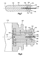
- another alternative exhaust spool 150 has a circular throttling edge 152 at the corner where its circular outer end surface 154 meets its cylindrical side surface 156.
- the spool 150 of Fig. 7 has an inner end surface 158 with a spherical contour.
- the spool 150 of Fig. 7 has a wider shaft 160 projecting coaxially from its outer end surface 154, which is correspondingly narrower than the outer end surface 104 shown in Fig. 5.
- Spacers 162 on the wider shaft 160 have the same outer diameter as the cylindrical side surface 156, and are likewise narrower than the spacers 114 shown in Fig. 5.
- the spacers 162 thus define intervening open regions 165 that are shaped as shallow channels extending axially over the shaft 160.
- a tappet or pintle 166 is press-fitted into the spool 150.
- the alternative spool 150 of Fig. 7 is installed in an alternative valve body 200, as shown in detail in the partial view of Fig. 8.
- This valve body 200 is shown to have multiple parts, including a spool guide insert 202.
- the insert 202 is a tubular part in which the spool 150 is received and supported for sliding movement back and forth along the longitudinal central axis 205.
- a cylindrical inner surface 206 of the insert 202 defines a bore 207 that communicates a control passage 209 with an exhaust passage 211.
- the cylindrical inner surface 206 has a circular edge 212 defining a throttling corner that is sized to function in the same manner as the throttling corner 80 described above.
- An armature 216 projects from a solenoid housing 218 into engagement with the inner end 158 of the spool 150.
- the rounded contour of the inner end 158 ensures that the armature 216 will make point contact at the center of the spool 150.
- the pintle 166 at the outer end of the spool 150 extends axially into engagement with a ball (not shown) that is seated under the supply pressure.
- the spacers 162 on the spool 150 are sized to slide in the bore 207 of Fig. 8 in the same manner that the spacers 114 on the spool 100 are sized to slide in the bore 77 of Fig. 6.
- the channels 165 between the spacers 162 serve as hydraulic fluid flow passages through the bore 207.
- the spacers 162 thus guide the circular throttling corner 152 on the spool 150 to move coaxially toward and past the circular throttling corner 212 on the valve body 200 when the armature 216 pushes the spool 150 from a fully closed position with the lowest control pressure, a shown in Fig. 8, toward and into a fully open position with the highest control pressure.
Landscapes
- Engineering & Computer Science (AREA)
- Physics & Mathematics (AREA)
- General Engineering & Computer Science (AREA)
- Fluid Mechanics (AREA)
- Mechanical Engineering (AREA)
- General Physics & Mathematics (AREA)
- Automation & Control Theory (AREA)
- Magnetically Actuated Valves (AREA)
- Control Of Transmission Device (AREA)
- Multiple-Way Valves (AREA)
Applications Claiming Priority (2)
| Application Number | Priority Date | Filing Date | Title |
|---|---|---|---|
| US81314606P | 2006-06-13 | 2006-06-13 | |
| US11/585,634 US20070284008A1 (en) | 2006-06-13 | 2006-10-24 | Pressure regulating valve |
Publications (2)
| Publication Number | Publication Date |
|---|---|
| EP1868057A2 true EP1868057A2 (fr) | 2007-12-19 |
| EP1868057A3 EP1868057A3 (fr) | 2009-06-03 |
Family
ID=38473941
Family Applications (1)
| Application Number | Title | Priority Date | Filing Date |
|---|---|---|---|
| EP20070011410 Withdrawn EP1868057A3 (fr) | 2006-06-13 | 2007-06-11 | Soupape de régulation de pression |
Country Status (4)
| Country | Link |
|---|---|
| US (1) | US20070284008A1 (fr) |
| EP (1) | EP1868057A3 (fr) |
| JP (1) | JP2007333211A (fr) |
| KR (1) | KR20070118960A (fr) |
Families Citing this family (9)
| Publication number | Priority date | Publication date | Assignee | Title |
|---|---|---|---|---|
| KR100890420B1 (ko) * | 2008-08-05 | 2009-03-26 | 주식회사 유니크 | 변속기용 솔레노이드 밸브 |
| KR100948508B1 (ko) * | 2009-12-15 | 2010-03-23 | 주식회사 유니크 | 가변 밸브 리프트 시스템용 오일 제어 밸브 |
| US8424567B2 (en) * | 2009-12-18 | 2013-04-23 | Cameron International Corporation | Bi-directional valve with cavity pressure relief |
| CN102181586B (zh) * | 2011-04-01 | 2013-02-06 | 扬州扬宝机械有限公司 | 板式熨平压花机的液压控制系统 |
| CN102400970B (zh) * | 2011-12-01 | 2014-11-26 | 宁波华液机器制造有限公司 | 溢流节流阀 |
| DE102013101038B3 (de) * | 2013-02-01 | 2014-04-03 | Pierburg Gmbh | Ventilvorrichtung für einen Hydraulikkreislauf sowie Ölpumpenregelanordnung |
| US9377124B2 (en) * | 2013-10-15 | 2016-06-28 | Continental Automotive Systems, Inc. | Normally low solenoid valve assembly |
| US9945492B2 (en) * | 2013-10-15 | 2018-04-17 | Continental Automotive Systems, Inc. | Normally high solenoid assembly |
| US20180372237A1 (en) * | 2017-06-22 | 2018-12-27 | Schaeffler Technologies AG & Co. KG | Normally closed fast-acting solenoid valve |
Family Cites Families (11)
| Publication number | Priority date | Publication date | Assignee | Title |
|---|---|---|---|---|
| DE3503785A1 (de) * | 1985-02-05 | 1986-08-07 | Rausch & Pausch, 8672 Selb | Magnetventil, insbesondere fuer hydraulische steuerungen |
| DE4337763A1 (de) * | 1993-11-05 | 1995-05-11 | Teves Gmbh Alfred | Druckregelventil |
| DE4345396C2 (de) * | 1993-11-26 | 2002-07-04 | Claas Kgaa Mbh | Hydraulisches Steuerventil |
| US5606992A (en) * | 1994-05-18 | 1997-03-04 | Coltec Industries Inc. | Pulse width modulated solenoid |
| US5738142A (en) * | 1996-08-09 | 1998-04-14 | Case Corporation | Pressure holding directional control valve |
| DE59807194D1 (de) * | 1997-04-18 | 2003-03-20 | Zahnradfabrik Friedrichshafen | Druckregelventil |
| DE19733660A1 (de) * | 1997-08-04 | 1999-02-25 | Bosch Gmbh Robert | Elektromagnetisches Druckregelventil |
| US6435213B2 (en) * | 1999-04-23 | 2002-08-20 | Visteon Global Technologies, Inc. | Solenoid operated hydraulic control valve |
| US6866063B2 (en) * | 2002-09-06 | 2005-03-15 | Delphi Technologies, Inc. | Low leak pressure control actuator |
| US6880570B2 (en) * | 2003-08-14 | 2005-04-19 | Delphi Technologies, Inc. | Vehicle actuator |
| US7165574B2 (en) * | 2003-09-03 | 2007-01-23 | Keihin Corporation | Solenoid valve with cylindrical valve guide for the spherical valve element at the pressure inlet |
-
2006
- 2006-10-24 US US11/585,634 patent/US20070284008A1/en not_active Abandoned
-
2007
- 2007-06-11 JP JP2007154365A patent/JP2007333211A/ja active Pending
- 2007-06-11 EP EP20070011410 patent/EP1868057A3/fr not_active Withdrawn
- 2007-06-11 KR KR1020070056637A patent/KR20070118960A/ko not_active Ceased
Also Published As
| Publication number | Publication date |
|---|---|
| US20070284008A1 (en) | 2007-12-13 |
| KR20070118960A (ko) | 2007-12-18 |
| EP1868057A3 (fr) | 2009-06-03 |
| JP2007333211A (ja) | 2007-12-27 |
Similar Documents
| Publication | Publication Date | Title |
|---|---|---|
| EP1868057A2 (fr) | Soupape de régulation de pression | |
| US6904937B2 (en) | Switchable fluid control valve system | |
| KR101557516B1 (ko) | 통합된 체크 밸브를 구비한 유압 제어 밸브 | |
| EP2495482A1 (fr) | Électrovanne | |
| US10161509B2 (en) | Hydraulic control device for an automatic transmission | |
| JPH0599367A (ja) | 二方向性カートリツジ弁 | |
| WO2012128797A2 (fr) | Soupape à champignon à commande par pilote électro-proportionnelle à compensation de pression | |
| CN101910570A (zh) | 用于顶置凸轮的具有多个摇臂的滑动枢转锁定机构 | |
| US20120112111A1 (en) | Pressure regulating valve, in particular for activating a clutch in a motor vehicle automatic transmission | |
| US20040129322A1 (en) | Pressure control valve for controlling two pressure load paths | |
| CN101680531A (zh) | 调节阀 | |
| JP7706308B2 (ja) | 圧力補償弁 | |
| WO2020054837A1 (fr) | Électrovanne linéaire | |
| JP2014518359A (ja) | 弁、特に圧力調整弁又は圧力制限弁 | |
| US7100753B1 (en) | Torque converter clutch apply valve | |
| CN100504698C (zh) | 压力调节阀 | |
| HK1106963A (en) | Pressure regulating valve | |
| JPH01134010A (ja) | 内燃機関の動弁装置 | |
| US8955533B2 (en) | Multiple pressure ratio valve assembly | |
| US7404292B2 (en) | Hydraulic system, in particular for motor vehicles | |
| JP4573561B2 (ja) | 容積型回転ポンプ | |
| CN217951303U (zh) | 一种紧凑型四位四通换挡控制阀 | |
| JPS61206862A (ja) | 無段可変伝動装置 | |
| JP3659702B2 (ja) | パワーステアリング装置 | |
| JP2003247656A (ja) | 電磁制御弁 |
Legal Events
| Date | Code | Title | Description |
|---|---|---|---|
| PUAI | Public reference made under article 153(3) epc to a published international application that has entered the european phase |
Free format text: ORIGINAL CODE: 0009012 |
|
| 17P | Request for examination filed |
Effective date: 20070611 |
|
| AK | Designated contracting states |
Kind code of ref document: A2 Designated state(s): AT BE BG CH CY CZ DE DK EE ES FI FR GB GR HU IE IS IT LI LT LU LV MC MT NL PL PT RO SE SI SK TR |
|
| AX | Request for extension of the european patent |
Extension state: AL BA HR MK YU |
|
| REG | Reference to a national code |
Ref country code: HK Ref legal event code: DE Ref document number: 1106963 Country of ref document: HK |
|
| PUAL | Search report despatched |
Free format text: ORIGINAL CODE: 0009013 |
|
| AK | Designated contracting states |
Kind code of ref document: A3 Designated state(s): AT BE BG CH CY CZ DE DK EE ES FI FR GB GR HU IE IS IT LI LT LU LV MC MT NL PL PT RO SE SI SK TR |
|
| AX | Request for extension of the european patent |
Extension state: AL BA HR MK RS |
|
| AKX | Designation fees paid | ||
| STAA | Information on the status of an ep patent application or granted ep patent |
Free format text: STATUS: THE APPLICATION IS DEEMED TO BE WITHDRAWN |
|
| 18D | Application deemed to be withdrawn |
Effective date: 20091204 |
|
| REG | Reference to a national code |
Ref country code: DE Ref legal event code: 8566 |
|
| REG | Reference to a national code |
Ref country code: HK Ref legal event code: WD Ref document number: 1106963 Country of ref document: HK |