EP1868710B1 - Rührvorrichtung und verfahren zur abwasserbehandlung - Google Patents
Rührvorrichtung und verfahren zur abwasserbehandlung Download PDFInfo
- Publication number
- EP1868710B1 EP1868710B1 EP06724030A EP06724030A EP1868710B1 EP 1868710 B1 EP1868710 B1 EP 1868710B1 EP 06724030 A EP06724030 A EP 06724030A EP 06724030 A EP06724030 A EP 06724030A EP 1868710 B1 EP1868710 B1 EP 1868710B1
- Authority
- EP
- European Patent Office
- Prior art keywords
- ribs
- agitating device
- agitating
- basin
- shaft
- Prior art date
- Legal status (The legal status is an assumption and is not a legal conclusion. Google has not performed a legal analysis and makes no representation as to the accuracy of the status listed.)
- Expired - Lifetime
Links
Images


Classifications
-
- C—CHEMISTRY; METALLURGY
- C02—TREATMENT OF WATER, WASTE WATER, SEWAGE, OR SLUDGE
- C02F—TREATMENT OF WATER, WASTE WATER, SEWAGE, OR SLUDGE
- C02F3/00—Biological treatment of water, waste water, or sewage
- C02F3/02—Aerobic processes
- C02F3/12—Activated sludge processes
- C02F3/1278—Provisions for mixing or aeration of the mixed liquor
- C02F3/1284—Mixing devices
-
- B—PERFORMING OPERATIONS; TRANSPORTING
- B01—PHYSICAL OR CHEMICAL PROCESSES OR APPARATUS IN GENERAL
- B01F—MIXING, e.g. DISSOLVING, EMULSIFYING OR DISPERSING
- B01F23/00—Mixing according to the phases to be mixed, e.g. dispersing or emulsifying
- B01F23/20—Mixing gases with liquids
- B01F23/23—Mixing gases with liquids by introducing gases into liquid media, e.g. for producing aerated liquids
- B01F23/234—Surface aerating
- B01F23/2342—Surface aerating with stirrers near to the liquid surface, e.g. partially immersed, for spraying the liquid in the gas or for sucking gas into the liquid, e.g. using stirrers rotating around a horizontal axis or using centrifugal force
- B01F23/23421—Surface aerating with stirrers near to the liquid surface, e.g. partially immersed, for spraying the liquid in the gas or for sucking gas into the liquid, e.g. using stirrers rotating around a horizontal axis or using centrifugal force the stirrers rotating about a vertical axis
-
- B—PERFORMING OPERATIONS; TRANSPORTING
- B01—PHYSICAL OR CHEMICAL PROCESSES OR APPARATUS IN GENERAL
- B01F—MIXING, e.g. DISSOLVING, EMULSIFYING OR DISPERSING
- B01F27/00—Mixers with rotary stirring devices in fixed receptacles; Kneaders
- B01F27/05—Stirrers
- B01F27/11—Stirrers characterised by the configuration of the stirrers
- B01F27/117—Stirrers provided with conical-shaped elements, e.g. funnel-shaped
- B01F27/1171—Stirrers provided with conical-shaped elements, e.g. funnel-shaped having holes in the surface
-
- Y—GENERAL TAGGING OF NEW TECHNOLOGICAL DEVELOPMENTS; GENERAL TAGGING OF CROSS-SECTIONAL TECHNOLOGIES SPANNING OVER SEVERAL SECTIONS OF THE IPC; TECHNICAL SUBJECTS COVERED BY FORMER USPC CROSS-REFERENCE ART COLLECTIONS [XRACs] AND DIGESTS
- Y02—TECHNOLOGIES OR APPLICATIONS FOR MITIGATION OR ADAPTATION AGAINST CLIMATE CHANGE
- Y02W—CLIMATE CHANGE MITIGATION TECHNOLOGIES RELATED TO WASTEWATER TREATMENT OR WASTE MANAGEMENT
- Y02W10/00—Technologies for wastewater treatment
- Y02W10/10—Biological treatment of water, waste water, or sewage
Definitions
- the invention relates to a stirring device according to the preamble of claim 1, it also relates to a method for wastewater treatment.
- a generic stirring device is for example from the DE 42 18 027 A1 as well as the DE 298 03 497 U1 , which discloses a stirring device according to the preamble of claim 1, known.
- the known stirring devices have a hyperboloid-like stirring body, on the upper side of which a plurality of ribs extending from the peripheral edge in the direction of a shaft are provided. A height of the ribs is either constant or decreases from the peripheral edge in the direction of the shaft.
- Such hyperboloidal stirring bodies have prevailed in particular in the field of wastewater treatment because of their good stirring properties. Nevertheless, a further increase in the efficiency of such stirring bodies would be desirable.
- the object of the invention is to provide a stirring device with improved efficiency. According to a further object of the invention, a method of wastewater treatment which is as efficient as possible should be specified.
- a first height of the ribs increases at least in sections from the peripheral edge of the stirring body in the direction of the shaft.
- a “height" of the ribs is understood to be the length of a normal reaching from an upper edge of the ribs to the surface of the hyperboloid-like stirring body.
- the height decreases in a direction extending from the circumferential rank in the direction of the first shaft portion and in a further from a first end of the first portion extending in the direction of the shaft second portion.
- the ribs may have a curvature in plan view of the top, which may be formed in particular hyperbolic. Ribs having the aforementioned features enable efficient transmission of the rotational energy of the stirring body to a liquid surrounding it.
- the stirring body has a plurality of openings provided in the vicinity of the shaft.
- the openings are expediently arranged regularly, preferably at the same radial distance.
- the proposed breakthroughs allow on the one hand an escape of gas bubbles possibly forming below the stirring body. But they also allow the formation of an axial, to the bottom of a basin, in which the stirring body protrudes directed flow. Such a flow contributes to the fact that possibly deposits forming below the stirring body, for example sand and the like, are removed.
- a plurality of further ribs extending in the direction of the peripheral edge are provided on an underside of the stirring body opposite the upper side.
- the further ribs can extend radially.
- a second height of the further ribs expediently decreases in a section running from a central region of the stirring body in the direction of the peripheral edge and in a fourth section extending further from the second end of the third section in the direction of the peripheral edge.
- the further ribs may each have a horizontal section for supporting on a stirring element stacked below for transport or storage purposes. The proposed further ribs generate a negative pressure during a rotation of the stirring body.
- the ribs expediently extend from the peripheral edge to near the shaft, ie their length extends essentially over the entire radial distance of the upper side.
- the further ribs expediently do not extend to the peripheral edge.
- Their radial extent is advantageously at most half as large as that of the ribs.
- an alternative object of the invention may be provided to increase the efficiency of a stirring device in which a hyperboloid-like stirring body is connected via a shaft with a drive means, wherein the stirring body has a plurality provided in the vicinity of the shaft openings, and wherein at an underside of the Rlick stresses more in the direction of the peripheral edge extending further ribs are provided.
- the stirring body has a plurality provided in the vicinity of the shaft openings, and wherein at an underside of the Rlick stresses more in the direction of the peripheral edge extending further ribs are provided.
- the stirring body is made together with the ribs and / or the other ribs in one piece, preferably made of a fiber-reinforced plastic. This facilitates the production and increases the stability of the proposed stirring body.
- conventional and well-controlled production techniques can be used.
- a wastewater treatment device is provided with at least one stirring device according to the invention, wherein the stirring element accommodated on the shaft protrudes into a basin and the drive device is received on a frame outside the basin.
- the frame can be a bridge-like frame extending from the edge of the pelvis in the direction of the pelvis.
- the frame can be supported on a floor of the basin.
- the stirring body it is also possible for the stirring body to be accommodated on a tower-like frame supported completely on the bottom of the basin, wherein in turn a drive device is accommodated outside the basin.
- the stirring body by means of drive means to drive, which is received as a dipping device below a mirror of the liquid to be stirred on a frame.
- a ventilation device is provided.
- a ventilation device allows a particularly efficient degradation of pollutants in wastewater, especially in a wastewater treatment.
- These may be pipes or hoses laid at the bottom of the tank, which are provided with openings, slots and the like for ventilation.
- the ventilation device can also be part of the stirring device. For example, the air may be forced into the liquid through a rack extending into the basin or through the shaft of the stirring device.
- the steps lit. c) and d) can be repeated several times alternately. It is also possible to step lit. d) before step lit. c) execute.
- the proposed method allows a particularly efficient removal of pollutants contained in the wastewater.
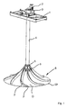
- Fig. 1 shows a stirring device in which a frame 1 shown in sections, a drive device 2 is received with a gear 3.
- a shaft 4 which z. B. consists of a tube made of fiber-reinforced plastic.
- a shaft 4 which z. B. consists of a tube made of fiber-reinforced plastic.
- agitator 6 is attached at a provided at the end of the shaft 4 flange 5 .
- the stirring body 6 has a hyperboloid-like shape.
- On its top O ribs 7 are provided.
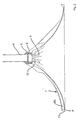
- a cross-sectional area F of the ribs 7 is formed asymmetrically with a steeply rising flank and a gently sloping flank.
- the ribs 7 extend from a peripheral edge Ur of the stirring body 6 in the direction of the shaft 4.
- the ribs 7 are curved, preferably hyperboloid-like.
- a steep flank of the ribs 7 forming profile is in Fig. 5 designated by the reference F1, a gently sloping edge with the reference F2.
- Fig. 1 to 5 are marked with the reference numeral 8 breakthroughs, which are provided in the vicinity of the shaft 4 and in the vicinity of a mounting portion 9 of the stirring body 6.
- the openings 8 are arranged between the ribs 7. They have an elongated or slit-like shape and extend substantially parallel to the ribs 7.
- a first height h1 increases steadily in a first section A1 extending from the peripheral edge Ur in the direction of the fastening section 9.
- the first height h1 is at a first end E1 of the first section A1 maximum.
- the first height h1 steadily decreases in a second section A2 extending from the first end E1 in the direction of the fastening section 9. It is zero near the attachment section 9.
- a ratio of the lengths of sections A1 / A2 may be in the range of 0.5 to 1.5.
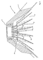
- Fig. 6 shows a perspective view of a partially broken stirrer 6.
- a bottom U further ribs 10 are provided, which extend from the attachment portion 9 and a central portion of the stirring body 6 radially in the direction of (not visible here) peripheral edge Ur.
- a second height h2 of the further ribs 10 also increases in a third section A3 which extends from the attachment section 9 in the direction of the peripheral edge Ur.
- the second height h2 is maximum. It steadily decreases to zero in a fourth section A4 extending from the further end E2 in the direction of the peripheral edge Ur.
- the further ribs 10 have a horizontal section Ah, which serves a support surface for stacking the stirring body 6 on the attachment section 9 of a further stirring body located therebelow.
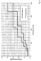
- the advantageous mode of operation of the stirring device is particularly based on the in Fig. 7 shown clearly comparative results.
- the measured values marked with a circle have been obtained with a stirring body on whose upper sides ribs with a constant first rib height have been provided.
- the measured values marked with a cross have been achieved with a further stirring body, on the upper side of which ribs with a constant second rib height have been attached.
- the second rib height has been greater than the first rib height.
- the measurements marked with squares have been achieved with a stirring body according to the invention.
- Comparatively illustrated measured values impressively show the improved efficiency of the agitator 6 according to the invention.
- a sol velocity at the bottom of a tank filled with a liquid is up to 30% higher than the sol velocities achievable with conventional agitating bodies.
- Fig. 8 the power input of a conventional stirring element (Generation 5) is plotted against the pelvic volume in comparison to a stirring element (Generation 6) according to the invention.
- the conventional stirrer body (Generation 5) was a stirring body, as it is known from US Pat DE 298 03 497 U1 is known. How out Fig. 8 it can be seen, with the stirrer according to the invention (Generation 6), for example, with a tank volume of 1000 m 3, the power input can be reduced by 40% compared to the conventional stirrer body (Generation 5).
- Fig. 9 shows the rated motor power for the conventional agitator (Generation 5) according to the DE 298 03 497 U1 relative to the stirrer according to the invention (Generation 6) above the pelvic volume.
- the rated motor power to drive the compared stirring body at a pool volume of 1000 m 3 of about 2.2 kW in the conventional agitator (generation 5) can be reduced to 1.5 kW in a stirring body (generation 6) according to the invention. This corresponds to a saving of more than 30% of the power to be installed, ie the energy to be provided.
Landscapes
- Chemical & Material Sciences (AREA)
- Chemical Kinetics & Catalysis (AREA)
- Life Sciences & Earth Sciences (AREA)
- Engineering & Computer Science (AREA)
- Microbiology (AREA)
- Hydrology & Water Resources (AREA)
- Biodiversity & Conservation Biology (AREA)
- Environmental & Geological Engineering (AREA)
- Water Supply & Treatment (AREA)
- Organic Chemistry (AREA)
- Mixers Of The Rotary Stirring Type (AREA)
- Physical Water Treatments (AREA)
- Treatment Of Sludge (AREA)
- Excavating Of Shafts Or Tunnels (AREA)
Priority Applications (1)
| Application Number | Priority Date | Filing Date | Title |
|---|---|---|---|
| PL06724030T PL1868710T3 (pl) | 2005-04-12 | 2006-04-05 | Mieszadło i sposób obróbki ścieków |
Applications Claiming Priority (2)
| Application Number | Priority Date | Filing Date | Title |
|---|---|---|---|
| DE102005016948A DE102005016948B3 (de) | 2005-04-12 | 2005-04-12 | Rührvorrichtung und Verfahren zur Abwasserbehandlung |
| PCT/EP2006/003077 WO2006108538A1 (de) | 2005-04-12 | 2006-04-05 | Rührvorrichtung und verfahren zur abwasserbehandlung |
Publications (2)
| Publication Number | Publication Date |
|---|---|
| EP1868710A1 EP1868710A1 (de) | 2007-12-26 |
| EP1868710B1 true EP1868710B1 (de) | 2008-09-17 |
Family
ID=36603511
Family Applications (1)
| Application Number | Title | Priority Date | Filing Date |
|---|---|---|---|
| EP06724030A Expired - Lifetime EP1868710B1 (de) | 2005-04-12 | 2006-04-05 | Rührvorrichtung und verfahren zur abwasserbehandlung |
Country Status (10)
| Country | Link |
|---|---|
| US (1) | US7784769B2 (pl) |
| EP (1) | EP1868710B1 (pl) |
| CN (1) | CN100571853C (pl) |
| AT (1) | ATE408449T1 (pl) |
| CA (1) | CA2603984C (pl) |
| DE (2) | DE102005016948B3 (pl) |
| DK (1) | DK1868710T3 (pl) |
| ES (1) | ES2313634T3 (pl) |
| PL (1) | PL1868710T3 (pl) |
| WO (1) | WO2006108538A1 (pl) |
Families Citing this family (21)
| Publication number | Priority date | Publication date | Assignee | Title |
|---|---|---|---|---|
| US7954789B2 (en) * | 2007-01-03 | 2011-06-07 | Jet, Inc. | Composite shaft and self-centering coupling |
| US7954790B2 (en) * | 2007-01-03 | 2011-06-07 | Jet, Inc. | Composite shaft aspirator assembly |
| DE102007037586B3 (de) * | 2007-08-09 | 2008-09-18 | Invent Umwelt- Und Verfahrenstechnik Ag | Rührvorrichtung für Belebtschlämme |
| DK2175972T3 (da) * | 2007-08-09 | 2012-08-27 | Invent Umwelt & Verfahrenstech | Røreindretning til aktiveret slam |
| EP2175973B1 (de) * | 2007-08-09 | 2011-05-25 | INVENT Umwelt- und Verfahrenstechnik AG | Rührvorrichtung für belebtschlämme |
| DE102009045032A1 (de) * | 2009-09-25 | 2011-03-31 | Invent Umwelt-Und Verfahrenstechnik Ag | Verfahren und Vorrichtung zur biologischen Reinigung von Abwasser |
| DE102010000730B4 (de) * | 2010-01-07 | 2011-12-15 | Invent Umwelt- Und Verfahrenstechnik Ag | Vertikalrührwerk für in einem Klärbecken aufgenommenes Abwasser |
| WO2013082717A1 (en) * | 2011-12-06 | 2013-06-13 | Bachellier Carl Roy | Improved impeller apparatus and dispersion method |
| DE102013225662A1 (de) * | 2013-12-11 | 2015-06-11 | Invent Umwelt- Und Verfahrenstechnik Ag | Rührkörper zum Umwälzen von in einem Becken aufgenommenem Abwasser und Vorrichtung |
| DE102013225659A1 (de) | 2013-12-11 | 2015-06-11 | Invent Umwelt- Und Verfahrenstechnik Ag | Vorrichtung zum Umwälzen einer in einem Behälter aufgenommenen Flüssigkeit |
| DE102013225658A1 (de) * | 2013-12-11 | 2015-06-11 | Invent Umwelt- Und Verfahrenstechnik Ag | Rührkörper und Rührvorrichtung zum Erzeugen einer Strömung in einem Abwasserbehandlungsbecken |
| US9863423B2 (en) | 2014-04-14 | 2018-01-09 | Enevor Inc. | Conical impeller and applications thereof |
| US10173184B2 (en) * | 2015-03-25 | 2019-01-08 | Schlumberger Technology Corporation | Blender for mixing and pumping solids and fluids and method of use thereof |
| CN106732005B (zh) * | 2017-01-18 | 2023-10-27 | 北京首创环境科技有限公司 | 搅拌设备 |
| CN106994307A (zh) * | 2017-04-07 | 2017-08-01 | 南京中德环保设备制造有限公司 | 一种立式搅拌机高效搅拌涡轮 |
| RU2683078C1 (ru) * | 2018-06-06 | 2019-03-26 | Непубличное акционерное общество "Астерион" | Перемешивающее устройство |
| DE102019101416B4 (de) * | 2018-12-03 | 2020-07-16 | Invent Umwelt- Und Verfahrenstechnik Ag | Hyperboloid-Rührkörper zum Umwälzen von Flüssigkeiten sowie Rühr- und Begasungseinrichtung |
| JP7237561B2 (ja) * | 2018-12-19 | 2023-03-13 | プライミクス株式会社 | 攪拌羽根および攪拌装置 |
| CN109824104A (zh) * | 2019-04-10 | 2019-05-31 | 尚川(北京)水务有限公司 | 一种双曲面搅拌器 |
| DE102019111492A1 (de) * | 2019-05-03 | 2020-11-05 | Invent Umwelt-Und Verfahrenstechnik Ag | Propeller und Rührwerk zum Umwälzen von Abwasser in einem Klärbecken |
| MX388755B (es) * | 2019-11-22 | 2025-03-20 | Julian Martinez Fonseca | Equipo de gasificación, bombeo y mezclado de fluidos. |
Family Cites Families (6)
| Publication number | Priority date | Publication date | Assignee | Title |
|---|---|---|---|---|
| SU1007714A1 (ru) | 1974-07-10 | 1983-03-30 | Dmitriev Igor A | Устройство дл перемешивани компонентов |
| DE4218027A1 (de) * | 1991-05-30 | 1992-12-03 | Marcus Dipl Ing Hoefken | Hyperboloid-ruehr- und begasungssystem zum ruehren, mischen und begasen in ein- oder mehrphasigen fluiden |
| DE29803497U1 (de) * | 1998-02-27 | 1999-06-24 | Invent Umwelt Und Verfahrenste | Rührwerksanordnung |
| DE19826098C2 (de) | 1998-06-12 | 2002-03-14 | Franz Durst | Rührvorrichtung |
| CN2493283Y (zh) * | 2001-06-29 | 2002-05-29 | 诸暨市宏宇环保设备有限公司 | 立式环流搅拌机 |
| CN2521217Y (zh) * | 2001-12-28 | 2002-11-20 | 山东双轮集团股份有限公司 | 污水消化池搅拌器 |
-
2005
- 2005-04-12 DE DE102005016948A patent/DE102005016948B3/de not_active Expired - Fee Related
-
2006
- 2006-04-05 DE DE502006001605T patent/DE502006001605D1/de not_active Expired - Lifetime
- 2006-04-05 EP EP06724030A patent/EP1868710B1/de not_active Expired - Lifetime
- 2006-04-05 AT AT06724030T patent/ATE408449T1/de active
- 2006-04-05 ES ES06724030T patent/ES2313634T3/es not_active Expired - Lifetime
- 2006-04-05 DK DK06724030T patent/DK1868710T3/da active
- 2006-04-05 PL PL06724030T patent/PL1868710T3/pl unknown
- 2006-04-05 US US11/886,950 patent/US7784769B2/en active Active
- 2006-04-05 WO PCT/EP2006/003077 patent/WO2006108538A1/de not_active Ceased
- 2006-04-05 CA CA2603984A patent/CA2603984C/en not_active Expired - Lifetime
- 2006-04-05 CN CNB2006800116088A patent/CN100571853C/zh not_active Expired - Lifetime
Also Published As
| Publication number | Publication date |
|---|---|
| CN101155626A (zh) | 2008-04-02 |
| PL1868710T3 (pl) | 2009-03-31 |
| CA2603984A1 (en) | 2006-10-19 |
| DE502006001605D1 (de) | 2008-10-30 |
| ATE408449T1 (de) | 2008-10-15 |
| WO2006108538A1 (de) | 2006-10-19 |
| ES2313634T3 (es) | 2009-03-01 |
| DE102005016948B3 (de) | 2007-01-04 |
| US7784769B2 (en) | 2010-08-31 |
| CN100571853C (zh) | 2009-12-23 |
| CA2603984C (en) | 2010-07-13 |
| EP1868710A1 (de) | 2007-12-26 |
| US20090127213A1 (en) | 2009-05-21 |
| DK1868710T3 (da) | 2009-01-12 |
Similar Documents
| Publication | Publication Date | Title |
|---|---|---|
| EP1868710B1 (de) | Rührvorrichtung und verfahren zur abwasserbehandlung | |
| DE2461032C3 (de) | Vorrichtung zum Begasen und Umwälzen von z.B. wäßrigen Flüssigkeiten | |
| DE3886420T2 (de) | Behälter für agglutinierungsreaktionen. | |
| EP2613871B1 (de) | Rührwerk | |
| DE3126527A1 (de) | "einrichtung, die dazu geeignet ist, ein gas mit einer fluessigkeit und umgekehrt zu mischen oder eine fluesigkeit zu entgasen" | |
| DE69608694T2 (de) | Tauchbarer mischrührer | |
| DE69932115T2 (de) | Rührwerk mit senkrechter Achse | |
| EP0017064A1 (de) | Vorrichtung zur Belüftung von Abwässern oder Abwässerschlämmen | |
| EP2125180A1 (de) | Horizontalrührwerk und verfahren zum erzeugen einer strömung in einem klärbecken mit dem horizontalrührwerk | |
| WO2009018915A1 (de) | Rührvorrichtung für belebtschlämme | |
| WO2007128467A1 (de) | Reaktor mit filterplattenstapel | |
| CH690835A5 (de) | Rührwerk zum Anregen einer Güllen-Zirkulation in einem Güllenkasten. | |
| EP0564935A1 (de) | Kläreinrichtung für Abwässer | |
| EP2480504B1 (de) | Verfahren und vorrichtung zur biologischen reinigung von abwasser | |
| DE2644925C3 (de) | Vorrichtung zum Behändem von Flüssigkeiten, insbesondere Abwasser | |
| DE2407409B2 (de) | Schwimmfähige Vorrichtung zum Beseitigen von auf einer Wasseroberfläche schwimmenden Verunreinigungen | |
| EP2828210B1 (de) | Anordnung und verfahren zum erzeugen einer strömung in einem abwasserbehandlungsbecken | |
| DE1963614A1 (de) | Einrichtung zur Begasung von Fluessigkeiten | |
| DE2943335C2 (pl) | ||
| CH666020A5 (de) | Oberflaechenbelueftungskreisel sowie ein einen solchen enthaltendes abwasserbelueftungsbecken. | |
| DE102019111489A1 (de) | Abwasserreinigungsvorrichtung und Verfahren zum Reinigen von Abwasser | |
| DE2349218B1 (de) | Klaeranlage zum biologischen Reinigen von Abwasser | |
| WO2020030596A1 (de) | Tauchrührvorrichtung zum umwälzen von trinkwasser | |
| DE29819704U1 (de) | Begasungsvorrichtung für Flüssigkeiten | |
| DE3039423C2 (de) | Verfahren zur biologischen Reinigung von Abwasser |
Legal Events
| Date | Code | Title | Description |
|---|---|---|---|
| PUAI | Public reference made under article 153(3) epc to a published international application that has entered the european phase |
Free format text: ORIGINAL CODE: 0009012 |
|
| 17P | Request for examination filed |
Effective date: 20070921 |
|
| AK | Designated contracting states |
Kind code of ref document: A1 Designated state(s): AT BE BG CH CY CZ DE DK EE ES FI FR GB GR HU IE IS IT LI LT LU LV MC NL PL PT RO SE SI SK TR |
|
| GRAP | Despatch of communication of intention to grant a patent |
Free format text: ORIGINAL CODE: EPIDOSNIGR1 |
|
| DAX | Request for extension of the european patent (deleted) | ||
| GRAS | Grant fee paid |
Free format text: ORIGINAL CODE: EPIDOSNIGR3 |
|
| GRAA | (expected) grant |
Free format text: ORIGINAL CODE: 0009210 |
|
| AK | Designated contracting states |
Kind code of ref document: B1 Designated state(s): AT BE BG CH CY CZ DE DK EE ES FI FR GB GR HU IE IS IT LI LT LU LV MC NL PL PT RO SE SI SK TR |
|
| REG | Reference to a national code |
Ref country code: GB Ref legal event code: FG4D Free format text: NOT ENGLISH |
|
| REG | Reference to a national code |
Ref country code: CH Ref legal event code: EP |
|
| REG | Reference to a national code |
Ref country code: IE Ref legal event code: FG4D Free format text: LANGUAGE OF EP DOCUMENT: GERMAN |
|
| REF | Corresponds to: |
Ref document number: 502006001605 Country of ref document: DE Date of ref document: 20081030 Kind code of ref document: P |
|
| REG | Reference to a national code |
Ref country code: CH Ref legal event code: NV Representative=s name: GLN GRESSET & LAESSER NEUCHATEL CABINET DE CONSEIL |
|
| REG | Reference to a national code |
Ref country code: DK Ref legal event code: T3 |
|
| REG | Reference to a national code |
Ref country code: SE Ref legal event code: TRGR |
|
| PG25 | Lapsed in a contracting state [announced via postgrant information from national office to epo] |
Ref country code: LT Free format text: LAPSE BECAUSE OF FAILURE TO SUBMIT A TRANSLATION OF THE DESCRIPTION OR TO PAY THE FEE WITHIN THE PRESCRIBED TIME-LIMIT Effective date: 20080917 |
|
| PG25 | Lapsed in a contracting state [announced via postgrant information from national office to epo] |
Ref country code: LV Free format text: LAPSE BECAUSE OF FAILURE TO SUBMIT A TRANSLATION OF THE DESCRIPTION OR TO PAY THE FEE WITHIN THE PRESCRIBED TIME-LIMIT Effective date: 20080917 Ref country code: SI Free format text: LAPSE BECAUSE OF FAILURE TO SUBMIT A TRANSLATION OF THE DESCRIPTION OR TO PAY THE FEE WITHIN THE PRESCRIBED TIME-LIMIT Effective date: 20080917 |
|
| REG | Reference to a national code |
Ref country code: ES Ref legal event code: FG2A Ref document number: 2313634 Country of ref document: ES Kind code of ref document: T3 |
|
| REG | Reference to a national code |
Ref country code: PL Ref legal event code: T3 |
|
| PG25 | Lapsed in a contracting state [announced via postgrant information from national office to epo] |
Ref country code: BG Free format text: LAPSE BECAUSE OF FAILURE TO SUBMIT A TRANSLATION OF THE DESCRIPTION OR TO PAY THE FEE WITHIN THE PRESCRIBED TIME-LIMIT Effective date: 20081217 |
|
| PG25 | Lapsed in a contracting state [announced via postgrant information from national office to epo] |
Ref country code: RO Free format text: LAPSE BECAUSE OF FAILURE TO SUBMIT A TRANSLATION OF THE DESCRIPTION OR TO PAY THE FEE WITHIN THE PRESCRIBED TIME-LIMIT Effective date: 20080917 Ref country code: IS Free format text: LAPSE BECAUSE OF FAILURE TO SUBMIT A TRANSLATION OF THE DESCRIPTION OR TO PAY THE FEE WITHIN THE PRESCRIBED TIME-LIMIT Effective date: 20090117 Ref country code: PT Free format text: LAPSE BECAUSE OF FAILURE TO SUBMIT A TRANSLATION OF THE DESCRIPTION OR TO PAY THE FEE WITHIN THE PRESCRIBED TIME-LIMIT Effective date: 20090217 Ref country code: SK Free format text: LAPSE BECAUSE OF FAILURE TO SUBMIT A TRANSLATION OF THE DESCRIPTION OR TO PAY THE FEE WITHIN THE PRESCRIBED TIME-LIMIT Effective date: 20080917 |
|
| PLBE | No opposition filed within time limit |
Free format text: ORIGINAL CODE: 0009261 |
|
| STAA | Information on the status of an ep patent application or granted ep patent |
Free format text: STATUS: NO OPPOSITION FILED WITHIN TIME LIMIT |
|
| PG25 | Lapsed in a contracting state [announced via postgrant information from national office to epo] |
Ref country code: EE Free format text: LAPSE BECAUSE OF FAILURE TO SUBMIT A TRANSLATION OF THE DESCRIPTION OR TO PAY THE FEE WITHIN THE PRESCRIBED TIME-LIMIT Effective date: 20080917 |
|
| 26N | No opposition filed |
Effective date: 20090618 |
|
| REG | Reference to a national code |
Ref country code: HU Ref legal event code: AG4A Ref document number: E006676 Country of ref document: HU |
|
| PG25 | Lapsed in a contracting state [announced via postgrant information from national office to epo] |
Ref country code: MC Free format text: LAPSE BECAUSE OF NON-PAYMENT OF DUE FEES Effective date: 20090430 |
|
| PG25 | Lapsed in a contracting state [announced via postgrant information from national office to epo] |
Ref country code: GR Free format text: LAPSE BECAUSE OF FAILURE TO SUBMIT A TRANSLATION OF THE DESCRIPTION OR TO PAY THE FEE WITHIN THE PRESCRIBED TIME-LIMIT Effective date: 20081218 |
|
| PG25 | Lapsed in a contracting state [announced via postgrant information from national office to epo] |
Ref country code: LU Free format text: LAPSE BECAUSE OF NON-PAYMENT OF DUE FEES Effective date: 20090405 |
|
| PG25 | Lapsed in a contracting state [announced via postgrant information from national office to epo] |
Ref country code: TR Free format text: LAPSE BECAUSE OF FAILURE TO SUBMIT A TRANSLATION OF THE DESCRIPTION OR TO PAY THE FEE WITHIN THE PRESCRIBED TIME-LIMIT Effective date: 20080917 |
|
| PG25 | Lapsed in a contracting state [announced via postgrant information from national office to epo] |
Ref country code: CY Free format text: LAPSE BECAUSE OF FAILURE TO SUBMIT A TRANSLATION OF THE DESCRIPTION OR TO PAY THE FEE WITHIN THE PRESCRIBED TIME-LIMIT Effective date: 20080917 |
|
| REG | Reference to a national code |
Ref country code: CH Ref legal event code: PFA Owner name: INVENT UMWELT- UND VERFAHRENSTECHNIK AG, DE Free format text: FORMER OWNER: INVENT UMWELT- UND VERFAHRENSTECHNIK AG, DE |
|
| REG | Reference to a national code |
Ref country code: FR Ref legal event code: PLFP Year of fee payment: 11 |
|
| REG | Reference to a national code |
Ref country code: CH Ref legal event code: PFA Owner name: INVENT UMWELT- UND VERFAHRENSTECHNIK AG, DE Free format text: FORMER OWNER: INVENT UMWELT- UND VERFAHRENSTECHNIK AG, DE |
|
| REG | Reference to a national code |
Ref country code: FR Ref legal event code: PLFP Year of fee payment: 12 |
|
| REG | Reference to a national code |
Ref country code: FR Ref legal event code: PLFP Year of fee payment: 13 |
|
| REG | Reference to a national code |
Ref country code: CH Ref legal event code: NV Representative=s name: BOVARD SA NEUCHATEL CONSEILS EN PROPRIETE INTE, CH |
|
| REG | Reference to a national code |
Ref country code: DE Ref legal event code: R079 Ref document number: 502006001605 Country of ref document: DE Free format text: PREVIOUS MAIN CLASS: B01F0003040000 Ipc: B01F0023200000 |
|
| PGFP | Annual fee paid to national office [announced via postgrant information from national office to epo] |
Ref country code: SE Payment date: 20250311 Year of fee payment: 20 |
|
| PGFP | Annual fee paid to national office [announced via postgrant information from national office to epo] |
Ref country code: PL Payment date: 20250327 Year of fee payment: 20 Ref country code: CZ Payment date: 20250321 Year of fee payment: 20 |
|
| PGFP | Annual fee paid to national office [announced via postgrant information from national office to epo] |
Ref country code: NL Payment date: 20250422 Year of fee payment: 20 |
|
| PGFP | Annual fee paid to national office [announced via postgrant information from national office to epo] |
Ref country code: FI Payment date: 20250417 Year of fee payment: 20 |
|
| PGFP | Annual fee paid to national office [announced via postgrant information from national office to epo] |
Ref country code: DE Payment date: 20250417 Year of fee payment: 20 |
|
| PGFP | Annual fee paid to national office [announced via postgrant information from national office to epo] |
Ref country code: GB Payment date: 20250423 Year of fee payment: 20 Ref country code: ES Payment date: 20250519 Year of fee payment: 20 Ref country code: DK Payment date: 20250423 Year of fee payment: 20 |
|
| PGFP | Annual fee paid to national office [announced via postgrant information from national office to epo] |
Ref country code: HU Payment date: 20250331 Year of fee payment: 20 |
|
| PGFP | Annual fee paid to national office [announced via postgrant information from national office to epo] |
Ref country code: BE Payment date: 20250422 Year of fee payment: 20 Ref country code: IT Payment date: 20250430 Year of fee payment: 20 |
|
| PGFP | Annual fee paid to national office [announced via postgrant information from national office to epo] |
Ref country code: FR Payment date: 20250425 Year of fee payment: 20 |
|
| PGFP | Annual fee paid to national office [announced via postgrant information from national office to epo] |
Ref country code: CH Payment date: 20250501 Year of fee payment: 20 |
|
| PGFP | Annual fee paid to national office [announced via postgrant information from national office to epo] |
Ref country code: AT Payment date: 20250416 Year of fee payment: 20 |
|
| PGFP | Annual fee paid to national office [announced via postgrant information from national office to epo] |
Ref country code: IE Payment date: 20250428 Year of fee payment: 20 |
|
| REG | Reference to a national code |
Ref country code: CH Ref legal event code: R18 Free format text: ST27 STATUS EVENT CODE: U-0-0-R10-R18 (AS PROVIDED BY THE NATIONAL OFFICE) Effective date: 20260209 |
|
| REG | Reference to a national code |
Ref country code: CH Ref legal event code: R18 Free format text: ST27 STATUS EVENT CODE: U-0-0-R10-R18 (AS PROVIDED BY THE NATIONAL OFFICE) Effective date: 20260320 |
|
| REG | Reference to a national code |
Ref country code: CH Ref legal event code: H14 Free format text: ST27 STATUS EVENT CODE: U-0-0-H10-H14 (AS PROVIDED BY THE NATIONAL OFFICE) Effective date: 20260405 Ref country code: DE Ref legal event code: R071 Ref document number: 502006001605 Country of ref document: DE |
|
| REG | Reference to a national code |
Ref country code: DK Ref legal event code: EUP Expiry date: 20260405 |
|
| REG | Reference to a national code |
Ref country code: NL Ref legal event code: MK Effective date: 20260404 |