EP1873403B1 - Befestigungsvorrichtung mit Schwenkbasis - Google Patents
Befestigungsvorrichtung mit Schwenkbasis Download PDFInfo
- Publication number
- EP1873403B1 EP1873403B1 EP07012461A EP07012461A EP1873403B1 EP 1873403 B1 EP1873403 B1 EP 1873403B1 EP 07012461 A EP07012461 A EP 07012461A EP 07012461 A EP07012461 A EP 07012461A EP 1873403 B1 EP1873403 B1 EP 1873403B1
- Authority
- EP
- European Patent Office
- Prior art keywords
- fastening
- housing
- fastening device
- base
- mounting
- Prior art date
- Legal status (The legal status is an assumption and is not a legal conclusion. Google has not performed a legal analysis and makes no representation as to the accuracy of the status listed.)
- Active
Links
Images


Classifications
-
- F—MECHANICAL ENGINEERING; LIGHTING; HEATING; WEAPONS; BLASTING
- F21—LIGHTING
- F21V—FUNCTIONAL FEATURES OR DETAILS OF LIGHTING DEVICES OR SYSTEMS THEREOF; STRUCTURAL COMBINATIONS OF LIGHTING DEVICES WITH OTHER ARTICLES, NOT OTHERWISE PROVIDED FOR
- F21V21/00—Supporting, suspending, or attaching arrangements for lighting devices; Hand grips
- F21V21/02—Wall, ceiling, or floor bases; Fixing pendants or arms to the bases
-
- A—HUMAN NECESSITIES
- A47—FURNITURE; DOMESTIC ARTICLES OR APPLIANCES; COFFEE MILLS; SPICE MILLS; SUCTION CLEANERS IN GENERAL
- A47B—TABLES; DESKS; OFFICE FURNITURE; CABINETS; DRAWERS; GENERAL DETAILS OF FURNITURE
- A47B2220/00—General furniture construction, e.g. fittings
- A47B2220/0075—Lighting
- A47B2220/0077—Lighting for furniture, e.g. cupboards and racks
-
- F—MECHANICAL ENGINEERING; LIGHTING; HEATING; WEAPONS; BLASTING
- F21—LIGHTING
- F21W—INDEXING SCHEME ASSOCIATED WITH SUBCLASSES F21K, F21L, F21S and F21V, RELATING TO USES OR APPLICATIONS OF LIGHTING DEVICES OR SYSTEMS
- F21W2131/00—Use or application of lighting devices or systems not provided for in codes F21W2102/00-F21W2121/00
- F21W2131/30—Lighting for domestic or personal use
- F21W2131/301—Lighting for domestic or personal use for furniture
Definitions
- the invention relates to a fastening device for a housing, in particular lamp housing, with at least two terminal device receptacles, wherein the terminal device receptacles are each arranged to receive a spatially positioning fastener on a pivotally mounted on the housing pivot base.
- the technical field of the invention relates in particular to the attachment of attachments to technical equipment, such as lights, which are used for lighting technical equipment.
- fastening devices of this type are used for fastening luminaires in cabinets or on shelves formed from or including horizontal and vertical profiles. If profiles are used as a mounting base for these housings, the profiles are often designed as a perforated grid profile with a defined hole spacing. The installation of this housing should usually be as fast and easy as possible, and the fastening technology must be easily adaptable to the particular technical conditions.
- fastening devices of this type such as screw, magnetic holding connections, plug or snap-in connections.
- the known fastening devices allow a housing mounting in only one mounting plane, since the fastening device is fixed in its relative position to the housing.
- a recessed ceiling light is known in which lever-shaped fastening means are pivotally mounted on a housing of the ceiling light. By operating a cable, the levers can be transferred to a mounting configuration superior to the outer housing dimensions.
- the US 1,045,859 describes a ceiling light, in which a housing of the recessed ceiling light can be fixed by means of a fastening device to components of a ceiling.
- the fastening device comprises two connector receptacles, which are each arranged on a pivotally mounted on the housing pivot base. At the Stanford Sawsmethodn each a spatially positionable fastening device is formed. By tightening a respective screw forming the pivot base, the fastening devices are fixed in their position.
- the object of the invention is to propose a fastening device that allows attachment of the housing in different mounting levels or mounting configurations.
- the housing fastening device has at least two connector receptacles, the connector receptacles each being arranged to receive a spatially positioning fastener on a pivot base pivotally mounted on the housing, and wherein the fastener is longitudinally displaceable with the connector receptacles.
- the spatially positioning fastener is used to change the housing positioning in a mounting plane and the connection of the housing with a mounting base. By pivotably mounted on the housing pivot base, the mounting of the housing in spatially different mounting configurations in conjunction with the respectively suitable fastening devices is possible.
- the fastening means may be formed as fastening tabs with a mounting hole for producing a bolt connection with a mounting base.
- fastening straps With such fastening straps, a screw, Raststatt- or rivet connection can be easily made with a mounting base.
- the fastening means may be formed as fastening tabs with a fastening projection for engagement in a mounting base. This allows the insertion or engagement of the fastening tabs in through holes of a mounting base and thus a positive fastening of the housing on the mounting base.
- connection device receptacles of the fastening device for receiving a fastening strap can have a guide receptacle for the longitudinally displaceable arrangement of the fastening strap. This allows the alignment of axially spaced apart mounting tabs to a predetermined hole spacing for screwing with or for engagement in a hole grid profile.
- the guide receptacle is provided with a raster device for relative positioning of the fastening lug.
- a raster device for relative positioning of the fastening lug.
- the housing is provided in each case at its axial ends with a swivel base for swiveling the fastening devices into a fastening configuration which projects axially beyond the outer housing dimensions.
- the housing can thus, each with a formed on the pivot base mounting tab, between two mutually parallel hole profiles, such as in a cabinet with 19-inch housing receptacles, are arranged.
- the fastening tabs can be pivoted such that they each engage in a passage opening in the perforated grid profile and by pivoting in an axial position along the housing are positively inserted into the through holes of the hole pattern grid.
- the housing can thus be mounted between two perforated grid profiles without additional tools and accessories.
- the swivel base is provided with a raster device for relative positioning of the fastening device, by fixing the swivel base to the housing a fixing of the fastening configuration, e.g. of the housing between two perforated grid profiles can be achieved. Furthermore, it proves to be advantageous if the pivot base engages in three different positions on the housing. Thus, the pivot base can be fixed in a storage position, in a mounting position and in an end position. This significantly facilitates the insertion of the housing between two perforated grid profiles.
- a luminaire 20 is shown with a arranged on a housing 21 fastening device 22.
- the fastening device 22 comprises a first pivoting base 23 and a second pivoting base 24 shown here only schematically.
- On both pivoting bases 23 and 24, as in FIG Fig. 1 merely illustrated by the example of the swivel base 23 - arranged as a fastening strap 26 fastening device which is received in a terminal device receptacle 27.
- the fastening tabs are pivotally connected to the housing 21 by their arrangement on the pivot bases 23 and 24.
- the fastening tab 26 of the fastening device 22 is not directly usable for mounting on a mounting base, not shown here.
- Fig. 2 and Fig. 3 show the pivot base 23, on which a pivot axis 31 is formed, which is insertable into recesses of the housing 21, not shown here.
- On an outer, largely annular peripheral body 32 of the pivot base 23 are on the side surface locking recesses 33, 34, 35 and 36 are formed.
- the locking recesses 33, 34, 35 and 36 engage in a detent not shown here of a housing and thus allow a fixation of the pivot base 23 relative to the housing 21 in a Verwahrposition, mounting position and end position without the tools would have to be used.
- a second fastening tab 41 is in each case formed on the pivot bases 23, 24 and forms a fastening projection 42 for insertion into a passage opening, not shown here, of a perforated grid profile.
- the fastening tab 26 also has attachment projections 44 and 45 and a passage opening 46.
- the fastening projections 44 and 45 serve in a screw connection with a mounting base, not shown here, as a support means to arrange the fastening tab 26 with respect to a mounting base parallel to the surface.
- the fastening tab 26 is inserted longitudinally displaceably in the guide receptacle 25 and secured by guide webs 48, 49 in interaction with a stop 50 against falling out.
- Fig. 4 shows a part of a fastening device 22 with the in Fig. 2 and Fig. 3 illustrated pivot base 23 which is received in the housing 21 and the fastening tab 26 in the guide receptacle 25 in an outer position relative to the housing 21st
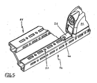
- Fig. 4 and Fig. 5 illustrates a first possibility of the mounting configuration of the housing 21 on a hole grid profile 55.
- Am. Perforated profile 55 profile sections 56 are formed with a plurality of through holes 57.
- the housing 21 is arranged on the profile section 56 such that the passage opening 46 of the fastening tab 26 is aligned with one of the passage openings of the profile section 56.
- the housing 21 is connected via the mounting strap 26 with a bolt, screw, or detent pin connection not shown here with the hole grid profile 55.
- the fastening tab 26 through the in Fig. 3 shown raster device adapted to different longitudinal distances of through holes 57 in the profile section 56.
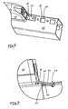
- the synopsis Fig. 6 and Fig. 7 shows a further embodiment of a mounting configuration between the housing 21 and a perforated grid profile 58.
- the perforated grid profile 58 is provided with a plurality of rectangular through openings 59 into which the fastening tab 26 can be inserted.
- the fastening tab 26 is angled in a bending region 60 from its planar extent in an engaging in the through hole 59 mounting position.
- the fastening projection 44 of the fastening tab 26 engages with a
- the fastening tab 26 engages so by means of the locking lug 61 in the through hole 59 and allows a positive connection of the housing 21 with the hole grid profile 58th
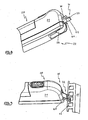
- FIG. 8 shows a third embodiment of a mounting configuration of the housing 21 of the lamp 20 with a hole grid profile 65.
- a housing end 66 of the housing 21 opposite, not shown housing end adds to the hole grid profile 65 parallel matching hole grid profile.
- the housing 21 is thus received in the space between the hole grid profiles at right angles to the hole grid profiles.
- Fig. 8 shows the pivot base 23 inserted in the housing 21 with the fastening tab 41 on which the fastening projection 42 is formed.
- the fastening tab 41 is in the in Fig. 8 shown representation in an outer end position 71st
- Fig. 9 shows an end position 71 of the housing 21 and the fastening tab 41 is inserted by inserting the fastening projection 42 in the through hole 73 and by a movement of the housing 21 in the direction of Arrow 74, as in Fig. 10 shown achieved.
- the pivoting base 23 engages in the end position 71 by a latching device, not shown here, in the housing 21.
Landscapes
- Engineering & Computer Science (AREA)
- General Engineering & Computer Science (AREA)
- Clamps And Clips (AREA)
- Non-Portable Lighting Devices Or Systems Thereof (AREA)
- Pivots And Pivotal Connections (AREA)
- Arrangements Of Lighting Devices For Vehicle Interiors, Mounting And Supporting Thereof, Circuits Therefore (AREA)
- Illuminated Signs And Luminous Advertising (AREA)
- Arrangement Of Elements, Cooling, Sealing, Or The Like Of Lighting Devices (AREA)
Description
- Die Erfindung betrifft eine Befestigungsvorrichtung für ein Gehäuse, insbesondere Leuchtengehäuse, mit zumindest zwei Anschlusseinrichtungsaufnahmen, wobei die Anschlusseinrichtungsaufnahmen jeweils zur Aufnahme einer räumlich positionierenden Befestigungseinrichtung an einer schwenkbar am Gehäuse angeordneten Schwenkbasis angeordnet sind.
- Das technische Gebiet der Erfindung betrifft insbesondere die Befestigung von Anbauteilen an technischen Einrichtungen, wie beispielsweise Leuchten, die zur Beleuchtung technischen Einrichtungen zum Einsatz kommen. Insbesondere werden Befestigungsvorrichtungen dieser Art zur Befestigung von Leuchten in Schränken oder an Regalen, die aus horizontalen und vertikalen Profilen gebildet sind bzw. diese beinhalten, eingesetzt. Werden Profile als Befestigungsbasis für diese Gehäuse verwendet, so sind die Profile häufig als Lochrasterprofil mit einem definierten Lochabstand ausgebildet. Die Montage dieser Gehäuse soll in der Regel möglichst schnell und einfach erfolgen, und die Befestigungstechnik muss leicht an die jeweiligen technischen Gegebenheiten anpassbar sein.
- Aus dem Stand der Technik sind in Verbindung mit Befestigungsvorrichtungen dieser Art eine Reihe von Befestigungstechniken bekannt, wie z.B. Schraubverbindungen, magnetische Halteverbindungen, Steck- oder Rastverbindungen. Die bekannten Befestigungsvorrichtungen ermöglichen eine Gehäusemontage in lediglich einer Befestigungsebene, da die Befestigungseinrichtung in ihrer Relativposition zum Gehäuse festgelegt ist.
- Aus der
EP 0 754 906 A2 ist eine Deckeneinbauleuchte bekannt, bei der hebelförmige Befestigungseinrichtungen schwenkbar an einem Gehäuse der Deckenleuchte gelagert sind. Durch Betätigung eines Seilzugs können die Hebel in eine die äußeren Gehäuseabmessungen überragende Befestigungskonfiguration überführt werden. - Die
US 1,045,859 beschreibt eine Deckeneinbauleuchte, bei der ein Gehäuse der Deckeneinbauleuchte mittels einer Befestigungsvorrichtung an Bauteilen einer Decke fixierbar ist. Die Befestigungsvorrichtung umfasst zwei Anschlusseinrichtungsaufnahmen, die jeweils an einer schwenkbar am Gehäuse angeordneten Schwenkbasis angeordnet sind. An den Anschlusseinrichtungsaufnahmen ist jeweils eine räumlich positionierbare Befestigungseinrichtung ausgebildet. Durch Anziehen einer jeweils die Schwenkbasis ausbildenden Schraube werden die Befestigungseinrichtungen in ihrer Lage fixiert. - Aufgabe der Erfindung ist es, eine Befestigungsvorrichtung vorzuschlagen, die eine Befestigung des Gehäuses in unterschiedlichen Befestigungsebenen oder Befestigungskonfigurationen zulässt.
- Diese Aufgabe wird durch eine Befestigungsvorrichtung mit den Merkmalen des Anspruchs 1 gelöst.
- Die erfindungsgemäße Befestigungsvorrichtung für ein Gehäuse weist zumindest zwei Anschlusseinrichtungsaufnahmen auf, wobei die Anschlusseinrichtungsaufnahmen jeweils zur Aufnahme einer räumlich positionierenden Befestigungseinrichtung an einer schwenkbar am Gehäuse angeordneten Schwenkbasis angeordnet sind, und wobei die Befestigungseinrichtung längsverschiebbar zu den Anschlusseinrichtungsaufnahmen ist. Die räumlich positionierende Befestigungseinrichtung dient der Veränderung der Gehäusepositionierung in einer Befestigungsebene und der Verbindung des Gehäuses mit einer Befestigungsbasis. Durch die schwenkbar am Gehäuse angeordnete Schwenkbasis ist die Montage des Gehäuse in räumlich unterschiedlichen Befestigungskonfigurationen in Verbindung mit den jeweils geeigneten Befestigungseinrichtungen möglich.
- In einer vorteilhaften Ausführungsform der Befestigungsvorrichtung können die Befestigungseinrichtungen als Befestigungslaschen mit einer Befestigungsbohrung zur Herstellung einer Bolzenverbindung mit einer Befestigungsbasis ausgebildet sein. Mit derartigen Befestigungslaschen kann leicht eine Schraub-, Raststift- oder Nietverbindung mit einer Befestigungsbasis hergestellt werden.
- In einer weiteren vorteilhaften Ausführungsform können die Befestigungseinrichtungen als Befestigungslaschen mit einem Befestigungsvorsprung zum Eingriff in eine Befestigungsbasis ausgebildet sein. Dies ermöglicht das Einsetzen oder Einrasten der Befestigungslaschen in Durchgangsöffnungen einer Befestigungsbasis und somit eine formschlüssige Befestigung des Gehäuses auf der Befestigungsbasis.
- Zur Anpassung eines Gehäuses mit einer Befestigungsvorrichtung auf eine Befestigungsbasis, wie z.B. einem Lochrasterprofil, können die Anschlusseinrichtungsaufnahmen der Befestigungsvorrichtung zur Aufnahme einer Befestigungslasche eine Führungsaufnahme zur längsverschiebbaren Anordnung der Bcfestigungslasche aufweisen. Dies ermöglicht die Ausrichtung axial voneinander beabstandeter Befestigungslaschen auf einen vorgegebenen Lochabstand zur Verschraubung mit oder zum Eingriff in ein Lochrasterprofil.
- Besonders vorteilhaft ist es, wenn die Führungsaufnahme mit einer Rastereinrichtung zur Relativpositionierung der Befestigungslasche versehen ist. Durch die Rastereinrichtung kann eine feste Einstellung zweier, axial voneinander beabstandeter Befestigungslaschen auf einem vorgegebenen Lochrasterabstand einer Befestigungsbasis erfolgen. Ebenso kann eine feste Einstellung eines Befestigungsvorsprungs auf einen vorgegebenen Lochrasterabstand erfolgen.
- Als besonders vorteilhaft erweist es sich, wenn das Gehäuse jeweils an seinen axialen Enden mit einer Schwenkbasis zum Verschwenken der Befestigungseinrichtungen in eine, die äußeren Gehäuseabmessungen axial überragende Befestigungskonfiguration versehen ist. Das Gehäuse kann so, mit jeweils einer an der Schwenkbasis ausgebildeten Befestigungslasche, zwischen zwei parallel zueinander angeordneten Lochprofilen, wie beispielsweise in einem Schaltschrank mit 19 Zoll Gehäuseaufnahmen, angeordnet werden. Die Befestigungslaschen können derart verschwenkt werden, dass sie jeweils in einer Durchgangsöffnung im Lochrasterprofil eingreifen und durch Verschwenken in eine axiale Lage längs zum Gehäuse formschlüssig in die Durchgangsöffnungen der Lochrasterprofile einsetzbar sind. Das Gehäuse kann so zwischen zwei Lochrasterprofilen ohne zusätzliches Werkzeug und Zubehörteile montiert werden.
- Ist die Schwenkbasis mit einer Rastereinrichtung zur Relativpositionierung der Befestigungseinrichtung versehen, kann durch Einrasten der Schwenkbasis am Gehäuse eine Fixierung der Befestigungskonfiguration, z.B. des Gehäuses zwischen zwei Lochrasterprofilen, erreicht werden. Weiter erweist es sich als vorteilhaft, wenn die Schwenkbasis in drei verschiedene Positionen am Gehäuse einrastet. So kann die Schwenkbasis in einer Verwahrposition, in einer Montageposition und in einer Endposition fixiert werden. Dies erleichtert das Einsetzen des Gehäuses zwischen zwei Lochrasterprofilen wesentlich.
- Im Folgenden wird die Erfindung unter Bezugnahme auf die beigefügte Zeichnung näher erläutert.
- Es zeigen:
- Fig. 1:
- ein Gehäuse mit einer Befestigungsvorrichtung;
- Fig. 2-3:
- eine Schwenkbasis zur schwenkbaren Anordnung an einem Gehäuse mit zwei Befestigungseinrichtungen;
- Fig. 4-5:
- ein Gehäuse in einer ersten Befestigungskonfiguration;
- Fig. 6-7:
- ein Gehäuse in einer zweiten Befestigungskonfiguration;
- Fig. 8-10:
- ein Gehäuse in einer dritten Befestigungskonfiguration.
- In
Fig. 1 ist eine Leuchte 20 mit einer an einem Gehäuse 21 angeordneten Befestigungsvorrichtung 22 dargestellt. Die Befestigungsvorrichtung 22 umfasst eine erste Schwenkbasis 23 und eine hier nur schematisch dargestellte zweite Schwenkbasis 24. An beiden Schwenkbasen 23 und 24 ist - wie inFig. 1 lediglich am Beispiel der Schwenkbasis 23 dargestellt - eine als Befestigungslasche 26 ausgebildete Befestigungseinrichtung angeordnet, die in einer Anschlusseinrichtungsaufnahme 27 aufgenommen ist. - Die Befestigungslaschen sind durch ihre Anordnung an den Schwenkbasen 23 und 24 schwenkbar mit dem Gehäuse 21 verbunden. In der dargestellten Verwahrposition ist die Befestigungslasche 26 der Befestigungsvorrichtung 22 nicht unmittelbar für eine Montage auf einer hier nicht dargestellten Befestigungsbasis nutzbar.
-
Fig. 2 undFig. 3 zeigen die Schwenkbasis 23, an der eine Schwenkachse 31 ausgebildet ist, die in hier nicht dargestellte Ausnehmungen des Gehäuses 21 einsetzbar ist. Auf einem äußeren, weitestgehend ringförmigen Umfangskörper 32 der Schwenkbasis 23 sind an dessen Seitenfläche Rastausnehmungen 33, 34, 35 und 36 ausgebildet. Die Rastausnehmungen 33, 34, 35 und 36 greifen in eine hier nicht dargestellte Rastnase eines Gehäuses ein und ermöglichen somit eine Fixierung der Schwenkbasis 23 relativ zum Gehäuse 21 in einer Verwahrposition, Montageposition und Endposition ohne das Werkzeuge verwendet werden müssten. - Neben der ersten Befestigungslasche 26 ist an den Schwenkbasen 23, 24 jeweils eine zweite Befestigungslasche 41 ausgebildet, die einen Befestigungsvorsprung 42 zum Einsetzen in eine hier nicht dargestellte Durchgangsöffnung eines Lochrasterprofils ausgebildet. Die Befestigungslasche 26 weist zudem Befestigungsvorsprünge 44 und 45 und eine Durchgangsöffnung 46 auf. Die Befestigungsvorsprünge 44 und 45 dienen bei einer Verschraubung mit einer hier nicht dargestellten Befestigungsbasis als Auflagereinrichtung, um die Befestigungslasche 26 gegenüber einer Befestigungsbasis flächenparallel anzuordnen. Die Befestigungslasche 26 ist in der Führungsaufnahme 25 längsverschiebbar eingesetzt und durch Führungsstege 48, 49 im Zusammenspiel mit einem Anschlag 50 gegen Herausfallen gesichert. Seitenflächen 51, 52 der Führungsaufnahme 25 sind mit einer Mehrzahl Rastausnehmungen 53 versehen, in die hier nicht sichtbare, an der Befestigungslasche 26 ausgebildete Rastnasen eingreifen. Die Befestigungslasche 26 ist somit in einer definierten Position relativ zu einem Gehäuse fixierbar.
-
Fig. 4 zeigt einen Bestandteil einer Befestigungsvorrichtung 22 mit der inFig. 2 undFig. 3 dargestellten Schwenkbasis 23, die in dem Gehäuse 21 aufgenommen ist sowie die Befestigungslasche 26 in der Führungsaufnahme 25 in einer äußeren Position relativ zum Gehäuse 21. - Die Zusammenschau von
Fig. 4 undFig. 5 verdeutlicht eine erste Möglichkeit der Befestigungskonfiguration des Gehäuses 21 auf einem Lochrasterprofil 55. Am. Lochrasterprofil 55 sind Profilabschnitte 56 mit einer Vielzahl von Durchgangsöffnungen 57 ausgebildet. Das Gehäuse 21 ist derart am Profilabschnitt 56 angeordnet, dass die Durchgangsöffnung 46 der Befestigungslasche 26 mit einer der Durchgangsöffnungen des Profilabschnittes 56 fluchtet. Das Gehäuse 21 ist so über die Befestigungslasche 26 mit einer hier nicht näher dargestellten Bolzen-, Schrauben-, oder Raststiftverbindung mit dem Lochrasterprofil 55 verbindbar. Weiter ist die Befestigungslasche 26 durch die inFig. 3 gezeigte Rastereinrichtung auf unterschiedliche Längsabstände von Durchgangsöffnungen 57 im Profilabschnitt 56 anpassbar. - Die Zusammenschau aus
Fig. 6 und Fig. 7 zeigt ein weiteres Ausführungsbeispiel einer Befestigungskonfiguration zwischen dem Gehäuse 21 und einem Lochrasterprofil 58. Das Lochrasterprofil 58 ist mit einer Vielzahl von rechteckigen Durchgangsöffnungen 59 versehen, in die die Befestigungslasche 26 einsetzbar ist. Die Befestigungslasche 26 ist in einem Biegebereich 60 aus ihrer ebenen Erstreckung in eine, in die Durchgangsöffnung 59 eingreifende Montageposition abgewinkelt. Der Befestigungsvorsprung 44 der Befestigungslasche 26 greift mit einer daran ausgebildeten Rastnase 61 unter eine Kante 62 der Durchgangsöffnung 59. Die Befestigungslasche 26 rastet so vermittels der Rastnase 61 in der Durchgangsöffnung 59 ein und ermöglicht eine formschlüssige Verbindung des Gehäuses 21 mit dem Lochrasterprofil 58. - Eine Zusammenschau der
Fig. 8, Fig. 9 undFig. 10 zeigt ein drittes Ausführungsbeispiel einer Befestigungskonfiguration des Gehäuses 21 der Leuchte 20 mit einem Lochrasterprofil 65. An einem, einem Gehäuseende 66 des Gehäuses 21 gegenüberliegenden, hier nicht dargestellten Gehäuseende, fügt sich ein zum Lochrasterprofil 65 parallel verlaufendes übereinstimmendes Lochrasterprofil an. Das Gehäuse 21 ist somit im Zwischenraum zwischen den Lochrasterprofilen rechtwinklig zu den Lochrasterprofilen aufgenommen. -
Fig. 8 zeigt die im Gehäuse 21 eingesetzte Schwenkbasis 23 mit der Befestigungslasche 41, an der der Befestigungsvorsprung 42 ausgebildet ist. Die Befestigungslasche 41 ist in der in derFig. 8 gezeigten Darstellung in einer äußeren Endposition 71. -
Fig. 9 zeigt die Befestigungslasche 41 in einer Montageposition 72 vor Eingriff in eine rechteckige Durchgangsöffnung 73 des Lochrasterprofils 65. Eine Endposition 71 des Gehäuses 21 bzw. der Befestigungslasche 41 wird durch Einsetzen des Befestigungsvorsprunges 42 in die Durchgangsöffnung 73 und durch eine Bewegung des Gehäuses 21 in Richtung des Pfeils 74, wie inFig. 10 dargestellt, erreicht. Die Schwenkbasis 23 rastet so durch eine hier nicht dargestellte Rasteinrichtung im Gehäuse 21 in der Endposition 71 ein. Weiter greift der Befestigungsvorsprung 42 beim Einsetzen in die Durchgangsöffnung 73 hinter eine Kante 75 der Durchgangsöffnung 73 und verspannt so eine Unterseite 76 der Befestigungslasche 41 mit einer Oberseite 77 des Befestigungsvorsprunges 42, was bei einem gleichzeitigen Einrasten von jeweiligen, an den Gehäuseenden 66 des Gehäuses 21 aufgenommenen Schwenkbasen 23, 24 zu einer formschlüssigen Befestigung des Gehäuses 21 zwischen den Lochrasterprofilen 65 führt.
Claims (7)
- Befestigungsvorrichtung (22) für ein Gehäuse (21), insbesondere Leuchtengehäuse, wobei die Befestigungsvorrichtung zumindest zwei Anschlusseinrichtungsaufnahmen (27) aufweist, wobei die Anschlusseinrichtungsaufnahmen jeweils an einer schwenkbar am Gehäuse angeordneten Schwenkbasis (23, 24) angeordnet sind, und wobei die Anschlusseinrichtungsaufnahmen jeweils zur Aufnahme einer räumlich positionierenden Befestigungseinrichtung dienen
dadurch gekennzeichnet,
dass die Befestigungseinrichtung längsverschiebbar zu den Anschlusseinrichtungsaufnahmen ist. - Befestigungsvorrichtung nach Anspruch 1,
dadurch gekennzeichnet,
dass die Befestigungseinrichtungen als Befestigungslaschen (26) mit einer Befestigungsbohrung (46) zur Herstellung einer Bolzenverbindung mit einer Befestigungsbasis ausgebildet sind. - Befestigungsvorrichtung nach Anspruch 1,
dadurch gekennzeichnet,
dass die Befestigungseinrichtungen als Befestigungslaschen (26, 41) mit einem Befestigungsvorsprung (42, 44, 45) zum Eingriff in eine Befestigungsbasis ausgebildet sind. - Befestigungsvorrichtung nach Anspruch 2 oder 3,
dadurch gekennzeichnet,
dass die Anschlusseinrichtungsaufnahmen zur Aufnahme einer Befestigungslasche eine Führungsaufnahme (25) zur längsverschiebbaren Anordnung der Befestigungslasche (26) aufweist. - Befestigungsvorrichtung nach Anspruch 4,
dadurch gekennzeichnet,
dass die Führungsaufnahme mit einer Rastereinrichtung zur Relativpositionierung der Befestigungslasche versehen ist. - Befestigungsvorrichtung nach einem der vorangehenden Ansprüche,
dadurch gekennzeichnet,
dass die Befestigungseinrichtungen jeweils an einem axialen Ende (66) des Gehäuses zum Verschwenken der Befestigungseinrichtungen in eine die äußeren Gehäuseabmessungen axial überragende Befestigungskonfiguration angeordnet sind. - Befestigungsvorrichtung nach einem der vorangehenden Ansprüche,
dadurch gekennzeichnet,
dass die Schwenkbasis mit einer Rastereinrichtung zur Relativpositionierung der Befestigungseinrichtungen versehen ist.
Applications Claiming Priority (1)
| Application Number | Priority Date | Filing Date | Title |
|---|---|---|---|
| DE102006029807A DE102006029807B4 (de) | 2006-06-27 | 2006-06-27 | Befestigungsvorrichtung mit Schwenkbasis |
Publications (3)
| Publication Number | Publication Date |
|---|---|
| EP1873403A2 EP1873403A2 (de) | 2008-01-02 |
| EP1873403A3 EP1873403A3 (de) | 2008-05-21 |
| EP1873403B1 true EP1873403B1 (de) | 2013-01-02 |
Family
ID=38650148
Family Applications (1)
| Application Number | Title | Priority Date | Filing Date |
|---|---|---|---|
| EP07012461A Active EP1873403B1 (de) | 2006-06-27 | 2007-06-26 | Befestigungsvorrichtung mit Schwenkbasis |
Country Status (4)
| Country | Link |
|---|---|
| US (1) | US20080002415A1 (de) |
| EP (1) | EP1873403B1 (de) |
| DE (1) | DE102006029807B4 (de) |
| ES (1) | ES2406554T3 (de) |
Cited By (1)
| Publication number | Priority date | Publication date | Assignee | Title |
|---|---|---|---|---|
| WO2017178010A1 (de) | 2016-04-15 | 2017-10-19 | Rittal Gmbh & Co. Kg | Elektronisches gerät für den einbau in einem schaltschrank, das ein erstes und ein zweites befestigungsmittel aufweist |
Families Citing this family (1)
| Publication number | Priority date | Publication date | Assignee | Title |
|---|---|---|---|---|
| DE102014013658B4 (de) * | 2014-09-15 | 2020-06-18 | Hoffmeister Leuchten Gmbh | Montagesystem, Befestigungseinrichtung und Verfahren zur Befestigung einer Leuchte und Leuchte mit einer Befestigungseinrichtung |
Family Cites Families (23)
| Publication number | Priority date | Publication date | Assignee | Title |
|---|---|---|---|---|
| US632858A (en) * | 1898-10-27 | 1899-09-12 | Manhattan Brass Company | Bicycle-lamp bracket. |
| US1045859A (en) | 1908-10-21 | 1912-12-03 | H W Johns | Ignition device for gas-engines. |
| DE1278372B (de) * | 1963-04-16 | 1968-09-26 | Trilux Lenze Gmbh & Co Kg | Vorrichtung zum Anbringen von Einbauleuchten zwischen zwei Deckentraegern |
| US3832503A (en) * | 1973-08-10 | 1974-08-27 | Keene Corp | Two circuit track lighting system |
| US4372068A (en) * | 1980-08-04 | 1983-02-08 | Frederick A. Major | Rechargeable transparent slide viewer apparatus |
| FR2500088A1 (fr) * | 1981-02-18 | 1982-08-20 | Art Tech Decoration Sarl | Piece de jonction pour elements profiles |
| DE8717002U1 (de) * | 1987-12-24 | 1988-02-18 | Kotzolt-Leuchten L. & G. Kotzolt GmbH & Co KG, 4920 Lemgo | Befestigungsvorrichtung für Einbaugehäuse |
| DE8907227U1 (de) * | 1989-06-13 | 1989-08-03 | Fuchs, Andreas, 6822 Altlußheim | Halter für einen Lautsprecher, Beleuchtungskörper o. ä. |
| DE9209335U1 (de) * | 1992-07-11 | 1992-09-03 | Licentia Patent-Verwaltungs-Gmbh, 6000 Frankfurt | Haltevorrichtung einer Wandleuchte |
| DE19526196A1 (de) | 1995-07-18 | 1997-01-23 | Hartmut S Engel | Befestigungsvorrichtung |
| ATE429798T1 (de) * | 1999-09-17 | 2009-05-15 | Brightline L P | Verstellbare fluoreszierende beleuchtungsvorrichtung |
| US6260990B1 (en) * | 1999-11-09 | 2001-07-17 | Gerald N. Saunders | Truck lights |
| DE10051428A1 (de) * | 2000-10-17 | 2002-04-18 | Walter Waibel | Aufbewahrungsmöbel, insbesondere für Büroeinrichtungen, Beschlag hierfür sowie hiermit errichtetes Möbelsystem |
| DE20205378U1 (de) * | 2002-04-06 | 2002-08-08 | Richter, Jörg, 57567 Daaden | Schaltschrankleuchte |
| US20050265033A1 (en) * | 2004-05-25 | 2005-12-01 | Yang A M | Light device for attaching to various tools |
| US20060050519A1 (en) * | 2004-09-03 | 2006-03-09 | Jack Lin | Multi angles extending desk lamp |
| US7249873B2 (en) * | 2004-09-07 | 2007-07-31 | Lear Corporation | Adjustable light beam device for aimable vehicle lamp assembly and method |
| US20060083010A1 (en) * | 2004-10-15 | 2006-04-20 | Great Neck Saw Manufacturers, Inc. | Detachable lamp |
| DE202006004367U1 (de) * | 2006-03-16 | 2006-05-11 | Richter, Jörg | Schaltschrank mit einer Sicherheitsabdeckung von außenliegenden Schaltelementen, Sicherheitsabdeckung für einen derartigen Schaltschrank sowie Profilstab für eine derartige Sicherheitsabdeckung |
| US7484866B1 (en) * | 2006-05-09 | 2009-02-03 | Genlyte Thomas Group Llc | Adjustable lighting fixture for sloped ceiling |
| US7322735B1 (en) * | 2006-07-21 | 2008-01-29 | Minka Lighting, Inc. | Telescoping power medium |
| US7988343B2 (en) * | 2007-04-26 | 2011-08-02 | Palmisano Jr Lester J | Easy-glide offshore ready light tower system |
| US7731386B2 (en) * | 2008-05-24 | 2010-06-08 | Levine Jonathan E | Lighting device |
-
2006
- 2006-06-27 DE DE102006029807A patent/DE102006029807B4/de not_active Expired - Fee Related
-
2007
- 2007-06-26 ES ES07012461T patent/ES2406554T3/es active Active
- 2007-06-26 US US11/768,858 patent/US20080002415A1/en not_active Abandoned
- 2007-06-26 EP EP07012461A patent/EP1873403B1/de active Active
Cited By (4)
| Publication number | Priority date | Publication date | Assignee | Title |
|---|---|---|---|---|
| WO2017178010A1 (de) | 2016-04-15 | 2017-10-19 | Rittal Gmbh & Co. Kg | Elektronisches gerät für den einbau in einem schaltschrank, das ein erstes und ein zweites befestigungsmittel aufweist |
| DE102016107044A1 (de) | 2016-04-15 | 2017-10-19 | Rittal Gmbh & Co. Kg | Elektronisches Gerät für den Einbau in einem Schaltschrank, das ein erstes und ein zweites Befestigungsmittel aufweist |
| DE102016107044B4 (de) * | 2016-04-15 | 2017-11-16 | Rittal Gmbh & Co. Kg | Elektronisches Gerät für den Einbau in einem Schaltschrank, das ein erstes und ein zweites Befestigungsmittel aufweist |
| US10415807B2 (en) | 2016-04-15 | 2019-09-17 | Rittal Gmbh & Co. Kg | Electronic device for installing in a switch cabinet, which electronic device has a first and a second fastener |
Also Published As
| Publication number | Publication date |
|---|---|
| ES2406554T3 (es) | 2013-06-07 |
| EP1873403A2 (de) | 2008-01-02 |
| US20080002415A1 (en) | 2008-01-03 |
| DE102006029807B4 (de) | 2013-01-17 |
| DE102006029807A1 (de) | 2008-01-03 |
| EP1873403A3 (de) | 2008-05-21 |
Similar Documents
| Publication | Publication Date | Title |
|---|---|---|
| DE102009011904B4 (de) | Verbindungsvorrichtung | |
| EP2248503A1 (de) | Medizinische Versorgungseinheit mit verriegelbaren Adaptern | |
| EP2410618B1 (de) | Sekundärverriegelungsmittel und Steckverbindergehäuse mit einem Sekundärverriegelungsmittel | |
| DE202015100360U1 (de) | Kabelhalter und Kabelhaltersystem | |
| EP1999830B1 (de) | Geräteeinbausatz zur anordnung eines gerätes in einer elektrischen schaltanlage | |
| EP1873403B1 (de) | Befestigungsvorrichtung mit Schwenkbasis | |
| WO2019025140A1 (de) | Elektrisches reiheneinbaugerät und reiheneinbaugeräte-anordnung | |
| EP2019259B1 (de) | Verbindungssytem für Tragschienen von Leuchteneinsätzen eines Lichtbandes | |
| DE202010015763U1 (de) | Vorrichtung zur Positionierung wenigstens eines Rundsteckers | |
| DE102010054156B4 (de) | Terminalsystem zum Anbringen eines Endgerätes an einem Ständerwerk und zum elektrischen Koppeln des Endgerätes an ein Netzwerk oder eine Verarbeitungseinheit | |
| DE202018102643U1 (de) | Adapter für schwere Leuchten | |
| EP3396655A1 (de) | Led-panel | |
| EP3891849A1 (de) | Adaptergehäuse für einen kontakteinsatz zur fixierung auf einer hutschiene | |
| DE202018106703U1 (de) | Wand- oder Deckenleuchte | |
| DE102006029826B4 (de) | Leuchtenbefestigungsvorrichtung | |
| EP3604897B1 (de) | Haltesystem einer aufbauleuchte, aufbauleuchte sowie leuchte hierfür | |
| DE102024100353B4 (de) | Leuchte mit verriegelbarem Befestigungsabgriff und Verfahren zur Montage einer Leuchte | |
| WO2015193190A1 (de) | Beleuchtungsanordnung | |
| EP3772788A1 (de) | Befestigungselement und befestigungssystem | |
| WO2009121588A1 (de) | Zugentlastungs-vorrichtung | |
| EP3931924B1 (de) | Schaltschrankanordnung mit einem schaltschrank und mindestens einer steckdosenleiste | |
| DE102019101050A1 (de) | Zugentlastung für ein Haushaltsgerät zur Klemmung eines Kabels des Haushaltsgeräts | |
| DE102016115488B3 (de) | Anbaugehäuse | |
| DE3721679A1 (de) | Steckanschluss | |
| DE102010022456B3 (de) | Trägervorrichtung |
Legal Events
| Date | Code | Title | Description |
|---|---|---|---|
| PUAI | Public reference made under article 153(3) epc to a published international application that has entered the european phase |
Free format text: ORIGINAL CODE: 0009012 |
|
| AK | Designated contracting states |
Kind code of ref document: A2 Designated state(s): AT BE BG CH CY CZ DE DK EE ES FI FR GB GR HU IE IS IT LI LT LU LV MC MT NL PL PT RO SE SI SK TR |
|
| AX | Request for extension of the european patent |
Extension state: AL BA HR MK YU |
|
| PUAL | Search report despatched |
Free format text: ORIGINAL CODE: 0009013 |
|
| AK | Designated contracting states |
Kind code of ref document: A3 Designated state(s): AT BE BG CH CY CZ DE DK EE ES FI FR GB GR HU IE IS IT LI LT LU LV MC MT NL PL PT RO SE SI SK TR |
|
| AX | Request for extension of the european patent |
Extension state: AL BA HR MK RS |
|
| RIC1 | Information provided on ipc code assigned before grant |
Ipc: F21V 21/02 20060101AFI20080415BHEP |
|
| 17P | Request for examination filed |
Effective date: 20081113 |
|
| AKX | Designation fees paid |
Designated state(s): AT BE BG CH CY CZ DE DK EE ES FI FR GB GR HU IE IS IT LI LT LU LV MC MT NL PL PT RO SE SI SK TR |
|
| 17Q | First examination report despatched |
Effective date: 20090212 |
|
| GRAP | Despatch of communication of intention to grant a patent |
Free format text: ORIGINAL CODE: EPIDOSNIGR1 |
|
| GRAS | Grant fee paid |
Free format text: ORIGINAL CODE: EPIDOSNIGR3 |
|
| GRAA | (expected) grant |
Free format text: ORIGINAL CODE: 0009210 |
|
| AK | Designated contracting states |
Kind code of ref document: B1 Designated state(s): AT BE BG CH CY CZ DE DK EE ES FI FR GB GR HU IE IS IT LI LT LU LV MC MT NL PL PT RO SE SI SK TR |
|
| REG | Reference to a national code |
Ref country code: GB Ref legal event code: FG4D Free format text: NOT ENGLISH |
|
| REG | Reference to a national code |
Ref country code: CH Ref legal event code: EP Ref country code: AT Ref legal event code: REF Ref document number: 591822 Country of ref document: AT Kind code of ref document: T Effective date: 20130115 |
|
| REG | Reference to a national code |
Ref country code: IE Ref legal event code: FG4D Free format text: LANGUAGE OF EP DOCUMENT: GERMAN |
|
| REG | Reference to a national code |
Ref country code: DE Ref legal event code: R096 Ref document number: 502007011129 Country of ref document: DE Effective date: 20130228 |
|
| REG | Reference to a national code |
Ref country code: CH Ref legal event code: NV Representative=s name: FREI PATENTANWALTSBUERO AG, CH |
|
| REG | Reference to a national code |
Ref country code: NL Ref legal event code: VDEP Effective date: 20130102 |
|
| PG25 | Lapsed in a contracting state [announced via postgrant information from national office to epo] |
Ref country code: SI Free format text: LAPSE BECAUSE OF FAILURE TO SUBMIT A TRANSLATION OF THE DESCRIPTION OR TO PAY THE FEE WITHIN THE PRESCRIBED TIME-LIMIT Effective date: 20130102 |
|
| REG | Reference to a national code |
Ref country code: ES Ref legal event code: FG2A Ref document number: 2406554 Country of ref document: ES Kind code of ref document: T3 Effective date: 20130607 |
|
| REG | Reference to a national code |
Ref country code: LT Ref legal event code: MG4D |
|
| PG25 | Lapsed in a contracting state [announced via postgrant information from national office to epo] |
Ref country code: CZ Free format text: LAPSE BECAUSE OF FAILURE TO SUBMIT A TRANSLATION OF THE DESCRIPTION OR TO PAY THE FEE WITHIN THE PRESCRIBED TIME-LIMIT Effective date: 20130102 Ref country code: SE Free format text: LAPSE BECAUSE OF FAILURE TO SUBMIT A TRANSLATION OF THE DESCRIPTION OR TO PAY THE FEE WITHIN THE PRESCRIBED TIME-LIMIT Effective date: 20130102 Ref country code: IS Free format text: LAPSE BECAUSE OF FAILURE TO SUBMIT A TRANSLATION OF THE DESCRIPTION OR TO PAY THE FEE WITHIN THE PRESCRIBED TIME-LIMIT Effective date: 20130502 Ref country code: BG Free format text: LAPSE BECAUSE OF FAILURE TO SUBMIT A TRANSLATION OF THE DESCRIPTION OR TO PAY THE FEE WITHIN THE PRESCRIBED TIME-LIMIT Effective date: 20130402 Ref country code: LT Free format text: LAPSE BECAUSE OF FAILURE TO SUBMIT A TRANSLATION OF THE DESCRIPTION OR TO PAY THE FEE WITHIN THE PRESCRIBED TIME-LIMIT Effective date: 20130102 |
|
| PG25 | Lapsed in a contracting state [announced via postgrant information from national office to epo] |
Ref country code: LV Free format text: LAPSE BECAUSE OF FAILURE TO SUBMIT A TRANSLATION OF THE DESCRIPTION OR TO PAY THE FEE WITHIN THE PRESCRIBED TIME-LIMIT Effective date: 20130102 Ref country code: GR Free format text: LAPSE BECAUSE OF FAILURE TO SUBMIT A TRANSLATION OF THE DESCRIPTION OR TO PAY THE FEE WITHIN THE PRESCRIBED TIME-LIMIT Effective date: 20130403 Ref country code: FI Free format text: LAPSE BECAUSE OF FAILURE TO SUBMIT A TRANSLATION OF THE DESCRIPTION OR TO PAY THE FEE WITHIN THE PRESCRIBED TIME-LIMIT Effective date: 20130102 Ref country code: PT Free format text: LAPSE BECAUSE OF FAILURE TO SUBMIT A TRANSLATION OF THE DESCRIPTION OR TO PAY THE FEE WITHIN THE PRESCRIBED TIME-LIMIT Effective date: 20130502 Ref country code: NL Free format text: LAPSE BECAUSE OF FAILURE TO SUBMIT A TRANSLATION OF THE DESCRIPTION OR TO PAY THE FEE WITHIN THE PRESCRIBED TIME-LIMIT Effective date: 20130102 Ref country code: PL Free format text: LAPSE BECAUSE OF FAILURE TO SUBMIT A TRANSLATION OF THE DESCRIPTION OR TO PAY THE FEE WITHIN THE PRESCRIBED TIME-LIMIT Effective date: 20130102 |
|
| PG25 | Lapsed in a contracting state [announced via postgrant information from national office to epo] |
Ref country code: SK Free format text: LAPSE BECAUSE OF FAILURE TO SUBMIT A TRANSLATION OF THE DESCRIPTION OR TO PAY THE FEE WITHIN THE PRESCRIBED TIME-LIMIT Effective date: 20130102 Ref country code: RO Free format text: LAPSE BECAUSE OF FAILURE TO SUBMIT A TRANSLATION OF THE DESCRIPTION OR TO PAY THE FEE WITHIN THE PRESCRIBED TIME-LIMIT Effective date: 20130102 Ref country code: DK Free format text: LAPSE BECAUSE OF FAILURE TO SUBMIT A TRANSLATION OF THE DESCRIPTION OR TO PAY THE FEE WITHIN THE PRESCRIBED TIME-LIMIT Effective date: 20130102 Ref country code: EE Free format text: LAPSE BECAUSE OF FAILURE TO SUBMIT A TRANSLATION OF THE DESCRIPTION OR TO PAY THE FEE WITHIN THE PRESCRIBED TIME-LIMIT Effective date: 20130102 |
|
| PLBE | No opposition filed within time limit |
Free format text: ORIGINAL CODE: 0009261 |
|
| PG25 | Lapsed in a contracting state [announced via postgrant information from national office to epo] |
Ref country code: CY Free format text: LAPSE BECAUSE OF FAILURE TO SUBMIT A TRANSLATION OF THE DESCRIPTION OR TO PAY THE FEE WITHIN THE PRESCRIBED TIME-LIMIT Effective date: 20130102 |
|
| 26N | No opposition filed |
Effective date: 20131003 |
|
| BERE | Be: lapsed |
Owner name: POLYCADFORM E.K. Effective date: 20130630 |
|
| PG25 | Lapsed in a contracting state [announced via postgrant information from national office to epo] |
Ref country code: IT Free format text: LAPSE BECAUSE OF FAILURE TO SUBMIT A TRANSLATION OF THE DESCRIPTION OR TO PAY THE FEE WITHIN THE PRESCRIBED TIME-LIMIT Effective date: 20130102 |
|
| REG | Reference to a national code |
Ref country code: DE Ref legal event code: R097 Ref document number: 502007011129 Country of ref document: DE Effective date: 20131003 |
|
| PG25 | Lapsed in a contracting state [announced via postgrant information from national office to epo] |
Ref country code: MC Free format text: LAPSE BECAUSE OF FAILURE TO SUBMIT A TRANSLATION OF THE DESCRIPTION OR TO PAY THE FEE WITHIN THE PRESCRIBED TIME-LIMIT Effective date: 20130102 |
|
| REG | Reference to a national code |
Ref country code: IE Ref legal event code: MM4A |
|
| PG25 | Lapsed in a contracting state [announced via postgrant information from national office to epo] |
Ref country code: BE Free format text: LAPSE BECAUSE OF NON-PAYMENT OF DUE FEES Effective date: 20130630 |
|
| PG25 | Lapsed in a contracting state [announced via postgrant information from national office to epo] |
Ref country code: IE Free format text: LAPSE BECAUSE OF NON-PAYMENT OF DUE FEES Effective date: 20130626 |
|
| PG25 | Lapsed in a contracting state [announced via postgrant information from national office to epo] |
Ref country code: MT Free format text: LAPSE BECAUSE OF FAILURE TO SUBMIT A TRANSLATION OF THE DESCRIPTION OR TO PAY THE FEE WITHIN THE PRESCRIBED TIME-LIMIT Effective date: 20130102 |
|
| PG25 | Lapsed in a contracting state [announced via postgrant information from national office to epo] |
Ref country code: TR Free format text: LAPSE BECAUSE OF FAILURE TO SUBMIT A TRANSLATION OF THE DESCRIPTION OR TO PAY THE FEE WITHIN THE PRESCRIBED TIME-LIMIT Effective date: 20130102 |
|
| PG25 | Lapsed in a contracting state [announced via postgrant information from national office to epo] |
Ref country code: HU Free format text: LAPSE BECAUSE OF FAILURE TO SUBMIT A TRANSLATION OF THE DESCRIPTION OR TO PAY THE FEE WITHIN THE PRESCRIBED TIME-LIMIT; INVALID AB INITIO Effective date: 20070626 Ref country code: LU Free format text: LAPSE BECAUSE OF NON-PAYMENT OF DUE FEES Effective date: 20130626 |
|
| REG | Reference to a national code |
Ref country code: FR Ref legal event code: PLFP Year of fee payment: 10 |
|
| REG | Reference to a national code |
Ref country code: FR Ref legal event code: PLFP Year of fee payment: 11 |
|
| REG | Reference to a national code |
Ref country code: FR Ref legal event code: PLFP Year of fee payment: 12 |
|
| PGFP | Annual fee paid to national office [announced via postgrant information from national office to epo] |
Ref country code: SI Payment date: 20180417 Year of fee payment: 10 |
|
| REG | Reference to a national code |
Ref country code: CH Ref legal event code: PCAR Free format text: NEW ADDRESS: POSTFACH, 8032 ZUERICH (CH) |
|
| PGFP | Annual fee paid to national office [announced via postgrant information from national office to epo] |
Ref country code: FR Payment date: 20190626 Year of fee payment: 13 |
|
| PGFP | Annual fee paid to national office [announced via postgrant information from national office to epo] |
Ref country code: ES Payment date: 20190723 Year of fee payment: 13 |
|
| REG | Reference to a national code |
Ref country code: AT Ref legal event code: MM01 Ref document number: 591822 Country of ref document: AT Kind code of ref document: T Effective date: 20190626 |
|
| PG25 | Lapsed in a contracting state [announced via postgrant information from national office to epo] |
Ref country code: AT Free format text: LAPSE BECAUSE OF NON-PAYMENT OF DUE FEES Effective date: 20190626 |
|
| PG25 | Lapsed in a contracting state [announced via postgrant information from national office to epo] |
Ref country code: FR Free format text: LAPSE BECAUSE OF NON-PAYMENT OF DUE FEES Effective date: 20200630 |
|
| REG | Reference to a national code |
Ref country code: ES Ref legal event code: FD2A Effective date: 20211105 |
|
| PG25 | Lapsed in a contracting state [announced via postgrant information from national office to epo] |
Ref country code: ES Free format text: LAPSE BECAUSE OF NON-PAYMENT OF DUE FEES Effective date: 20200627 |
|
| REG | Reference to a national code |
Ref country code: DE Ref legal event code: R081 Ref document number: 502007011129 Country of ref document: DE Owner name: ICOTEK PROJECT GMBH & CO. KG, DE Free format text: FORMER OWNER: POLYCADFORM E.K., 35216 BIEDENKOPF, DE Ref country code: DE Ref legal event code: R082 Ref document number: 502007011129 Country of ref document: DE Representative=s name: DR. WEITZEL & PARTNER PATENT- UND RECHTSANWAEL, DE |
|
| REG | Reference to a national code |
Ref country code: GB Ref legal event code: 732E Free format text: REGISTERED BETWEEN 20220317 AND 20220323 |
|
| P01 | Opt-out of the competence of the unified patent court (upc) registered |
Effective date: 20230626 |
|
| PGFP | Annual fee paid to national office [announced via postgrant information from national office to epo] |
Ref country code: GB Payment date: 20250621 Year of fee payment: 19 |
|
| PGFP | Annual fee paid to national office [announced via postgrant information from national office to epo] |
Ref country code: DE Payment date: 20250702 Year of fee payment: 19 |
|
| PGFP | Annual fee paid to national office [announced via postgrant information from national office to epo] |
Ref country code: CH Payment date: 20250701 Year of fee payment: 19 |