EP1876381A1 - Quick coupling for threaded fittings - Google Patents
Quick coupling for threaded fittings Download PDFInfo
- Publication number
- EP1876381A1 EP1876381A1 EP07012678A EP07012678A EP1876381A1 EP 1876381 A1 EP1876381 A1 EP 1876381A1 EP 07012678 A EP07012678 A EP 07012678A EP 07012678 A EP07012678 A EP 07012678A EP 1876381 A1 EP1876381 A1 EP 1876381A1
- Authority
- EP
- European Patent Office
- Prior art keywords
- quick coupling
- elements
- annular
- thread
- annular body
- Prior art date
- Legal status (The legal status is an assumption and is not a legal conclusion. Google has not performed a legal analysis and makes no representation as to the accuracy of the status listed.)
- Withdrawn
Links
Images



Classifications
-
- F—MECHANICAL ENGINEERING; LIGHTING; HEATING; WEAPONS; BLASTING
- F16—ENGINEERING ELEMENTS AND UNITS; GENERAL MEASURES FOR PRODUCING AND MAINTAINING EFFECTIVE FUNCTIONING OF MACHINES OR INSTALLATIONS; THERMAL INSULATION IN GENERAL
- F16L—PIPES; JOINTS OR FITTINGS FOR PIPES; SUPPORTS FOR PIPES, CABLES OR PROTECTIVE TUBING; MEANS FOR THERMAL INSULATION IN GENERAL
- F16L37/00—Couplings of the quick-acting type
- F16L37/08—Couplings of the quick-acting type in which the connection between abutting or axially overlapping ends is maintained by locking members
-
- F—MECHANICAL ENGINEERING; LIGHTING; HEATING; WEAPONS; BLASTING
- F16—ENGINEERING ELEMENTS AND UNITS; GENERAL MEASURES FOR PRODUCING AND MAINTAINING EFFECTIVE FUNCTIONING OF MACHINES OR INSTALLATIONS; THERMAL INSULATION IN GENERAL
- F16L—PIPES; JOINTS OR FITTINGS FOR PIPES; SUPPORTS FOR PIPES, CABLES OR PROTECTIVE TUBING; MEANS FOR THERMAL INSULATION IN GENERAL
- F16L37/00—Couplings of the quick-acting type
- F16L37/08—Couplings of the quick-acting type in which the connection between abutting or axially overlapping ends is maintained by locking members
- F16L37/12—Couplings of the quick-acting type in which the connection between abutting or axially overlapping ends is maintained by locking members using hooks, pawls, or other movable or insertable locking members
- F16L37/1215—Couplings of the quick-acting type in which the connection between abutting or axially overlapping ends is maintained by locking members using hooks, pawls, or other movable or insertable locking members using hooks provided with a screw-thread adapted to engage and mesh with an appropriate corresponding part
-
- F—MECHANICAL ENGINEERING; LIGHTING; HEATING; WEAPONS; BLASTING
- F16—ENGINEERING ELEMENTS AND UNITS; GENERAL MEASURES FOR PRODUCING AND MAINTAINING EFFECTIVE FUNCTIONING OF MACHINES OR INSTALLATIONS; THERMAL INSULATION IN GENERAL
- F16L—PIPES; JOINTS OR FITTINGS FOR PIPES; SUPPORTS FOR PIPES, CABLES OR PROTECTIVE TUBING; MEANS FOR THERMAL INSULATION IN GENERAL
- F16L37/00—Couplings of the quick-acting type
-
- F—MECHANICAL ENGINEERING; LIGHTING; HEATING; WEAPONS; BLASTING
- F17—STORING OR DISTRIBUTING GASES OR LIQUIDS
- F17C—VESSELS FOR CONTAINING OR STORING COMPRESSED, LIQUEFIED OR SOLIDIFIED GASES; FIXED-CAPACITY GAS-HOLDERS; FILLING VESSELS WITH, OR DISCHARGING FROM VESSELS, COMPRESSED, LIQUEFIED, OR SOLIDIFIED GASES
- F17C2205/00—Vessel construction, in particular mounting arrangements, attachments or identifications means
- F17C2205/03—Fluid connections, filters, valves, closure means or other attachments
- F17C2205/0302—Fittings, valves, filters, or components in connection with the gas storage device
- F17C2205/037—Quick connecting means, e.g. couplings
Definitions
- the present invention relates to a quick coupling for threaded fittings.
- Quick couplings with threaded fittings are used, for example, at the end of an assembling line, where functional tests of the finished product are performed, by using a pressurized fluid.
- said quick coupling was assembled, in prior methods for performing the testing operations, by assembling keys or tools designed for screwing on the threaded end-piece of the coupling, thereby assuring a required hydraulic or pneumatic sealing in feeding the fluid for performing the functional tests of the product.
- the main object of the present invention is to overcome the above mentioned drawbacks of the prior art, by providing a quick coupling, to be connected to a threaded end-piece or including a like connection contour, thereby allowing the coupling operations, respectively the uncoupling operations, to be manually performed without using specifically designed wrenches or tools, to allow the quick coupling to be also used for high pressures and flow rates, while preventing leakages from occurring during the coupling/uncoupling operating steps.
- Another object of the present invention is to provide such a quick coupling allowing a leakage free flow from the quick coupling to the connecting fitting.
- a quick coupling for threaded end-pieces comprising a fluid feeding fitting for feeding a pressurized hydraulic or pneumatic fluid passing through a tubular chamber extending for the overall length of the quick coupling, wherein said fitting comprises, at the end portion thereof provided for receiving said quick coupling, an annular body including annular segment like elements, wherein the individual elements forming said annular body are resiliently connected by a resilient ring element, and wherein on their outer circumference, respectively their inner circumference, said individual annular segment like elements comprise a thread or a like coupling contoured portion.
- Figure 1 shows a tubular fitting 1 having an inner threaded portion 2.
- the fitting 1 is provided for connection to a quick coupling which is generally indicated by the reference number 3.
- tubular chamber is not hindered by constructional inner elements, thereby allowing a free end unhindered flow (f) to pass therethrough.
- the tubular body 6 is encompassed by a tubular body 7 which is urged by a pressing spring 8.
- tubular body 7 By radially extending stems 9, said tubular body 7 is operatively coupled to an outer actuating ring nut 10.
- the free end portion 7a of the tubular body 7 receives an annular body 11, comprising individual segment-like elements, which, against the counter-biassing of an outer, respectively inner resilient ring element 12, can be driven in a radial direction.
- the annular body 11 has an outer thread 13 which can be connected during the connection of the quick coupling 3 with the tubular body 1, by engaging the thread 13 in the threaded portion 2.
- Figure 1 shows that the channel 5 of the tubular body 6 passes through the latter without being hindered and interrupted, thereby preventing any substantial flowrate loss from occurring in the pressurized fluid.
- the thread 13 of the bodies forming the interexchangeable coupling ring element 11 may be freely selected, thereby allowing to choose an annular element 11 including, for example, a convention M 30 thread, or by replacing the ring element with another ring 11, the latter may have an outer 3/4' gas thread; in this connection it should be apparent that it is also possible to use other types of threads, as well as other types of coupling contoured portions.
- a circumferential groove 30 in which is engaged an O-Ring 15, which, as the tubular fitting 1 and quick coupling 3 are assembled, will bear on the front surface 16 of the tubular fitting 1, thereby providing a perfect tightly coupling relationship.
- Figure 2 shows the tubular fitting 1 coupled to the front portion of the quick coupling 3.
- annular gasket or seal 15 perfectly bear on the free surface 16 of the tubular fitting 1, the thread 13 of the annular body 11 being threaded with the threaded portion 2 of the tubular fitting 1.
- the spring 8 presses the tubular body 7 frontward in the direction (f).
- FIG. 1 and 2 show a fitting 1 having an inner thread
- figure 3 shows a tubular fitting 1 having an outer thread 2.
- the annular body 11 arranged inside the quick coupling 3 comprises in such a case, for its assembling, an inner thread 13 to be coupled to the outer thread or threaded portion 2 of the tubular fitting 1.
- Figure 4 shows that, by coupling the inner thread 13 of the annular body 11, it is possible to provide a connection with the outer thread 2 of the fitting 1.
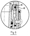
- Figure 5 shows, on an enlarged scale, the annular body 11 having its inner thread 13.
- Said annular body 11 is provided with an outer resilient ring element 12, arranged in an outer circumferential slot.
- the annular body 11 shown in figure 5 is further shown, by a top plan view, in figure 6.
- Said annular body 11 is herein split into individual annular segment like elements 11a, 11b, 11c and 11d. Said elements 11a, 11b, 11c and 11d have a respective inner thread 13. For holding said elements 11a, 11b, 11c, 11d of the annular body 11 resiliently coupled, said annular body 11 has an outer circumferential slot in which the O-Ring resilient element 12 is engaged.
- Figure 7 shows, by a cross-sectional view taken along the line VII-VII of figure 6, the annular body 11 and also clearly shows the circumferential resilient ring element 12, the individual segments 11b and 11d and the inner thread 13.
Landscapes
- Engineering & Computer Science (AREA)
- General Engineering & Computer Science (AREA)
- Mechanical Engineering (AREA)
- Quick-Acting Or Multi-Walled Pipe Joints (AREA)
- Non-Disconnectible Joints And Screw-Threaded Joints (AREA)
Abstract
Description
- The present invention relates to a quick coupling for threaded fittings.
- Quick couplings with threaded fittings are used, for example, at the end of an assembling line, where functional tests of the finished product are performed, by using a pressurized fluid.
- The above mentioned operations for testing and controlling apparatus and devices at the end of an assembling line are at present performed by hydraulic or pneumatic systems.
- Accordingly, it is necessary to connect a threaded end-piece, included in a quick coupling connected to a testing apparatus, with a fitting included in the device to be tested.
- To that end, said quick coupling was assembled, in prior methods for performing the testing operations, by assembling keys or tools designed for screwing on the threaded end-piece of the coupling, thereby assuring a required hydraulic or pneumatic sealing in feeding the fluid for performing the functional tests of the product.
- Thus, the requirement of using clamping keys or wrenches or specifically designed assembling tools required, in prior methods, a comparatively long time negatively affecting the testing operations, mostly in the case of simple apparatus the testing operation of which, by using a hydraulic or pneumatic fluid, would have required a less time.
- Accordingly, the main object of the present invention is to overcome the above mentioned drawbacks of the prior art, by providing a quick coupling, to be connected to a threaded end-piece or including a like connection contour, thereby allowing the coupling operations, respectively the uncoupling operations, to be manually performed without using specifically designed wrenches or tools, to allow the quick coupling to be also used for high pressures and flow rates, while preventing leakages from occurring during the coupling/uncoupling operating steps.
- Another object of the present invention is to provide such a quick coupling allowing a leakage free flow from the quick coupling to the connecting fitting.
- The above mentioned objects are achieved by a quick coupling for threaded end-pieces, comprising a fluid feeding fitting for feeding a pressurized hydraulic or pneumatic fluid passing through a tubular chamber extending for the overall length of the quick coupling, wherein said fitting comprises, at the end portion thereof provided for receiving said quick coupling, an annular body including annular segment like elements, wherein the individual elements forming said annular body are resiliently connected by a resilient ring element, and wherein on their outer circumference, respectively their inner circumference, said individual annular segment like elements comprise a thread or a like coupling contoured portion.
- Further advantages of the invention will become more apparent hereinafter from the following disclosure, the dependent claims and the accompanying drawings.
- The subject matter of the present invention will be disclosed in a more detailed manner hereinafter with reference to an embodiment thereof, given only by way of an example, and being shown in the accompanying drawings, where:
- Figure 1 is a cross-sectional view showing a tubular fitting with an inner thread to be connected to the quick coupling according to the present invention;
- Figure 2 shows the tubular fitting with the quick coupling engaging therein;
- Figure 3 shows a nipple having an outer thread and a quick coupling before the connection thereof;
- Figure 4 shows the threaded nipple with the quick coupling engaged therein;
- Figure 5 is a detail view showing a detail of the front end portion of the quick coupling to be connected;
- Figure 6 is a top plan view showing the body elements forming the threaded coupling element; and
- Figure 7 is a cross sectional view taken along the line VII-VII of figure 6 showing the coupling element.
- Figure 1 shows a
tubular fitting 1 having an inner threadedportion 2. - The
fitting 1 is provided for connection to a quick coupling which is generally indicated by thereference number 3. - To said
quick coupling 3 is supplied, through a feeding fitting 4, a pressurized hydraulic or pneumatic fluid passing, in the direction shown by the arrow (f) through atubular chamber 5 provided inside acentral pipe 6 extending for the overall length of thequick coupling 3. - As shown, the tubular chamber is not hindered by constructional inner elements, thereby allowing a free end unhindered flow (f) to pass therethrough.
- The
tubular body 6 is encompassed by atubular body 7 which is urged by apressing spring 8. - By radially extending
stems 9, saidtubular body 7 is operatively coupled to an outer actuatingring nut 10. - The free end portion 7a of the
tubular body 7 receives anannular body 11, comprising individual segment-like elements, which, against the counter-biassing of an outer, respectively innerresilient ring element 12, can be driven in a radial direction. - As shown in figure 1, the
annular body 11 has anouter thread 13 which can be connected during the connection of thequick coupling 3 with thetubular body 1, by engaging thethread 13 in the threadedportion 2. - Figure 1 shows that the
channel 5 of thetubular body 6 passes through the latter without being hindered and interrupted, thereby preventing any substantial flowrate loss from occurring in the pressurized fluid. - The
thread 13 of the bodies forming the interexchangeablecoupling ring element 11 may be freely selected, thereby allowing to choose anannular element 11 including, for example, a convention M 30 thread, or by replacing the ring element with anotherring 11, the latter may have an outer 3/4' gas thread; in this connection it should be apparent that it is also possible to use other types of threads, as well as other types of coupling contoured portions. - Advantageously, at the free end portion of the tubular body 14 is formed a circumferential groove 30 in which is engaged an O-
Ring 15, which, as thetubular fitting 1 andquick coupling 3 are assembled, will bear on thefront surface 16 of thetubular fitting 1, thereby providing a perfect tightly coupling relationship. - Figure 2 shows the
tubular fitting 1 coupled to the front portion of thequick coupling 3. - As shown, the annular gasket or
seal 15 perfectly bear on thefree surface 16 of thetubular fitting 1, thethread 13 of theannular body 11 being threaded with the threadedportion 2 of thetubular fitting 1. - The
spring 8 presses thetubular body 7 frontward in the direction (f). - Whilst figures 1 and 2 show a
fitting 1 having aninner thread 2, figure 3 shows atubular fitting 1 having anouter thread 2. - Accordingly, the
annular body 11 arranged inside thequick coupling 3 comprises in such a case, for its assembling, aninner thread 13 to be coupled to the outer thread or threadedportion 2 of thetubular fitting 1. - Figure 4 shows that, by coupling the
inner thread 13 of theannular body 11, it is possible to provide a connection with theouter thread 2 of thefitting 1. - Figure 5 shows, on an enlarged scale, the
annular body 11 having itsinner thread 13. Saidannular body 11 is provided with an outerresilient ring element 12, arranged in an outer circumferential slot. - The
annular body 11 shown in figure 5 is further shown, by a top plan view, in figure 6. - Said
annular body 11 is herein split into individual annular segment likeelements 11a, 11b, 11c and 11d. Saidelements inner thread 13. For holding saidelements annular body 11 resiliently coupled, saidannular body 11 has an outer circumferential slot in which the O-Ringresilient element 12 is engaged. - Figure 7 shows, by a cross-sectional view taken along the line VII-VII of figure 6, the
annular body 11 and also clearly shows the circumferentialresilient ring element 12, theindividual segments 11b and 11d and theinner thread 13.
Claims (6)
- A quick coupling for threaded end-pieces, comprising a feeding fitting for feeding therethrough a pressurized hydraulic or pneumatic fluid, passing through a tubular chamber extending from an overall length of said quick coupling, characterized in that an annular body (11) formed by a plurality of annular segment like elements (11a, 11b, 11c, 11d) is provided at an end portion facing said fitting (1) to receive said quick coupling (3), said individual elements (11a, 11 b, 11c, 11d) forming said annular body (11) being resiliently coupled by a resilient ring (12), and that on their outer, respectively inner, circumference, said individual annular segment-like elements (11a, 11b, 11c, 11d) comprise a thread (13) or like coupling contour.
- A quick coupling, according to claim 1, characterized in that the tubular chamber (5) formed in the central pipe (6) is free of hindering constructional elements.
- A quick coupling, according to claim 1, characterized in that said outer thread (13) of said annular body (11) is coupled, as the quick coupling (3) is assembled, to a threaded portion (2) of said tubular body.
- A quick coupling, according to claim 1, characterized in that said inner thread (13) of said annular body (11), is coupled, as said quick coupling (3) is assembled, to said thread of said tubular body.
- A quick coupling, according to claim 1, characterized in that said segment like elements (11a, 11b, 11c, 11d) forming said annular body (11) are interexchangeable and that the used annular elements (11a, 11b, 11c, 11d) have any desired type of threads or like contour.
- A quick coupling, according to claim 1, characterized in that said tubular body (14) has a free end portion including a circumferential groove (30) therein a sealing gasket (15) is engaged.
Applications Claiming Priority (1)
| Application Number | Priority Date | Filing Date | Title |
|---|---|---|---|
| IT001301A ITMI20061301A1 (en) | 2006-07-05 | 2006-07-05 | QUICK COUPLING FOR THREADED TERMINALS |
Publications (1)
| Publication Number | Publication Date |
|---|---|
| EP1876381A1 true EP1876381A1 (en) | 2008-01-09 |
Family
ID=38523426
Family Applications (1)
| Application Number | Title | Priority Date | Filing Date |
|---|---|---|---|
| EP07012678A Withdrawn EP1876381A1 (en) | 2006-07-05 | 2007-06-28 | Quick coupling for threaded fittings |
Country Status (7)
| Country | Link |
|---|---|
| US (1) | US20080007058A1 (en) |
| EP (1) | EP1876381A1 (en) |
| JP (1) | JP2008014495A (en) |
| KR (1) | KR20080004387A (en) |
| CN (1) | CN101101079A (en) |
| CA (1) | CA2593842A1 (en) |
| IT (1) | ITMI20061301A1 (en) |
Cited By (5)
| Publication number | Priority date | Publication date | Assignee | Title |
|---|---|---|---|---|
| EP2280208A1 (en) | 2009-07-28 | 2011-02-02 | Faster S.P.A. | Quick coupling for female threaded terminals or terminals with a similar connection profile |
| EP2320117A1 (en) | 2009-11-06 | 2011-05-11 | Faster S.P.A. | Quick coupling for threaded male terminals or terminals having a similar connecting profile |
| EP2428717A1 (en) | 2010-09-09 | 2012-03-14 | Faster S.p.A. | Gasket for quick couplings |
| WO2013175351A1 (en) | 2012-05-22 | 2013-11-28 | Polo S.R.L. | A rapid coupling for threaded or profiled terminals |
| CN112664691A (en) * | 2020-12-28 | 2021-04-16 | 宁波新佳行自动化工业有限公司 | Special multi-station pressure reducing valve for air compressor |
Families Citing this family (2)
| Publication number | Priority date | Publication date | Assignee | Title |
|---|---|---|---|---|
| US10190711B2 (en) * | 2015-12-07 | 2019-01-29 | Engineered Controls International, Llc | Low emission fluid coupler |
| CN111947021B (en) * | 2020-06-18 | 2025-04-22 | 国网河北省电力有限公司衡水供电分公司 | Sulfur hexafluoride gas filling detection and recovery device |
Citations (4)
| Publication number | Priority date | Publication date | Assignee | Title |
|---|---|---|---|---|
| EP0202592A1 (en) * | 1985-05-20 | 1986-11-26 | Erwin Weh | Pressure-tight plug coupling |
| EP0398849A2 (en) * | 1989-05-16 | 1990-11-22 | CRYOTECNAM DI GAROFALO GUIDO & C. s.a.s. | A rapid-coupling valve for transferring and bottling compressed gases for technical uses |
| DE19924394A1 (en) * | 1998-06-04 | 1999-12-09 | Fastest Inc | Coupling for high pressurized fluid line connection |
| EP1186822A1 (en) * | 2000-09-07 | 2002-03-13 | Gabriella Multinu | Quick-connect coupling |
Family Cites Families (6)
| Publication number | Priority date | Publication date | Assignee | Title |
|---|---|---|---|---|
| US3709528A (en) * | 1971-04-16 | 1973-01-09 | Foster Mfg Co Inc | Hose coupling |
| JPH0376958A (en) * | 1989-08-21 | 1991-04-02 | Shimizu Corp | Anchorage of bar-shaped body |
| JPH03121293U (en) * | 1990-03-26 | 1991-12-12 | ||
| JP3012159U (en) * | 1994-08-25 | 1995-06-13 | 株式会社日本ピスコ | Pipe fitting |
| JP4081872B2 (en) * | 1998-08-24 | 2008-04-30 | 株式会社Inax | Connection structure of tubular members |
| JP3988181B2 (en) * | 2002-03-15 | 2007-10-10 | 東海ゴム工業株式会社 | Tube fitting |
-
2006
- 2006-07-05 IT IT001301A patent/ITMI20061301A1/en unknown
-
2007
- 2007-06-28 EP EP07012678A patent/EP1876381A1/en not_active Withdrawn
- 2007-07-03 US US11/824,990 patent/US20080007058A1/en not_active Abandoned
- 2007-07-04 KR KR1020070066906A patent/KR20080004387A/en not_active Withdrawn
- 2007-07-05 CN CNA2007101421277A patent/CN101101079A/en active Pending
- 2007-07-05 JP JP2007177128A patent/JP2008014495A/en active Pending
- 2007-07-05 CA CA002593842A patent/CA2593842A1/en not_active Abandoned
Patent Citations (4)
| Publication number | Priority date | Publication date | Assignee | Title |
|---|---|---|---|---|
| EP0202592A1 (en) * | 1985-05-20 | 1986-11-26 | Erwin Weh | Pressure-tight plug coupling |
| EP0398849A2 (en) * | 1989-05-16 | 1990-11-22 | CRYOTECNAM DI GAROFALO GUIDO & C. s.a.s. | A rapid-coupling valve for transferring and bottling compressed gases for technical uses |
| DE19924394A1 (en) * | 1998-06-04 | 1999-12-09 | Fastest Inc | Coupling for high pressurized fluid line connection |
| EP1186822A1 (en) * | 2000-09-07 | 2002-03-13 | Gabriella Multinu | Quick-connect coupling |
Cited By (6)
| Publication number | Priority date | Publication date | Assignee | Title |
|---|---|---|---|---|
| EP2280208A1 (en) | 2009-07-28 | 2011-02-02 | Faster S.P.A. | Quick coupling for female threaded terminals or terminals with a similar connection profile |
| EP2320117A1 (en) | 2009-11-06 | 2011-05-11 | Faster S.P.A. | Quick coupling for threaded male terminals or terminals having a similar connecting profile |
| EP2428717A1 (en) | 2010-09-09 | 2012-03-14 | Faster S.p.A. | Gasket for quick couplings |
| WO2013175351A1 (en) | 2012-05-22 | 2013-11-28 | Polo S.R.L. | A rapid coupling for threaded or profiled terminals |
| CN112664691A (en) * | 2020-12-28 | 2021-04-16 | 宁波新佳行自动化工业有限公司 | Special multi-station pressure reducing valve for air compressor |
| CN112664691B (en) * | 2020-12-28 | 2023-05-16 | 宁波新佳行自动化工业有限公司 | Multi-station pressure reducing valve special for air compressor |
Also Published As
| Publication number | Publication date |
|---|---|
| KR20080004387A (en) | 2008-01-09 |
| US20080007058A1 (en) | 2008-01-10 |
| CN101101079A (en) | 2008-01-09 |
| CA2593842A1 (en) | 2008-01-05 |
| ITMI20061301A1 (en) | 2008-01-06 |
| JP2008014495A (en) | 2008-01-24 |
Similar Documents
| Publication | Publication Date | Title |
|---|---|---|
| EP1876381A1 (en) | Quick coupling for threaded fittings | |
| US10794521B2 (en) | Faucet with integrated push-to-connect fitting | |
| AU596318B2 (en) | Hose fitting | |
| EP2536970B1 (en) | Connection for valves | |
| CA2674166C (en) | Crimp evident seal | |
| US20130119659A1 (en) | Single axis push to connect conduit fitting | |
| US20080315582A1 (en) | High Pressure Energizable Tube Connector for a Well and Method of Energizing the Connector | |
| AU604973B2 (en) | Integral metal seal for hydraulic coupling | |
| US20120326439A1 (en) | Valve and Other Connections | |
| EP1878963A2 (en) | Quick coupling for connecting a pipe and a component, particularly a manifold or a flow control valve, for liquid or gas distribution systems | |
| US10480701B2 (en) | Pipeline insertion apparatus and method | |
| US20020014770A1 (en) | Flat-face quick coupling | |
| CN202992474U (en) | Fast connection device for air-tightness test of water-cooling radiator | |
| JPH0158398B2 (en) | ||
| US9163759B2 (en) | Fitting connection including compression nut with retainer | |
| US20200056734A1 (en) | No-Crimp Valve Assembly | |
| GB2160665A (en) | Test head for compressed gas cylinders | |
| US4375297A (en) | Quick coupling device | |
| US6702258B1 (en) | Universal ball valve assembly | |
| EP2547945B1 (en) | Sanitary clamp coupler with radial seal | |
| CA3002973C (en) | Threaded pipe connections and sockets for making the same in situ | |
| CN212265662U (en) | Valve spanner | |
| US8840150B2 (en) | Male fitting with actuating retaining feature | |
| RU101078U1 (en) | DEVICE FOR SEALING AN EXTERNAL SPACE | |
| NO337569B1 (en) | Device by clamping coupling |
Legal Events
| Date | Code | Title | Description |
|---|---|---|---|
| PUAI | Public reference made under article 153(3) epc to a published international application that has entered the european phase |
Free format text: ORIGINAL CODE: 0009012 |
|
| AK | Designated contracting states |
Kind code of ref document: A1 Designated state(s): AT BE BG CH CY CZ DE DK EE ES FI FR GB GR HU IE IS IT LI LT LU LV MC MT NL PL PT RO SE SI SK TR |
|
| AX | Request for extension of the european patent |
Extension state: AL BA HR MK YU |
|
| 17P | Request for examination filed |
Effective date: 20080228 |
|
| 17Q | First examination report despatched |
Effective date: 20080407 |
|
| AKX | Designation fees paid |
Designated state(s): AT BE BG CH CY CZ DE DK EE ES FI FR GB GR HU IE IS IT LI LT LU LV MC MT NL PL PT RO SE SI SK TR |
|
| STAA | Information on the status of an ep patent application or granted ep patent |
Free format text: STATUS: THE APPLICATION IS DEEMED TO BE WITHDRAWN |
|
| 18D | Application deemed to be withdrawn |
Effective date: 20080819 |