EP1876424B1 - Kodierer zur Verschiebungsbestimmung - Google Patents
Kodierer zur Verschiebungsbestimmung Download PDFInfo
- Publication number
- EP1876424B1 EP1876424B1 EP07012953A EP07012953A EP1876424B1 EP 1876424 B1 EP1876424 B1 EP 1876424B1 EP 07012953 A EP07012953 A EP 07012953A EP 07012953 A EP07012953 A EP 07012953A EP 1876424 B1 EP1876424 B1 EP 1876424B1
- Authority
- EP
- European Patent Office
- Prior art keywords
- code
- positional
- detected
- pseudo random
- error
- Prior art date
- Legal status (The legal status is an assumption and is not a legal conclusion. Google has not performed a legal analysis and makes no representation as to the accuracy of the status listed.)
- Ceased
Links
Images


Classifications
-
- G—PHYSICS
- G01—MEASURING; TESTING
- G01D—MEASURING NOT SPECIALLY ADAPTED FOR A SPECIFIC VARIABLE; ARRANGEMENTS FOR MEASURING TWO OR MORE VARIABLES NOT COVERED IN A SINGLE OTHER SUBCLASS; TARIFF METERING APPARATUS; MEASURING OR TESTING NOT OTHERWISE PROVIDED FOR
- G01D5/00—Mechanical means for transferring the output of a sensing member; Means for converting the output of a sensing member to another variable where the form or nature of the sensing member does not constrain the means for converting; Transducers not specially adapted for a specific variable
- G01D5/26—Mechanical means for transferring the output of a sensing member; Means for converting the output of a sensing member to another variable where the form or nature of the sensing member does not constrain the means for converting; Transducers not specially adapted for a specific variable characterised by optical transfer means, i.e. using infrared, visible, or ultraviolet light
- G01D5/32—Mechanical means for transferring the output of a sensing member; Means for converting the output of a sensing member to another variable where the form or nature of the sensing member does not constrain the means for converting; Transducers not specially adapted for a specific variable characterised by optical transfer means, i.e. using infrared, visible, or ultraviolet light with attenuation or whole or partial obturation of beams of light
- G01D5/34—Mechanical means for transferring the output of a sensing member; Means for converting the output of a sensing member to another variable where the form or nature of the sensing member does not constrain the means for converting; Transducers not specially adapted for a specific variable characterised by optical transfer means, i.e. using infrared, visible, or ultraviolet light with attenuation or whole or partial obturation of beams of light the beams of light being detected by photocells
- G01D5/347—Mechanical means for transferring the output of a sensing member; Means for converting the output of a sensing member to another variable where the form or nature of the sensing member does not constrain the means for converting; Transducers not specially adapted for a specific variable characterised by optical transfer means, i.e. using infrared, visible, or ultraviolet light with attenuation or whole or partial obturation of beams of light the beams of light being detected by photocells using displacement encoding scales
- G01D5/34776—Absolute encoders with analogue or digital scales
- G01D5/34792—Absolute encoders with analogue or digital scales with only digital scales or both digital and incremental scales
Definitions
- the present invention relates to a displacement detecting encoder and, in particular, to a displacement detecting encoder which is appropriately applicable to an absolute measurement type encoder using a pseudo random code and able to correct errors by using a minimum code without adding a redundant code.
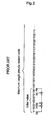
- a displacement detecting encoder (also referred to as an ABS encoder) for detecting an absolute (ABS) position by using a scale in which a grating corresponding to a pseudo random code as shown in the case of Maximum Length in Fig. 1 is formed as a detection pattern.
- Patent Document 1 Japanese Published Unexamined Patent Application No. 2001-296145 (Patent Document 1) has disclosed that detection codes read from a scale containing a redundant pattern are sequentially shifted to calculate absolute position data, and a possible occurrence of a reading error is judged with reference to whether each of the thus shifted and calculated absolute position data is continued.
- Patent Document 2 Japanese Published Unexamined Patent Application No. 2004-117360 (Patent Document 2) has also disclosed that where there is found a decreased difference (corresponding to contrast of transmitted light) in analog scanning signals generated by scanning an interpolatory constituted region due to dirt and the like, such a result is not subjected to calculation.
- Patent Document 1 not only needs to add a redundant pattern but also needs to calculate absolute position data, while shifting detected code, thus resulting in a greater calculation load.
- Patent Document 2 makes a judgment by referring only to the contrast of transmitted light, thus resulting in a lower accuracy of detecting errors.
- Patent Documents 1 and 2 have a problem of only being able to detect an error but not being able to correct the error.
- EP 1 403 623 A1 describes method for determining an absolute position. According to the method for determining an absolute position a code is redundantly scanned by detecting further bits in addition to the code word necessary for absolute determining the position. All bits derived from scanning are monitored with regard to their reliability and a error indication is associated with a bit that has been determined to be unreliable. During decoding the bits with an error indication remain unused.
- US 4,733,069 describes position encoder using a laser scan beam.
- This document provides a position encoder comprising a laser scanning type encoding member on which data tracks aligned at equal intervals in a mowing direction of a part to be position-measured.
- a sensor with a single laser beam deflectable along the track is used for reading the position data. High resolution is obtained since it depends upon recorded pitch of tracks. Many data can be recorded on each track, including error correction code for the position code. It improves reliability of the encoder.
- Fig. 1 is a view showing an example of an Maximum Length pseudo random code.
- Fig. 2 is a view showing a method for generating the Maximum Length pseudo random code.
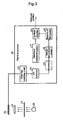
- Fig. 3 is a view showing an embodiment of the apparatus for executing the present invention.
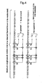
- Fig. 4 is a view showing one method for recalculating the pseudo random code with reference to the present invention.
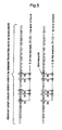
- Fig. 5 is a view showing another method.
- Fig. 6 is a view showing a method for correcting a detection error.
- Fig. 7 is a view showing an exemplified variation of the apparatus.
- pseudo random number P0 is defined by the following formula.
- P ⁇ 0 D ⁇ 0 xor D ⁇ 1 xor D ⁇ 2 xor D ⁇ 3
- D0 is data of tap position 1
- D1 is data of tap position 5
- D2 is data of tap position 7
- D3 is data of tap position 14.
- a light emitting element 20 shown in Fig. 3 is used to illuminate the scale 10, and transmitted light is detected by a light receiving element array 24 capable of receiving light for 58 digits, for example, and the result is calculated by a signal processor 30 to obtain an absolute position.
- the signal processor 30 is constituted with a noise filter amplifying circuit 32 in which, for example, signals obtained by sweeping output signals of a light receiving element array 24 along a direction of measurement axis are cut for high frequency noise by using a low pass filter and also amplified by a predetermined gain, an A/D conversion circuit 34 for converting analog signals output from the noise filter amplifying circuit 32 to digital signals for signal processing, a binary circuit 36 for binarizing an output of the A/D conversion circuit 34 by a predetermined threshold value, a detection/correction circuit 38 for detecting and correcting an error by using the formula (1) for generating a pseudo random code according to the present invention, an ABS position detection circuit 40 for detecting an ABS position by a correlation calculation of scale pattern design values and detected signals, an incremental position detection circuit 42 for detecting an incremental position by generating a 2-phase sine wave of 90-degree phase difference from a 4-phase sine wave of 90-degree phase difference (not illustrated) and making an arc tangent calculation for the purpose of interpolating the ABS position to
- a correlation function used in making a correlation calculation of the ABS position detection circuit 40 is subjected to either a difference calculus method or a multiplication method.
- a method for generating a pseudo random code is used to recalculate with respect to the detected pseudo random code.
- bits of a frame are recalculated, for example, upon detection of a 58-digit Maximum Length pseudo random code, data D0, D1, D2 and D3 respectively covering the tap positions 1, 5, 7, 14 are used to compare data calculated on the basis of the formula (1) with actual data P0 on the 17th digit.
- an error detecting bit E is defined with reference to the formula (1) as follows.
- E D ⁇ 0 xor D ⁇ 1 xor D ⁇ 2 xor D ⁇ 3 xor P ⁇ 0
- the error detecting bits of E0 to E4 are defined with respect to the bits to be recalculated in Fig. 6 .
- the bit to be recalculated Px is corrected for the value. In this case, the bit to be recalculated Px in the drawing is corrected from 0 to 1.
- an error is detected and corrected on the basis of calculation results obtained by using the above calculation formula.
- a combination of detection bits at each position is calculated in advance by using the above formula, and the combination of detection bits and positional information are given as a set, which may be stored in a corresponding table. Then, the thus detected detection position bits are used to detect an error with reference to the corresponding table, by which the necessity for making a calculation processing can be eliminated to speed up error detection and correction.
- the present invention is applied to a transmissive type scale.
- the present invention is not restricted thereto, and is similarly applicable to a reflective type scale as shown in Fig. 7 .
- Types of pseudo random codes are not restricted to Maximum Length.
- the number of rows of initial values, tap positions and number of digits of detection codes are not restricted to those described in the embodiments.
Landscapes
- Physics & Mathematics (AREA)
- General Physics & Mathematics (AREA)
- Transmission And Conversion Of Sensor Element Output (AREA)
- Optical Transform (AREA)
Claims (10)
- Verschiebungserfassungs-Kodierer, der enthält:eine Skala (10), die einen Positionscode aufweist, der Positionsinformationen beinhaltet, wobei der Positionscode als ein Muster auf der Skala angeordnet ist;einen Erfassungsabschnitt (24), der so angeordnet ist, dass er eine relative Bewegung in Bezug auf die Skala (10) ausführt und wenigstens einen Teil des als ein Muster auf der Skala angeordneten Positionscodes erfasst, um so einen erfassten Positionscode bereitzustellen;einen Verarbeitungsabschnitt, der umfasst:eine Positionscode-Erzeugungseinrichtung (38), die so eingerichtet ist, dass sie den erfassten Positionscode erzeugt, wobei der erfasste Positionscode mit dem gleichen Algorithmus bewertet wird, der zum Erzeugen des Skalenmusters verwendet wird, um das Vorhandensein oder Nichtvorhandensein fehlerhafter Informationen zu erfassen,
wobeider Positionscode ein Pseudozufallscode ist, der Pseudozufallscode unter Verwendung eines Ausgangswertes und einer Formel erzeugt wird, wobei eine Pseudozufallszahl des Codes hergeleitet wird, indem die Formel auf zuvor hergeleitete Pseudozufallszahlen oder auf den Anfangswert angewendet wird; und wobeieine Fehlererfassungseinrichtung so eingerichtet ist, dass sie ein Fehlererfassungs-Bit E erfasst, wobei das Fehlererfassungs-Bit auf einer Exklusiv-ODER-Beziehung basiert. - Verschiebungserfassungs-Kodierer nach Anspruch 1, wobei die Exklusiv-ODER-Beziehung auf einen Wert angewendet wird, der hergeleitet wird, indem die Formel auf eine aktuelle Position innerhalb des erfassten Positionscodes und auf eine Pseudo-Zufallszahl P0 angewendet wird, die unter Verwendung der Formel aus dem erfassten Positionscode der aktuellen Position hergeleitet wird.
- Verschiebungserfassungs-Kodierer nach Anspruch 2, wobei
das Fehlererfassungs-Bit E aus der Beziehung
E = D0 xor D1 xor D2 xor D3 xor P0 hergeleitet wird, wobei
D0, D1, D2, D3 Datenwerte an Tab-Positionen in dem aktuellen erfassten Pseudozufallscode darstellen, und
P0 = D0 xor D1 xor D2 xor D3, wobei P0 eine Pseudozufallszahl ist, die aus dem aktuellen erfassten Pseudozufallscode hergeleitet wird,
wobei E = 1 einen Fehler in dem erfassten Positionscode anzeigt. - Verschiebungserfassungs-Kodierer nach Anspruch 1, wobei
eine Vielzahl der Fehlererfassungs-Bits definiert sind und ein Fehlermarkierungsbit unter Bezugnahme auf Werte der Fehlererfassungs-Bits spezifiziert wird. - Verschiebungserfassungs-Kodierer nach Anspruch 1, wobei
die Positionscode-Erzeugungseinrichtung (38) mit einer entsprechenden Tabelle von Positionsinformationen und Positionscodes versehen ist. - Verschiebungserfassungs-Kodierer nach einem der Ansprüche 1 bis 5, wobei
auf Basis des Ergebnisses, mit dem das Vorhandensein oder Nichtvorhandensein der fehlerhaften Informationen erfasst wird, die erfassten fehlerhaften Informationen beseitigt werden. - Verschiebungserfassungs-Kodierer nach einem der Ansprüche 1 bis 5, wobei
auf Basis des Ergebnisses, mit dem das Vorhandensein oder Nichtvorhandensein der fehlerhaften Informationen erfasst wird, die erfassten fehlerhaften Informationen korrigiert werden. - Verschiebungserfassungs-Kodierer nach einem der Ansprüche 1 bis 7, der zusätzlich mit einer inkrementalen Positionserfassungseinrichtung (42) versehen ist, mit der durch den Positionscode erfasste Positionsinformationen interpoliert werden, um die Auflösung zu verbessern.
- Verfahren zur Fehlererfassung, das für einen Verschiebungserfassungs-Kodierer geeignet ist, wobei das Verfahren umfasst:Anordnen eines Positionscodes, der Positionsinformationen enthält, als ein Muster auf einer Skala (10);Verwenden eines Erfassungsabschnitts (24), der so angeordnet ist, dass er eine relative Bewegung in Bezug auf die Skala (10) ausführt und wenigstens einen Teil des als ein Muster auf der Skala angeordneten Positionscodes erfasst, um so einen erfassten Positionscode bereitzustellen; undVerwenden einer Positionscode-Erzeugungseinrichtung (38), um den erfassten Code zu erzeugen, wobei der erfasste Positionscode mit dem gleichen Algorithmus bewertet wird, der zum Erzeugen des Skalenmusters verwendet wird, um das Vorhandensein oder Nichtvorhandensein fehlerhafter Informationen zu erfassen, wobeider Positionscode ein Pseudozufallscode ist, der Pseudozufallscode unter Verwendung eines Ausgangswertes und einer Formel erzeugt wird, wobei eine Pseudozufallszahl des Codes hergeleitet wird, indem die Formel auf zuvor hergeleitete Pseudozufallszahlen oder auf den Anfangswert angewendet wird; undVerwenden einer Fehlererfassungseinrichtung zum Erfassen eines Fehlererfassungs-Bits E, wobei das Fehlererfassungs-Bit auf einer Exklusiv-ODER-Beziehung basiert.
- Verfahren nach Anspruch 9, wobei die Exklusiv-ODER-Beziehung auf einen Wert angewendet wird, der hergeleitet wird, indem die Formel auf eine aktuelle Position innerhalb des erfassten Positionscodes und auf eine Pseudo-Zufallszahl P0 angewendet wird, die unter Verwendung der Formel aus dem erfassten Positionscode der aktuellen Position hergeleitet wird.
Applications Claiming Priority (1)
| Application Number | Priority Date | Filing Date | Title |
|---|---|---|---|
| JP2006183560A JP5021244B2 (ja) | 2006-07-03 | 2006-07-03 | 変位検出エンコーダ |
Publications (3)
| Publication Number | Publication Date |
|---|---|
| EP1876424A2 EP1876424A2 (de) | 2008-01-09 |
| EP1876424A3 EP1876424A3 (de) | 2008-05-14 |
| EP1876424B1 true EP1876424B1 (de) | 2010-06-16 |
Family
ID=38611087
Family Applications (1)
| Application Number | Title | Priority Date | Filing Date |
|---|---|---|---|
| EP07012953A Ceased EP1876424B1 (de) | 2006-07-03 | 2007-07-02 | Kodierer zur Verschiebungsbestimmung |
Country Status (5)
| Country | Link |
|---|---|
| US (1) | US7565256B2 (de) |
| EP (1) | EP1876424B1 (de) |
| JP (1) | JP5021244B2 (de) |
| CN (1) | CN101101223B (de) |
| DE (1) | DE602007007157D1 (de) |
Families Citing this family (11)
| Publication number | Priority date | Publication date | Assignee | Title |
|---|---|---|---|---|
| JP5203024B2 (ja) | 2008-04-15 | 2013-06-05 | 株式会社ミツトヨ | 絶対位置測長型エンコーダ |
| CN101592468B (zh) * | 2009-06-25 | 2011-08-17 | 广州中国科学院工业技术研究院 | 伪随机码位移传感器的环形寻址方法及其系统 |
| JP2011058988A (ja) | 2009-09-11 | 2011-03-24 | Mitsutoyo Corp | 変位検出装置、変位検出方法及び変位検出プログラム |
| CN101782405B (zh) * | 2010-01-26 | 2013-04-10 | 中国科学院光电技术研究所 | 一种基于伪随机编码位移传感器的硬件实时校验方法及其系统 |
| CN103528612B (zh) * | 2013-10-26 | 2017-01-11 | 连云港杰瑞电子有限公司 | 一种提高绝对式旋转编码器分辨率的方法 |
| JP6320149B2 (ja) * | 2014-04-21 | 2018-05-09 | キヤノン株式会社 | アブソリュートエンコーダ |
| JP6634249B2 (ja) * | 2015-09-14 | 2020-01-22 | 株式会社ミツトヨ | 絶対位置検出型光電式エンコーダ |
| US10249116B1 (en) * | 2018-03-12 | 2019-04-02 | Mapsted Corp. | Method and system for mobile device localization-based access |
| JP7252809B2 (ja) * | 2019-03-28 | 2023-04-05 | 株式会社ミツトヨ | 光電式エンコーダおよび光電式エンコーダにおける演算方法 |
| US12052801B2 (en) | 2019-08-06 | 2024-07-30 | Eberspächer Catem Gmbh & Co. Kg | PTC electric heating device |
| CN110954129A (zh) * | 2019-12-19 | 2020-04-03 | 北京猎户星空科技有限公司 | 一种里程计数据的确定方法、装置、设备及介质 |
Family Cites Families (13)
| Publication number | Priority date | Publication date | Assignee | Title |
|---|---|---|---|---|
| JPS56153212A (en) * | 1980-04-30 | 1981-11-27 | Toshiba Corp | Encoder |
| US4733069A (en) | 1986-02-14 | 1988-03-22 | Optec Co., Ltd. | Position encoder using a laser scan beam |
| JPS63247615A (ja) * | 1987-04-02 | 1988-10-14 | Matsushita Electric Ind Co Ltd | 位置検出方法及びその装置 |
| JPH04131713A (ja) * | 1990-09-25 | 1992-05-06 | Nikon Corp | センサ続み誤りの検出および訂正が可能な1トラック型アブソリュート・エンコーダ |
| US5418362A (en) | 1993-05-27 | 1995-05-23 | Lusby; Brett L. | Encoder for determining absolute linear and rotational positions |
| DE69622297T2 (de) * | 1995-02-21 | 2002-11-21 | Canon K.K., Tokio/Tokyo | Vorrichtung zur Bestimmung einer Verschiebung und deren Verwendung in einer Einrichtung zur Antriebsregelung |
| JP4223195B2 (ja) * | 2000-02-10 | 2009-02-12 | オークマ株式会社 | アブソリュートエンコーダ |
| US6642884B2 (en) * | 2000-05-08 | 2003-11-04 | Sigtec Navigation Pty Ltd. | Satellite-based positioning system receiver for weak signal operation |
| JP4521125B2 (ja) * | 2001-01-30 | 2010-08-11 | 株式会社 ソキア・トプコン | アブソリュートエンコーダ用ディスク |
| US6686585B2 (en) * | 2001-09-19 | 2004-02-03 | Microe Systems Corporation | Position encoder with scale calibration |
| DE10244547B4 (de) | 2002-09-25 | 2010-11-11 | Dr. Johannes Heidenhain Gmbh | Verfahren und Positionsmesseinrichtung zur Bestimmung einer absoluten Position |
| US7053362B2 (en) * | 2003-05-02 | 2006-05-30 | Mitutoyo Corporation | Absolute position miniature grating encoder readhead using fiber optic receiver channels |
| JP4586677B2 (ja) * | 2005-08-24 | 2010-11-24 | 富士ゼロックス株式会社 | 画像形成装置 |
-
2006
- 2006-07-03 JP JP2006183560A patent/JP5021244B2/ja not_active Expired - Fee Related
-
2007
- 2007-06-25 US US11/819,093 patent/US7565256B2/en active Active
- 2007-06-29 CN CN2007101263305A patent/CN101101223B/zh not_active Expired - Fee Related
- 2007-07-02 EP EP07012953A patent/EP1876424B1/de not_active Ceased
- 2007-07-02 DE DE602007007157T patent/DE602007007157D1/de active Active
Also Published As
| Publication number | Publication date |
|---|---|
| JP2008014665A (ja) | 2008-01-24 |
| JP5021244B2 (ja) | 2012-09-05 |
| EP1876424A3 (de) | 2008-05-14 |
| CN101101223A (zh) | 2008-01-09 |
| DE602007007157D1 (de) | 2010-07-29 |
| US20080015805A1 (en) | 2008-01-17 |
| US7565256B2 (en) | 2009-07-21 |
| CN101101223B (zh) | 2012-04-11 |
| EP1876424A2 (de) | 2008-01-09 |
Similar Documents
| Publication | Publication Date | Title |
|---|---|---|
| EP1876424B1 (de) | Kodierer zur Verschiebungsbestimmung | |
| EP3480564B1 (de) | Positionsmessungscodierer und verfahren zum betrieb | |
| EP1619476B1 (de) | Codierer und Signalanpassungsverfahren dafür | |
| US8110792B2 (en) | Absolute position length measurement type encoder | |
| JP5079644B2 (ja) | 位置測定装置 | |
| US7013575B2 (en) | Position measuring device | |
| JP5011201B2 (ja) | 絶対位置測長型エンコーダ | |
| US20050236560A1 (en) | Absolute encoder | |
| JP4846331B2 (ja) | 光電式エンコーダ、及び、そのスケール | |
| EP2878928B1 (de) | Absolutcodierer, Signalverarbeitungsverfahren, Programm, Ansteuerungsvorrichtung und Industriemaschine | |
| EP2110645B1 (de) | Absolutpositionscodierer vom Längsmessungstyp | |
| US20110208475A1 (en) | Absolute angle coding and angle measuring device | |
| US20110218761A1 (en) | Absolute position measuring device | |
| US6563443B2 (en) | Method and device for absolute position determination | |
| JP4223195B2 (ja) | アブソリュートエンコーダ | |
| JP2015137955A (ja) | アブソリュートエンコーダ | |
| JP4885630B2 (ja) | 二次元エンコーダ、及び、そのスケール | |
| EP2312273A2 (de) | Verschiebungsdetektor, Verschiebungsdetektionsverfahren und Computerprogrammprodukt | |
| US9322675B2 (en) | Absolute encoder and method of obtaining absolute position by a plurality of quantized data based on a plurality of extrema | |
| JP2754635B2 (ja) | アブソリュートエンコーダ | |
| JPH0335111A (ja) | 絶対位置検出装置 | |
| JPH07270182A (ja) | アブソリュートエンコーダ | |
| US12078517B2 (en) | Encoder including moving plate, irradiator, light receiver and determination part to specify error position | |
| US20260071897A1 (en) | Encoder apparatus | |
| CN113447051B (zh) | 单码道绝对式位置测量装置 |
Legal Events
| Date | Code | Title | Description |
|---|---|---|---|
| PUAI | Public reference made under article 153(3) epc to a published international application that has entered the european phase |
Free format text: ORIGINAL CODE: 0009012 |
|
| AK | Designated contracting states |
Kind code of ref document: A2 Designated state(s): AT BE BG CH CY CZ DE DK EE ES FI FR GB GR HU IE IS IT LI LT LU LV MC MT NL PL PT RO SE SI SK TR |
|
| AX | Request for extension of the european patent |
Extension state: AL BA HR MK YU |
|
| PUAL | Search report despatched |
Free format text: ORIGINAL CODE: 0009013 |
|
| AK | Designated contracting states |
Kind code of ref document: A3 Designated state(s): AT BE BG CH CY CZ DE DK EE ES FI FR GB GR HU IE IS IT LI LT LU LV MC MT NL PL PT RO SE SI SK TR |
|
| AX | Request for extension of the european patent |
Extension state: AL BA HR MK RS |
|
| 17P | Request for examination filed |
Effective date: 20081113 |
|
| 17Q | First examination report despatched |
Effective date: 20081210 |
|
| AKX | Designation fees paid |
Designated state(s): DE FR GB |
|
| GRAP | Despatch of communication of intention to grant a patent |
Free format text: ORIGINAL CODE: EPIDOSNIGR1 |
|
| GRAS | Grant fee paid |
Free format text: ORIGINAL CODE: EPIDOSNIGR3 |
|
| GRAA | (expected) grant |
Free format text: ORIGINAL CODE: 0009210 |
|
| RAP1 | Party data changed (applicant data changed or rights of an application transferred) |
Owner name: MITUTOYO CORPORATION |
|
| AK | Designated contracting states |
Kind code of ref document: B1 Designated state(s): DE FR GB |
|
| REF | Corresponds to: |
Ref document number: 602007007157 Country of ref document: DE Date of ref document: 20100729 Kind code of ref document: P |
|
| PLBE | No opposition filed within time limit |
Free format text: ORIGINAL CODE: 0009261 |
|
| STAA | Information on the status of an ep patent application or granted ep patent |
Free format text: STATUS: NO OPPOSITION FILED WITHIN TIME LIMIT |
|
| 26N | No opposition filed |
Effective date: 20110317 |
|
| REG | Reference to a national code |
Ref country code: DE Ref legal event code: R097 Ref document number: 602007007157 Country of ref document: DE Effective date: 20110316 |
|
| REG | Reference to a national code |
Ref country code: FR Ref legal event code: PLFP Year of fee payment: 10 |
|
| REG | Reference to a national code |
Ref country code: FR Ref legal event code: PLFP Year of fee payment: 11 |
|
| REG | Reference to a national code |
Ref country code: FR Ref legal event code: PLFP Year of fee payment: 12 |
|
| PGFP | Annual fee paid to national office [announced via postgrant information from national office to epo] |
Ref country code: GB Payment date: 20230720 Year of fee payment: 17 |
|
| PGFP | Annual fee paid to national office [announced via postgrant information from national office to epo] |
Ref country code: FR Payment date: 20230725 Year of fee payment: 17 Ref country code: DE Payment date: 20230719 Year of fee payment: 17 |
|
| REG | Reference to a national code |
Ref country code: DE Ref legal event code: R119 Ref document number: 602007007157 Country of ref document: DE |
|
| GBPC | Gb: european patent ceased through non-payment of renewal fee |
Effective date: 20240702 |
|
| PG25 | Lapsed in a contracting state [announced via postgrant information from national office to epo] |
Ref country code: DE Free format text: LAPSE BECAUSE OF NON-PAYMENT OF DUE FEES Effective date: 20250201 |
|
| PG25 | Lapsed in a contracting state [announced via postgrant information from national office to epo] |
Ref country code: FR Free format text: LAPSE BECAUSE OF NON-PAYMENT OF DUE FEES Effective date: 20240731 |
|
| PG25 | Lapsed in a contracting state [announced via postgrant information from national office to epo] |
Ref country code: GB Free format text: LAPSE BECAUSE OF NON-PAYMENT OF DUE FEES Effective date: 20240702 |