EP1876616A2 - Reset device for limit switch and limit switch incorporating such device - Google Patents
Reset device for limit switch and limit switch incorporating such device Download PDFInfo
- Publication number
- EP1876616A2 EP1876616A2 EP07012965A EP07012965A EP1876616A2 EP 1876616 A2 EP1876616 A2 EP 1876616A2 EP 07012965 A EP07012965 A EP 07012965A EP 07012965 A EP07012965 A EP 07012965A EP 1876616 A2 EP1876616 A2 EP 1876616A2
- Authority
- EP
- European Patent Office
- Prior art keywords
- reset
- switch
- housing
- bracket
- reset device
- Prior art date
- Legal status (The legal status is an assumption and is not a legal conclusion. Google has not performed a legal analysis and makes no representation as to the accuracy of the status listed.)
- Granted
Links
Images



Classifications
-
- H—ELECTRICITY
- H01—ELECTRIC ELEMENTS
- H01H—ELECTRIC SWITCHES; RELAYS; SELECTORS; EMERGENCY PROTECTIVE DEVICES
- H01H11/00—Apparatus or processes specially adapted for the manufacture of electric switches
- H01H11/0006—Apparatus or processes specially adapted for the manufacture of electric switches for converting electric switches
- H01H11/0018—Apparatus or processes specially adapted for the manufacture of electric switches for converting electric switches for allowing different operating parts
-
- H—ELECTRICITY
- H01—ELECTRIC ELEMENTS
- H01H—ELECTRIC SWITCHES; RELAYS; SELECTORS; EMERGENCY PROTECTIVE DEVICES
- H01H13/00—Switches having rectilinearly-movable operating part or parts adapted for pushing or pulling in one direction only, e.g. push-button switch
- H01H13/68—Switches having rectilinearly-movable operating part or parts adapted for pushing or pulling in one direction only, e.g. push-button switch having two operating members, one for opening and one for closing the same set of contacts
-
- H—ELECTRICITY
- H01—ELECTRIC ELEMENTS
- H01H—ELECTRIC SWITCHES; RELAYS; SELECTORS; EMERGENCY PROTECTIVE DEVICES
- H01H21/00—Switches operated by an operating part in the form of a pivotable member acted upon directly by a solid body, e.g. by a hand
- H01H21/02—Details
- H01H21/18—Movable parts; Contacts mounted thereon
- H01H21/22—Operating parts, e.g. handle
- H01H21/24—Operating parts, e.g. handle biased to return to normal position upon removal of operating force
- H01H21/28—Operating parts, e.g. handle biased to return to normal position upon removal of operating force adapted for actuation at a limit or other predetermined position in the path of a body, the relative movement of switch and body being primarily for a purpose other than the actuation of the switch, e.g. door switch, limit switch, floor-levelling switch of a lift
-
- H—ELECTRICITY
- H01—ELECTRIC ELEMENTS
- H01H—ELECTRIC SWITCHES; RELAYS; SELECTORS; EMERGENCY PROTECTIVE DEVICES
- H01H3/00—Mechanisms for operating contacts
- H01H3/02—Operating parts, i.e. for operating driving mechanism by a mechanical force external to the switch
- H01H3/022—Emergency operating parts, e.g. for stop-switch in dangerous conditions
- H01H2003/024—Resetting of bistable emergency operating part by pulling it
-
- H—ELECTRICITY
- H01—ELECTRIC ELEMENTS
- H01H—ELECTRIC SWITCHES; RELAYS; SELECTORS; EMERGENCY PROTECTIVE DEVICES
- H01H21/00—Switches operated by an operating part in the form of a pivotable member acted upon directly by a solid body, e.g. by a hand
- H01H21/02—Details
- H01H21/18—Movable parts; Contacts mounted thereon
- H01H21/22—Operating parts, e.g. handle
- H01H21/24—Operating parts, e.g. handle biased to return to normal position upon removal of operating force
- H01H21/28—Operating parts, e.g. handle biased to return to normal position upon removal of operating force adapted for actuation at a limit or other predetermined position in the path of a body, the relative movement of switch and body being primarily for a purpose other than the actuation of the switch, e.g. door switch, limit switch, floor-levelling switch of a lift
- H01H2021/287—Operating parts, e.g. handle biased to return to normal position upon removal of operating force adapted for actuation at a limit or other predetermined position in the path of a body, the relative movement of switch and body being primarily for a purpose other than the actuation of the switch, e.g. door switch, limit switch, floor-levelling switch of a lift with adjustable head, e.g. the actuator head can have different positions in relation to the limit switch itself
-
- H—ELECTRICITY
- H01—ELECTRIC ELEMENTS
- H01H—ELECTRIC SWITCHES; RELAYS; SELECTORS; EMERGENCY PROTECTIVE DEVICES
- H01H3/00—Mechanisms for operating contacts
- H01H3/02—Operating parts, i.e. for operating driving mechanism by a mechanical force external to the switch
- H01H3/20—Operating parts, i.e. for operating driving mechanism by a mechanical force external to the switch wherein an auxiliary movement thereof, or of an attachment thereto, is necessary before the main movement is possible or effective, e.g. for unlatching, for coupling
Definitions
- the present invention generally finds application in the field of safety electric devices and relates to a reset device for use with a limit switch, and to a limit switch incorporating such device.
- the switch is particularly designed to be used for overtravel detection in automatic systems such as automatic processing lines, elevators, hoists or the like.
- switches are particularly designed to be used in control systems for elevators or hoists and have the purpose of monitoring overtravels or abnormal conditions to cause the car to stop whenever the actual travel exceeds the maximum preset travel.
- Commonly available position switches have a case for holding one or more pairs of electric contacts connected to the power and signal circuits of the system and a button- or lever- actuator, operating on the contacts to cause the power circuit to open and the system to stop in emergency situations.
- the actuator is housed in a head which is mounted upon the contact holder, generally in a removable manner.
- the switches are additionally provided with a reset device, which is integrated in the head and actuated by the actuator, and has the purpose of preventing accidental restoration of power in the main circuit without action by an operator.
- the head, with the reset device integrated therein shall be also replaced.
- a further drawback of prior art known solutions is that the actuator has a rather slow operation and does not consequently ensure simultaneity between triggering of the reset device and opening of contacts.
- the reset device is usually triggered after an actuator travel which is significantly longer than the travel required for contact opening.
- a similar reset device is provided, for instance, in a limit switch sold by Telemecanique Electrique in which the enclosure, the head and the device are formed separately to allow coupling of the various parts with different orientations and in a modular manner.
- the particular configuration of the reset device does not obviate the above mentioned drawbacks of the switch in which it is incorporated, associated to the impossibility of ensuring that the reset is triggered at the same time as the switch is turned off.
- the object of the present invention is to obviate the above drawbacks, by providing a reset device for limit switches that is highly efficient and relatively cost-effective.
- a particular object is to provide a reset device that can be triggered at the same time as contacts are opened and can be also modularly and interchangeably fitted onto the head and case of any limit switch, while maintaining its resetting function unchanged and thereby increasing the safety of the plant in which it is mounted.
- a further object is to provide a reset device that can be oriented relative to the head and case of the switch for which it is designed, thereby improving the flexibility of use for the whole switch.
- Another object is to provide a limit switch in which the electric contacts arranged therein are all triggered substantially at the same time.
- a reset device as defined in claim 1, to be coupled to a limit switch having a case designed to contain at least one pair of electric contacts and a control head having internally thereof actuator means for mutually moving the contacts, wherein the device comprises a modular housing with an upper peripheral edge, a bottom wall and side walls defining a longitudinal axis, interface means associated to said housing for removable connection both to the head and to the case of the limit switch, reset means at least partly contained in said housing for controlled activation and deactivation of the limit switch.
- the device is characterized in that the reset means have such a shape as to interact with the actuator means of the switch to promote positive opening of the electric contacts substantially at the same time as the switch is activated/deactivated.
- the reset device will be triggered substantially at the same time as the electric contacts are opened to ensure proper operation both of the device and the switch.
- the modular nature of the device allows use of the latter with a wide range of limit switches without the need of providing special reset means for each switch and while maintaining its functions unchanged.
- the interface means may have one or more suitably shaped protrusions both on the bottom wall and along the upper peripheral edge of the housing, which are designed for engagement in corresponding recesses of complementary shape on the case and the head respectively of the switch with which the device is associated.
- the housing may have a generally prismatic shape, substantially symmetric with respect to the longitudinal axis to allow orientation and selective coupling thereof with the switch in substantially 90° spaced angular positions.
- both the reset device and the switch in which it is provided provide a high flexibility of use, by adapting the mutual positions of the various parts of the switch to the structural features of the machine and system served thereby.
- the invention relates to a limit switch comprising a reset device as defined in any one of claims 1 to 15, and interposed between the head and the case of the switch.
- a limit switch is provided in which all the electric contacts appropriately arranged therein are triggered substantially at the same time.
- the reset device of the invention may be fitted on a limit switch to be used, for instance, for monitoring any overtravel or abnormal operation in automatic machines and systems, such as elevators and hoists.
- FIG. 1 shows a particular embodiment of a device 1 of the invention, associated to a per se known limit switch 2.
- the switch 2 is essentially comprised of a lower box-like case 3 for housing one or more pairs of mutually movable contacts, which is associated to a control head 4 mounted onto the case 3 by suitable removable coupling means 5.
- the head 4 at least partly accommodates actuator means 6 for imparting a relative motion to the electric contacts.
- the case 3 has a double-bridge double-break configuration, having two pairs of fixed electric contacts 7, 8 each facing a corresponding pair of movable contacts 9, 10.
- the upper pair 7 is designed to be inserted in the primary power circuit, whereas the lower pair 8 may be connected to the auxiliary signal circuit.
- the pair of lower movable contacts 10 will be moved to contact with the lower fixed pair 8 to close the secondary circuit, e.g. to generate a visual or sound signal.
- One of the purposes of the reset device 1 is to prevent the upper movable contacts 9 from contacting the upper fixed contacts 7, thereby closing the power circuit, prior to an action by an operator.
- the reset device 1 as particularly shown in FIG. 4, has a modular housing 14 with an upper peripheral edge 16, a bottom wall 17 and side walls 15 that define a longitudinal axis X, interface means 18 associated to the housing for removable connection both to the head 4 and to the case 3 of the limit switch 2, reset means 13 at least partly contained in the housing 14 for controlled turning on and off of the limit switch 2.
- the reset means 13 have such a shape as to interact with the actuator means 6 of the switch 2 to promote positive opening of the electric contacts 7, 9 substantially at the same time as the switch 2 with which the device 1 is associated is turned on/off.
- the reset means 13 are preferably of the snap-operated type and have a control rod 34 which moves along a transverse axis Y substantially orthogonal to the axis X.
- the control rod 34 may be held within a tubular extension 33 formed on a side wall 15 of the housing 14 and has an outer end 35 with a knob 36 fitted thereon, which is designed to be grasped by the hand of a user to reset the switch 2.
- the reset means 13 may include a return rod 37 operably coupled to the control rod 34 and held in the housing 14 to slide along the longitudinal axis X.
- the control 34 and return 37 rods may be operably coupled together by means of a first bracket 38 fixed to the inner end 39 of the control rod 34 and a second bracket 40 attached to the upper end 41 of the return rod 37 and opposed to the first bracket 38.
- the second bracket 40 may be further configured to interact with the end portion 32 of the actuator means 6 of the switch 2 with which the device 1 is associated and has an enlarged central portion 42 to be acted upon by the plunger actuator 11.
- Each of the first 38 and second brackets 40 may have a pair of arms 43 and 44 respectively, which are substantially identical and symmetrical with respect to the axes X, Y of the corresponding rods 34, 37.
- the arms 43 of the first bracket 38 have free ends with front contact surfaces 46 designed to abut against side contact surfaces 47 of the arms 44 of the second bracket 40 when the device 1 is in the rest condition and the switch 2 is activated, as more clearly shown in FIG. 5.
- the return rod 37 is preferably external to the housing 14 so that, in normal operating conditions, it is held within a special receptacle 48 formed on the top surface 28 of the case 3.
- bracket 40 may have its arms 44 partly contained in the body 14 through a pair of diametrically opposite apertures 50 formed on the bottom wall 17 of the housing 14.
- the return rod 37 may be equipped with a seal 51 having a shape substantially complementary to its receptacle 48, to improve coupling between the device 1 and the case 3 and prevent any infiltration of dust or other foreign matters into the device 1.
- the reset means 13 may further include an elastic counteracting element 52, such as a helical spring, which will be disposed coaxial with the control rod 34 and will operate on the first bracket 38 to urge the front contact surfaces 46 of its arms 43 against the side contact surfaces 47 of the arms 44 of the second bracket 40.
- an elastic counteracting element 52 such as a helical spring
- the arms 43 of the first bracket 38 have substantially beveled end corners 53 for interacting with inclined front end surfaces 54 of the arms 44 of the second bracket 40 which define ramps for the first bracket 38 to slide thereon.
- the sliding ramps 54 will be configured to promptly release the end corners 53 of the arms 43 of the first bracket 38, thereby promoting prompt translation of the control rod 34 as the actuator means 6 of the switch 2 are triggered, thereby allowing the reset device 1 to immediately snap on, and further increasing the safety of the system in which the switch is used.
- the interface means 18 may be of standard type, to allow the device 1 to be coupled to any type of head 4 and/or case 3 of a switch 2 with no need of providing special connections for each use.
- the device 1 will be interchangeable and easily replaceable, while maintaining its reset and positive contact opening functions unchanged.
- the interface means 18 have one or more suitably shaped protrusions, 19 and 20 respectively, both on the bottom wall and along the upper edge 16 of the housing 14, which are designed for engagement in corresponding recesses 21, 22 of complementary shape on the case 3 and the head 4 respectively of the switch 2.
- the device 1 will have four substantially similar protrusions 19, 20 both on the bottom wall 17 and on the upper edge 16, situated peripherally and symmetrically with respect to the axis X.
- the interface means 18 have substantially longitudinal through holes 24, each associated to an upper protrusion 20, and having external elongate fastening members extending therethrough, of the screw, pin or similar type, which will also act as removable means 5 for coupling the control head 4 and the case 3.
- the through holes 24 will be in such positions as to be in line both with corresponding through holes 25 formed on the peripheral edge 26 of the head 4 and with blind holes 27 on the top surface 28 of the case 3.
- the interface means 18 may include, instead of the through holes 24, one or more dowel pins associated both to the upper edge 16 and to the bottom wall 17 and designed to be fitted in the through 25 and blind holes 27 on the head 4 and the case 3.
- the generally prismatic shape of the housing 14, substantially symmetrical with respect to the longitudinal axis X, as well as the symmetrical position of the holes 24, or any other suitably located centering members, will allow orientation of the device 1 and selective coupling thereof in substantially 90° spaced angular positions, as clearly shown in FIG. 3.
- the head 4 may be in turn rotated to change its position relative both to the device 1 and to the case 3, still as shown in FIG. 3.
- the housing 14 may be formed of an upper portion 14' and a lower portion 14", which are mutually coupled by male-female connection means 29 associated to their respective contact edges 30', 30". This will facilitate insertion of the reset means 13 in the housing 14 and assembly of the whole device 1.
- the housing 14 will be open at its top, whereas the bottom wall 17 will have an opening 31 substantially at its center, for the passage of an axial end portion 32 of the plunger actuator 11.
- the arms 43 of the control rod 34 has its front contact surfaces 46 urged against their respective side contact surfaces 47 of the bracket 40 of the return rod 37, as shown in FIG. 5.
- the actuator means 6 thereof will interact with the reset means 13 to cause the return rod 37 to be longitudinally translated.
- the return rod 37 will cover a translational travel t a , along the axis X to the point in which the end corners 53 of the arms 43 of the control rod 34 will urge against the corners defined by the side contact surfaces 47 and the beveled surfaces 54.
- the front contact surfaces 46 will be disengaged from their respective side contact surfaces 47 to allow the end corners 53 to slip on the corresponding beveled surfaces 54.
- the arms 43 of the first bracket 38 will slip on the ramps defined by the beveled surfaces 54 to abutment against respective inner protrusions 56 suitably disposed in the housing 14, to allow the return rod 37 to complete its travel t a" , as shown in FIG. 8.
- This operating condition of the reset means 13 will correspond, in the configuration of the switch 2 as shown in the present figures, to an open condition of the main circuit and to a closed condition of the secondary circuit.
- the switch 2 may be reset by manually pulling the control rod 34, i.e. the knob 36 to move the contact surfaces 46 of the arms 43 of the first bracket 38 back to abutment against the side contact surfaces 47 of the arms 44 of the second bracket 40.
- the invention fulfills the intended objects and particularly meets the requirement of providing a reset device that ensures high operation safety and can be fitted on a commonly available limit switch 2 in a modular and interchangeable manner, while maintaining its functions unchanged.
- control heads 4 or different actuator means 6 may be associated to each case 3 of the contacts 7, 8, 9, 10 of a switch 2, with no need to make changes to the various parts or adapt the reset device 1.
- different types of cases 3 may be associated to each head 4, as shown in FIG. 9.
Landscapes
- Engineering & Computer Science (AREA)
- Manufacturing & Machinery (AREA)
- Switch Cases, Indication, And Locking (AREA)
- Input Circuits Of Receivers And Coupling Of Receivers And Audio Equipment (AREA)
- Keying Circuit Devices (AREA)
Abstract
Description
- The present invention generally finds application in the field of safety electric devices and relates to a reset device for use with a limit switch, and to a limit switch incorporating such device.
- The switch is particularly designed to be used for overtravel detection in automatic systems such as automatic processing lines, elevators, hoists or the like.
- As is known, the provision of position switches or limit switches is critical in all systems in which failure to stop one or more parts may lead to a danger situation for people that use the system or are near it.
- These switches are particularly designed to be used in control systems for elevators or hoists and have the purpose of monitoring overtravels or abnormal conditions to cause the car to stop whenever the actual travel exceeds the maximum preset travel.
- Commonly available position switches have a case for holding one or more pairs of electric contacts connected to the power and signal circuits of the system and a button- or lever- actuator, operating on the contacts to cause the power circuit to open and the system to stop in emergency situations.
- The actuator is housed in a head which is mounted upon the contact holder, generally in a removable manner.
- Similar solutions are known, for example, from
US-B-627827 andDE-A-1903156 , which disclose position switches whose actuator head may be mounted upon the case at different angles, to fit various uses. - In other solutions, the switches are additionally provided with a reset device, which is integrated in the head and actuated by the actuator, and has the purpose of preventing accidental restoration of power in the main circuit without action by an operator.
- An apparent drawback of these prior art solutions is that all the components of the switch are formed in such a manner as to define mutual forced couplings between the parts. Therefore, the contact holder may be only fitted with a head suitably designed for that specific holder.
- Therefore, if contacts have to be replaced with other structurally different contacts, the head, with the reset device integrated therein, shall be also replaced.
- Also, these solutions do not allow adjustment of the relative orientation of the actuator and reset device as well as their combined orientation with respect to the case to increase flexibility of use of the whole switch.
- A further drawback of prior art known solutions is that the actuator has a rather slow operation and does not consequently ensure simultaneity between triggering of the reset device and opening of contacts.
- Actually, the reset device is usually triggered after an actuator travel which is significantly longer than the travel required for contact opening.
- Therefore, when the actuator has a short actuation travel, contacts might be opened without causing the reset device to be triggered, thereby allowing release of the actuator and restoration of the power circuit with no prior action by the operator, which may cause serious damage to the overall system safety.
- A similar reset device is provided, for instance, in a limit switch sold by Telemecanique Electrique in which the enclosure, the head and the device are formed separately to allow coupling of the various parts with different orientations and in a modular manner.
- Nevertheless, the particular configuration of the reset device does not obviate the above mentioned drawbacks of the switch in which it is incorporated, associated to the impossibility of ensuring that the reset is triggered at the same time as the switch is turned off.
- The object of the present invention is to obviate the above drawbacks, by providing a reset device for limit switches that is highly efficient and relatively cost-effective.
- A particular object is to provide a reset device that can be triggered at the same time as contacts are opened and can be also modularly and interchangeably fitted onto the head and case of any limit switch, while maintaining its resetting function unchanged and thereby increasing the safety of the plant in which it is mounted.
- A further object is to provide a reset device that can be oriented relative to the head and case of the switch for which it is designed, thereby improving the flexibility of use for the whole switch.
- Finally, another object is to provide a limit switch in which the electric contacts arranged therein are all triggered substantially at the same time.
- These and other objects, as better shown hereafter, are fulfilled by a reset device as defined in claim 1, to be coupled to a limit switch having a case designed to contain at least one pair of electric contacts and a control head having internally thereof actuator means for mutually moving the contacts, wherein the device comprises a modular housing with an upper peripheral edge, a bottom wall and side walls defining a longitudinal axis, interface means associated to said housing for removable connection both to the head and to the case of the limit switch, reset means at least partly contained in said housing for controlled activation and deactivation of the limit switch.
- The device is characterized in that the reset means have such a shape as to interact with the actuator means of the switch to promote positive opening of the electric contacts substantially at the same time as the switch is activated/deactivated.
- Thanks to this feature of the invention, the reset device will be triggered substantially at the same time as the electric contacts are opened to ensure proper operation both of the device and the switch.
- Furthermore, the modular nature of the device allows use of the latter with a wide range of limit switches without the need of providing special reset means for each switch and while maintaining its functions unchanged.
- Advantageously, the interface means may have one or more suitably shaped protrusions both on the bottom wall and along the upper peripheral edge of the housing, which are designed for engagement in corresponding recesses of complementary shape on the case and the head respectively of the switch with which the device is associated.
- Thanks to this further feature of the invention, both the reset device and the various parts of the limit switch are interchangeable with no need of providing any structural change.
- Suitably, the housing may have a generally prismatic shape, substantially symmetric with respect to the longitudinal axis to allow orientation and selective coupling thereof with the switch in substantially 90° spaced angular positions.
- Thus, both the reset device and the switch in which it is provided provide a high flexibility of use, by adapting the mutual positions of the various parts of the switch to the structural features of the machine and system served thereby.
- In a further aspect, the invention relates to a limit switch comprising a reset device as defined in any one of claims 1 to 15, and interposed between the head and the case of the switch.
- Thanks to this aspect of the invention a limit switch is provided in which all the electric contacts appropriately arranged therein are triggered substantially at the same time.
- Further features and advantages of the invention will be more apparent from the detailed description of a preferred, non-exclusive embodiment of a reset device and a limit switch of this invention, which are described as a non-limiting example with the help of the annexed drawings, in which:
- FIG. 1 is a perspective view of a limit switch of the invention;
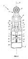
- FIG. 2 is a partly broken away front view of the switch of Fig. 1;
- FIG. 3 is an exploded view of the switch of Fig. 1;
- FIG. 4 is an exploded view of a reset device of the invention;
- FIG. 5 is a sectioned side view of the device of Fig. 4 as taken along the plane I-I, in a first operating configuration;
- FIG. 6 is a sectioned side view of the device of Fig. 4 as taken along the plane I-I, in a second operating configuration;
- FIG. 7 is a sectioned side view of the device of Fig. 4 as taken along the plane I-I, in a third operating configuration;
- FIG. 8 is a sectioned side view of the device of Fig. 4 as taken along the plane I-I, in a fourth operating configuration;
- Fig. 9 is a schematic view, showing the possible combinations of the various parts of a switch of this invention.
- Referring to the above figures, the reset device of the invention, generally designated by numeral 1, may be fitted on a limit switch to be used, for instance, for monitoring any overtravel or abnormal operation in automatic machines and systems, such as elevators and hoists.
- FIG. 1 shows a particular embodiment of a device 1 of the invention, associated to a per se known
limit switch 2. - The
switch 2 is essentially comprised of a lower box-like case 3 for housing one or more pairs of mutually movable contacts, which is associated to acontrol head 4 mounted onto thecase 3 by suitable removable coupling means 5. Thehead 4 at least partly accommodates actuator means 6 for imparting a relative motion to the electric contacts. - These may be inserted in the power circuit of the machine or system served thereby and in an auxiliary service circuit, if any, both not shown, due to their being commonly known and not being part of the present invention.
- In the preferred, non exclusive configuration as particularly shown in FIG. 2, the
case 3 has a double-bridge double-break configuration, having two pairs of fixedelectric contacts movable contacts - The
upper pair 7 is designed to be inserted in the primary power circuit, whereas thelower pair 8 may be connected to the auxiliary signal circuit. - Thus, as the actuator plunger 11 slides in response to the rotation ω of the
handle 12, by means of suitable cam means, not shown, which are held in thehead 4, theupper contacts - At the same time, the pair of lower
movable contacts 10 will be moved to contact with the lower fixedpair 8 to close the secondary circuit, e.g. to generate a visual or sound signal. - One of the purposes of the reset device 1 is to prevent the upper
movable contacts 9 from contacting the upperfixed contacts 7, thereby closing the power circuit, prior to an action by an operator. - According to the invention, the reset device 1, as particularly shown in FIG. 4, has a
modular housing 14 with an upperperipheral edge 16, abottom wall 17 andside walls 15 that define a longitudinal axis X, interface means 18 associated to the housing for removable connection both to thehead 4 and to thecase 3 of thelimit switch 2, reset means 13 at least partly contained in thehousing 14 for controlled turning on and off of thelimit switch 2. - According to a peculiar feature of the invention, the reset means 13 have such a shape as to interact with the actuator means 6 of the
switch 2 to promote positive opening of theelectric contacts switch 2 with which the device 1 is associated is turned on/off. - The term "substantially at the same time" as used herein is intended to mean that the
contacts contacts switch 2 off, and in any case so that one of such actions necessarily entails the other. - In the preferred, non exclusive configuration as shown, the reset means 13 are preferably of the snap-operated type and have a
control rod 34 which moves along a transverse axis Y substantially orthogonal to the axis X. - The
control rod 34 may be held within atubular extension 33 formed on aside wall 15 of thehousing 14 and has anouter end 35 with aknob 36 fitted thereon, which is designed to be grasped by the hand of a user to reset theswitch 2. - Also, the reset means 13 may include a
return rod 37 operably coupled to thecontrol rod 34 and held in thehousing 14 to slide along the longitudinal axis X. - The
control 34 and return 37 rods may be operably coupled together by means of afirst bracket 38 fixed to theinner end 39 of thecontrol rod 34 and asecond bracket 40 attached to theupper end 41 of thereturn rod 37 and opposed to thefirst bracket 38. - The
second bracket 40 may be further configured to interact with theend portion 32 of the actuator means 6 of theswitch 2 with which the device 1 is associated and has an enlargedcentral portion 42 to be acted upon by the plunger actuator 11. - Each of the first 38 and
second brackets 40 may have a pair ofarms corresponding rods - Particularly, the
arms 43 of thefirst bracket 38 have free ends with front contact surfaces 46 designed to abut against side contact surfaces 47 of thearms 44 of thesecond bracket 40 when the device 1 is in the rest condition and theswitch 2 is activated, as more clearly shown in FIG. 5. - The
return rod 37 is preferably external to thehousing 14 so that, in normal operating conditions, it is held within aspecial receptacle 48 formed on thetop surface 28 of thecase 3. - However, its
bracket 40 may have itsarms 44 partly contained in thebody 14 through a pair of diametricallyopposite apertures 50 formed on thebottom wall 17 of thehousing 14. - Also, the
return rod 37 may be equipped with aseal 51 having a shape substantially complementary to itsreceptacle 48, to improve coupling between the device 1 and thecase 3 and prevent any infiltration of dust or other foreign matters into the device 1. - The reset means 13 may further include an
elastic counteracting element 52, such as a helical spring, which will be disposed coaxial with thecontrol rod 34 and will operate on thefirst bracket 38 to urge the front contact surfaces 46 of itsarms 43 against the side contact surfaces 47 of thearms 44 of thesecond bracket 40. - Also, the
arms 43 of thefirst bracket 38 have substantially beveledend corners 53 for interacting with inclined front end surfaces 54 of thearms 44 of thesecond bracket 40 which define ramps for thefirst bracket 38 to slide thereon. - The sliding ramps 54 will be configured to promptly release the
end corners 53 of thearms 43 of thefirst bracket 38, thereby promoting prompt translation of thecontrol rod 34 as the actuator means 6 of theswitch 2 are triggered, thereby allowing the reset device 1 to immediately snap on, and further increasing the safety of the system in which the switch is used. - The interface means 18 may be of standard type, to allow the device 1 to be coupled to any type of
head 4 and/orcase 3 of aswitch 2 with no need of providing special connections for each use. - Thanks to the modular design of the
housing 14, the device 1 will be interchangeable and easily replaceable, while maintaining its reset and positive contact opening functions unchanged. - The interface means 18 have one or more suitably shaped protrusions, 19 and 20 respectively, both on the bottom wall and along the
upper edge 16 of thehousing 14, which are designed for engagement in correspondingrecesses case 3 and thehead 4 respectively of theswitch 2. - In the particular embodiment of the figures, the device 1 will have four substantially
similar protrusions bottom wall 17 and on theupper edge 16, situated peripherally and symmetrically with respect to the axis X. - At the
peripheral edge 23 of thehousing 14, the interface means 18 have substantially longitudinal throughholes 24, each associated to anupper protrusion 20, and having external elongate fastening members extending therethrough, of the screw, pin or similar type, which will also act asremovable means 5 for coupling thecontrol head 4 and thecase 3. - Advantageously, the through
holes 24 will be in such positions as to be in line both with corresponding throughholes 25 formed on theperipheral edge 26 of thehead 4 and withblind holes 27 on thetop surface 28 of thecase 3. - In an alternative embodiment, not shown, the interface means 18 may include, instead of the through
holes 24, one or more dowel pins associated both to theupper edge 16 and to thebottom wall 17 and designed to be fitted in the through 25 andblind holes 27 on thehead 4 and thecase 3. - The generally prismatic shape of the
housing 14, substantially symmetrical with respect to the longitudinal axis X, as well as the symmetrical position of theholes 24, or any other suitably located centering members, will allow orientation of the device 1 and selective coupling thereof in substantially 90° spaced angular positions, as clearly shown in FIG. 3. - In a substantially similar manner, the
head 4 may be in turn rotated to change its position relative both to the device 1 and to thecase 3, still as shown in FIG. 3. - In this figure, the various positions that will be taken by the
extension 33 with thecontrol rod 34 accommodated therein and thehandle 6 are shown by dashed lines. - The
housing 14 may be formed of an upper portion 14' and alower portion 14", which are mutually coupled by male-female connection means 29 associated to their respective contact edges 30', 30". This will facilitate insertion of the reset means 13 in thehousing 14 and assembly of the whole device 1. - To allow the actuator means 6 of the
switch 2 to be coupled with the reset means 13 of the device 1, thehousing 14 will be open at its top, whereas thebottom wall 17 will have an opening 31 substantially at its center, for the passage of anaxial end portion 32 of the plunger actuator 11. - In use, with the system or machine that incorporates the
switch 2 in normal operating conditions, thearms 43 of thecontrol rod 34 has its front contact surfaces 46 urged against their respective side contact surfaces 47 of thebracket 40 of thereturn rod 37, as shown in FIG. 5. - During emergency operation of the
switch 2, the actuator means 6 thereof will interact with the reset means 13 to cause thereturn rod 37 to be longitudinally translated. - As shown in FIG. 6, under the action of the plunger 11, the
return rod 37 will cover a translational travel ta, along the axis X to the point in which theend corners 53 of thearms 43 of thecontrol rod 34 will urge against the corners defined by the side contact surfaces 47 and the beveled surfaces 54. - Therefore, the front contact surfaces 46 will be disengaged from their respective side contact surfaces 47 to allow the
end corners 53 to slip on the corresponding beveled surfaces 54. - Thus, the
contacts return rod 37 with thecontrol rod 34. The action of thespring 52 will urge the latter to translate in the transverse direction, thereby forcing thereturn rod 37 to translate in the contact opening direction. - The
arms 43 of thefirst bracket 38 will slip on the ramps defined by thebeveled surfaces 54 to abutment against respectiveinner protrusions 56 suitably disposed in thehousing 14, to allow thereturn rod 37 to complete its travel ta", as shown in FIG. 8. - This operating condition of the reset means 13 will correspond, in the configuration of the
switch 2 as shown in the present figures, to an open condition of the main circuit and to a closed condition of the secondary circuit. - The
switch 2 may be reset by manually pulling thecontrol rod 34, i.e. theknob 36 to move the contact surfaces 46 of thearms 43 of thefirst bracket 38 back to abutment against the side contact surfaces 47 of thearms 44 of thesecond bracket 40. - The action of the
return spring 57 on the bridge of themovable contacts 9 will allow the latter to move back onto their respective fixedcontacts 7 to close the power circuit. - Other solutions may be provided in which, for example, the
switch 2 is reset by pushing theknob 36. Nevertheless, the operating conditions as shown in the annexed figures provide higher safety as they prevent any accidental triggering of the reset device 1. - The above disclosure clearly shows that the invention fulfills the intended objects and particularly meets the requirement of providing a reset device that ensures high operation safety and can be fitted on a commonly
available limit switch 2 in a modular and interchangeable manner, while maintaining its functions unchanged. - Thanks to the particular configuration of the interface means 18 and to their compliance with the commonly used limit switch standards, different types of control heads 4 or different actuator means 6 may be associated to each
case 3 of thecontacts switch 2, with no need to make changes to the various parts or adapt the reset device 1. Likewise, different types ofcases 3 may be associated to eachhead 4, as shown in FIG. 9. - The reset device and limit switch of this invention are susceptible of a number of changes or variants, within the inventive concept disclosed in the appended claims. All the details thereof may be replaced by other technically equivalent parts, and the materials may vary depending on different needs, without departure from the scope of the invention.
- While the reset device and switch have been described with particular reference to the accompanying figures, the numerals referred to in the disclosure and claims are only used for the sake of a better intelligibility of the invention and shall not be intended to limit the claimed scope in any manner.
Claims (17)
- A reset device to be coupled to a limit switch (2) having a case (3) designed to contain at least one pair of electric contacts (7, 9) and a control head (4) having internally thereof actuator means (6) for mutually moving the contacts (7, 9), wherein the device comprises:- a modular housing (14) with an upper peripheral edge (16), a bottom wall (17) and side walls (15) defining a longitudinal axis (X);- interface means (18) associated to said housing for removable connection both to the head (4) and to the case (3) of the limit switch (2) with which the device is coupled;- reset means (13) at least partly contained in said housing (14) for controlled activation/deactivation of the limit switch (2) with which it is coupled;characterized in that said reset means are so shaped as to interact with the actuator means of the switch to promote positive opening of the electric contacts substantially at the same time as the switch with which the device is activated/deactivated.
- Reset device as claimed in claim 1, characterized in that said reset means (13) comprise a control rod (34) at least partly movable in said housing (14) along a transverse axis (Y) substantially perpendicular to said longitudinal axis (X).
- Reset device as claimed in claim 2, characterized in that said reset means (13) further comprise a return rod (37) operably coupled to said control rod (34) and at least partly contained in said housing (14) for sliding along said longitudinal axis (X).
- Reset device as claimed in claim 3, characterized in that said control rod (34) and said return rod (37) are operably coupled together by a first bracket (38) fixed to the inner end (39) of said control rod (34) and opposite to a second bracket (40) attached to the upper end (41) of said return rod (37), said second bracket (40) being configured to interact with the end portion (32) of the actuator means (6) of the switch (2) with which the device is associated.
- Reset device as claimed in claim 4, characterized in that said first (38) and said second brackets (40) have each a pair of arms (43, 44), which are substantially identical and symmetrical with respect to their corresponding rods (34, 37), the arms (43) of said first bracket (38) having free ends with front contact surfaces (46) designed to abut against respective side contact surfaces (47) of the arms (44) of said second bracket (40) when the device is in the rest condition and the switch (2) is turned on.
- Reset device as claimed in claim 5, characterized in that said reset means (13) further include an elastic counteracting element (52) operating on said first bracket (38) to urge the front contact surfaces (46) of its respective arms (43) against the side contact surfaces (47) of the arms (44) of said second bracket (40).
- Reset device as claimed in claim 5, characterized in that the arms (43) of said first bracket (38) have end corners (53) which are designed to interact with inclined front end surfaces (54) of the arms (44) of said second bracket (40) which define sliding ramps for said first bracket (38).
- Reset device as claimed in claim 7, characterized in that said sliding ramps (54) are configured to promptly release the respective end corners (53), thereby promoting prompt translation (ta") of said control rod (34) as the actuator means (6) of the switch (2) with which the device is associated are triggered, and interaction thereof with said second bracket (40).
- Reset device as claimed in any preceding claim, characterized in that said control rod (34) has an outer end (35) with a knob (36) fitted thereon, which is designed to be grasped by the hand of a user to reset the switch (2).
- Reset device as claimed in claim 1, characterized in that said interface means (18) have one or more suitably shaped protrusions (19, 20) both on said bottom wall (17) and along said upper peripheral edge (16) of said housing (14), which are designed for engagement in corresponding recesses (21, 22) of complementary shape on the case (3) and the head (4) respectively of the switch (2) with which the device is associated.
- Reset device as claimed in claim 1, characterized in that said interface means (18) have at least one substantially longitudinal through hole (24) at the peripheral edge (23) of said housing (14), which is adapted to be passed through external by elongate fastening members (5) of the screw, pin or similar type.
- Reset device as claimed in claim 1, characterized in that said housing (14) has a generally prismatic shape, substantially symmetric with respect to said longitudinal axis (X) to allow orientation and selective coupling thereof in substantially 90° spaced angular positions.
- Reset device as claimed in any preceding claim, characterized in that said housing (14) has a tubular extension (33), transversely extending from one of said side walls (15) for at least partly slideably accommodating said control rod (34).
- Reset device as claimed in any preceding claim, characterized in that said housing (14) is open at its top, said bottom wall (17) having an opening (31) for the passage of an end portion (32) of the actuator means (6) of the switch with which the device is associated, for interaction with said reset means (13).
- Reset device as claimed in any preceding claim, characterized in that said bottom wall (17) of said housing (14) has a pair of diametrically opposite openings (50) allowing the passage of the ends of the arms (44) of said second bracket (40).
- A limit switch comprising:- a box-like case (3) which houses at least one pair of mutually movable electric contacts (7, 9) designed to be inserted in an external electric circuit of a machine or a system;- actuator means (6) operating on at least one of said contacts (9) for causing the circuit to open/close;- a control head (4) for at least partly accommodating said actuator means (6);- means (5) for removably coupling said control head (4) to said box-like case (3);characterized in that it comprises a reset device as claimed in any one of claims 1 to 15 and interposed between said head (4) and said case (3).
- A kit comprising at least one box-like case (3) which houses at least one pair of mutually movable electric contacts (7, 9), one or more control heads (4) designed to at least partly accommodate respective actuator means (6) operating on at least one of said contacts (9) to promote mutual motion of said contacts (7, 9), one or more reset devices (1) as claimed in any one of claims 1 to 14, designed to be simultaneously associated to one of said cases (3) and one of said control heads (4) at a time.
Applications Claiming Priority (1)
| Application Number | Priority Date | Filing Date | Title |
|---|---|---|---|
| ITVI20060211 ITVI20060211A1 (en) | 2006-07-07 | 2006-07-07 | RESET DEVICE FOR LIMIT SWITCH AND LIMIT SWITCH INCLUDING THIS DEVICE |
Publications (3)
| Publication Number | Publication Date |
|---|---|
| EP1876616A2 true EP1876616A2 (en) | 2008-01-09 |
| EP1876616A3 EP1876616A3 (en) | 2009-02-25 |
| EP1876616B1 EP1876616B1 (en) | 2011-09-14 |
Family
ID=38521207
Family Applications (1)
| Application Number | Title | Priority Date | Filing Date |
|---|---|---|---|
| EP20070012965 Active EP1876616B1 (en) | 2006-07-07 | 2007-07-03 | Reset device for limit switch and limit switch incorporating such device |
Country Status (2)
| Country | Link |
|---|---|
| EP (1) | EP1876616B1 (en) |
| IT (1) | ITVI20060211A1 (en) |
Cited By (8)
| Publication number | Priority date | Publication date | Assignee | Title |
|---|---|---|---|---|
| WO2014117248A1 (en) * | 2013-01-31 | 2014-08-07 | Messier-Dowty Inc. | Switch assembly and over-steer detection system |
| FR3010826A1 (en) * | 2013-09-19 | 2015-03-20 | Schneider Electric Ind Sas | POSITION SWITCH |
| CN105531786A (en) * | 2013-12-06 | 2016-04-27 | 彼扎特电气有限公司 | Time-delay manually operated safety switch |
| WO2016135141A1 (en) * | 2015-02-23 | 2016-09-01 | steute Schaltgeräte GmbH & Co. KG | Position switch actuator |
| WO2017024545A1 (en) * | 2015-08-12 | 2017-02-16 | Honeywell International Inc. | Limit switch with integrated reset key |
| US9928972B1 (en) | 2016-11-09 | 2018-03-27 | Honeywell International Inc. | Limit switch housing with reset function |
| US10303247B2 (en) | 2015-01-16 | 2019-05-28 | Hewlett-Packard Development Company, L.P. | User gaze detection |
| DE102022134490A1 (en) | 2022-12-22 | 2024-06-27 | Marelli Automotive Lighting Reutlingen (Germany) GmbH | Deformation sensor designed to detect a deformation of an external component of a motor vehicle |
Citations (1)
| Publication number | Priority date | Publication date | Assignee | Title |
|---|---|---|---|---|
| JPH08111141A (en) | 1994-10-13 | 1996-04-30 | Omron Corp | switch |
Family Cites Families (3)
| Publication number | Priority date | Publication date | Assignee | Title |
|---|---|---|---|---|
| DE3043240A1 (en) * | 1980-11-15 | 1982-09-30 | Klöckner-Moeller Elektrizitäts GmbH, 5300 Bonn | LV push-pull switch for hand or foot usage - has spring assisted operation and magnet or catch release for pull and hold position |
| IT1274662B (en) * | 1994-04-12 | 1997-07-24 | Reiter Srl | MULTI-FUNCTIONAL LIMIT SWITCH |
| FR2830981B1 (en) * | 2001-10-15 | 2004-10-15 | Schneider Electric Ind Sa | SWITCH, ESPECIALLY POSITIONING, WITH ADJUSTABLE HEAD |
-
2006
- 2006-07-07 IT ITVI20060211 patent/ITVI20060211A1/en unknown
-
2007
- 2007-07-03 EP EP20070012965 patent/EP1876616B1/en active Active
Patent Citations (1)
| Publication number | Priority date | Publication date | Assignee | Title |
|---|---|---|---|---|
| JPH08111141A (en) | 1994-10-13 | 1996-04-30 | Omron Corp | switch |
Cited By (15)
| Publication number | Priority date | Publication date | Assignee | Title |
|---|---|---|---|---|
| WO2014117248A1 (en) * | 2013-01-31 | 2014-08-07 | Messier-Dowty Inc. | Switch assembly and over-steer detection system |
| CN105102328A (en) * | 2013-01-31 | 2015-11-25 | 梅西埃-道蒂公司 | Switch assembly and over-steer detection system |
| FR3010826A1 (en) * | 2013-09-19 | 2015-03-20 | Schneider Electric Ind Sas | POSITION SWITCH |
| EP2851917A1 (en) | 2013-09-19 | 2015-03-25 | Schneider Electric Industries SAS | Limit switch |
| CN104465191A (en) * | 2013-09-19 | 2015-03-25 | 施耐德电器工业公司 | Limit switch |
| US9281143B2 (en) | 2013-09-19 | 2016-03-08 | Schneider Electric Industries Sas | Limit switch |
| CN105531786A (en) * | 2013-12-06 | 2016-04-27 | 彼扎特电气有限公司 | Time-delay manually operated safety switch |
| CN105531786B (en) * | 2013-12-06 | 2018-12-18 | 彼扎特电气有限公司 | Time-delay manually operated safety switch |
| US10303247B2 (en) | 2015-01-16 | 2019-05-28 | Hewlett-Packard Development Company, L.P. | User gaze detection |
| WO2016135141A1 (en) * | 2015-02-23 | 2016-09-01 | steute Schaltgeräte GmbH & Co. KG | Position switch actuator |
| WO2017024545A1 (en) * | 2015-08-12 | 2017-02-16 | Honeywell International Inc. | Limit switch with integrated reset key |
| CN108292569A (en) * | 2015-08-12 | 2018-07-17 | 霍尼韦尔国际公司 | Limit switch with integral type reset key |
| CN108292569B (en) * | 2015-08-12 | 2020-04-10 | 霍尼韦尔国际公司 | Limit switch with integrated reset key |
| US9928972B1 (en) | 2016-11-09 | 2018-03-27 | Honeywell International Inc. | Limit switch housing with reset function |
| DE102022134490A1 (en) | 2022-12-22 | 2024-06-27 | Marelli Automotive Lighting Reutlingen (Germany) GmbH | Deformation sensor designed to detect a deformation of an external component of a motor vehicle |
Also Published As
| Publication number | Publication date |
|---|---|
| EP1876616A3 (en) | 2009-02-25 |
| ITVI20060211A1 (en) | 2008-01-08 |
| EP1876616B1 (en) | 2011-09-14 |
Similar Documents
| Publication | Publication Date | Title |
|---|---|---|
| EP1876616B1 (en) | Reset device for limit switch and limit switch incorporating such device | |
| US9653235B2 (en) | Switch device | |
| KR20180104103A (en) | Operating mechanism of rotary switch | |
| KR101195285B1 (en) | Switching device | |
| EP2492944B1 (en) | Circuit breaker | |
| EP3273462B1 (en) | Toggle switch actuating mechanism | |
| EP3343710B1 (en) | Position indicator of air circuit breaker | |
| EP3903335B1 (en) | Interlock system for a circuit breaker system | |
| JP6996924B2 (en) | switch | |
| KR100794459B1 (en) | Mechanical reset device for switch | |
| CN102412079B (en) | Push button with mechanical signal display | |
| CN105841107B (en) | End cap of lighting device and lighting device comprising same | |
| EP1548784B1 (en) | Interlocking apparatus of a leading under voltage trip mechanism for manual motor starter | |
| CN105225865A (en) | A high-voltage cabinet safety device | |
| JPH08159388A (en) | Safety switch | |
| CN111161963B (en) | Switch assembly with safety accessory solution for emergency stop device | |
| US10354822B2 (en) | Electrical switch, in particular a switch for an electrical power tool | |
| EP2141715B1 (en) | Safety switch | |
| US10199181B2 (en) | Holding device for receiving switching elements for a command and alert device | |
| CN121394744B (en) | Reciprocating cutting tool | |
| JPH08167350A (en) | Switch device | |
| KR101601910B1 (en) | Switching Device for Contact Breaker providing safety function of On Mode change | |
| JP2008226604A (en) | Push-button switch | |
| EP1772880B1 (en) | Safety switch | |
| US20180267568A1 (en) | Rotary actuator |
Legal Events
| Date | Code | Title | Description |
|---|---|---|---|
| PUAI | Public reference made under article 153(3) epc to a published international application that has entered the european phase |
Free format text: ORIGINAL CODE: 0009012 |
|
| AK | Designated contracting states |
Kind code of ref document: A2 Designated state(s): AT BE BG CH CY CZ DE DK EE ES FI FR GB GR HU IE IS IT LI LT LU LV MC MT NL PL PT RO SE SI SK TR |
|
| AX | Request for extension of the european patent |
Extension state: AL BA HR MK YU |
|
| PUAL | Search report despatched |
Free format text: ORIGINAL CODE: 0009013 |
|
| AK | Designated contracting states |
Kind code of ref document: A3 Designated state(s): AT BE BG CH CY CZ DE DK EE ES FI FR GB GR HU IE IS IT LI LT LU LV MC MT NL PL PT RO SE SI SK TR |
|
| AX | Request for extension of the european patent |
Extension state: AL BA HR MK RS |
|
| RIC1 | Information provided on ipc code assigned before grant |
Ipc: H01H 21/28 20060101ALI20090121BHEP Ipc: H01H 11/00 20060101AFI20090121BHEP Ipc: H01H 3/20 20060101ALN20090121BHEP Ipc: H01H 13/68 20060101ALI20090121BHEP |
|
| 17P | Request for examination filed |
Effective date: 20090629 |
|
| 17Q | First examination report despatched |
Effective date: 20090909 |
|
| AKX | Designation fees paid |
Designated state(s): DE FR GB IT |
|
| GRAP | Despatch of communication of intention to grant a patent |
Free format text: ORIGINAL CODE: EPIDOSNIGR1 |
|
| GRAS | Grant fee paid |
Free format text: ORIGINAL CODE: EPIDOSNIGR3 |
|
| GRAA | (expected) grant |
Free format text: ORIGINAL CODE: 0009210 |
|
| AK | Designated contracting states |
Kind code of ref document: B1 Designated state(s): DE FR GB IT |
|
| REG | Reference to a national code |
Ref country code: GB Ref legal event code: FG4D |
|
| REG | Reference to a national code |
Ref country code: DE Ref legal event code: R096 Ref document number: 602007017106 Country of ref document: DE Effective date: 20111110 |
|
| PLBE | No opposition filed within time limit |
Free format text: ORIGINAL CODE: 0009261 |
|
| STAA | Information on the status of an ep patent application or granted ep patent |
Free format text: STATUS: NO OPPOSITION FILED WITHIN TIME LIMIT |
|
| 26N | No opposition filed |
Effective date: 20120615 |
|
| REG | Reference to a national code |
Ref country code: DE Ref legal event code: R097 Ref document number: 602007017106 Country of ref document: DE Effective date: 20120615 |
|
| REG | Reference to a national code |
Ref country code: FR Ref legal event code: PLFP Year of fee payment: 10 |
|
| REG | Reference to a national code |
Ref country code: FR Ref legal event code: PLFP Year of fee payment: 11 |
|
| REG | Reference to a national code |
Ref country code: FR Ref legal event code: PLFP Year of fee payment: 12 |
|
| P01 | Opt-out of the competence of the unified patent court (upc) registered |
Effective date: 20230526 |
|
| PGFP | Annual fee paid to national office [announced via postgrant information from national office to epo] |
Ref country code: DE Payment date: 20250729 Year of fee payment: 19 |
|
| PGFP | Annual fee paid to national office [announced via postgrant information from national office to epo] |
Ref country code: IT Payment date: 20250721 Year of fee payment: 19 |
|
| PGFP | Annual fee paid to national office [announced via postgrant information from national office to epo] |
Ref country code: GB Payment date: 20250728 Year of fee payment: 19 |
|
| PGFP | Annual fee paid to national office [announced via postgrant information from national office to epo] |
Ref country code: FR Payment date: 20250725 Year of fee payment: 19 |