EP1879793B1 - Einrichtung zur bearbeitung eines tankbehälters - Google Patents
Einrichtung zur bearbeitung eines tankbehälters Download PDFInfo
- Publication number
- EP1879793B1 EP1879793B1 EP06721243A EP06721243A EP1879793B1 EP 1879793 B1 EP1879793 B1 EP 1879793B1 EP 06721243 A EP06721243 A EP 06721243A EP 06721243 A EP06721243 A EP 06721243A EP 1879793 B1 EP1879793 B1 EP 1879793B1
- Authority
- EP
- European Patent Office
- Prior art keywords
- tube
- mast
- booms
- platforms
- carrier portion
- Prior art date
- Legal status (The legal status is an assumption and is not a legal conclusion. Google has not performed a legal analysis and makes no representation as to the accuracy of the status listed.)
- Expired - Lifetime
Links
Images

Classifications
-
- B—PERFORMING OPERATIONS; TRANSPORTING
- B63—SHIPS OR OTHER WATERBORNE VESSELS; RELATED EQUIPMENT
- B63B—SHIPS OR OTHER WATERBORNE VESSELS; EQUIPMENT FOR SHIPPING
- B63B81/00—Repairing or maintaining vessels
-
- B—PERFORMING OPERATIONS; TRANSPORTING
- B63—SHIPS OR OTHER WATERBORNE VESSELS; RELATED EQUIPMENT
- B63B—SHIPS OR OTHER WATERBORNE VESSELS; EQUIPMENT FOR SHIPPING
- B63B71/00—Designing vessels; Predicting their performance
Definitions
- the invention relates to a device for approaching working platforms to the inner walls of a tank space, wherein for pivoting the platforms boom are provided, which are held by an insertable through an upper opening of the tank space mast.
- a conventional tanker is divided into tank rooms with dimensions of 20 mx 20 mx 20 m. These have a standardized upper filler opening of 1250 x 750 mm, which represents the only access to the tank room apart from a manhole for operators.
- movable working stations are provided in three directions, from which the inner walls can be inspected, treated with sandblasting, phosphorized and painted. Even to minimize the downtime of the ship in the yard, but also for technical reasons, the processing of the entire interior should be completed in the shortest possible time. In this sense, it is advisable to arrange more than one work basket on the central mast, with the use of four baskets in practice is probably the upper limit.
- the device is already largely ready for use, as soon as the boom is pushed through the pipe down. It is only necessary to connect the working baskets, which have been introduced in advance into the tank space, and at most these articulated arms, which connect with the arms, to the outriggers.
- a particular advantage of the invention is that the formation of the mast as a tube, the available clear width of the upper opening of the tank space static maximum utilization and at the same time provides a space for the arrangement of supply lines.
- the bottom of the tank room may only be moderately loaded, it can absorb horizontal forces. This is advantageously utilized by a further mast is connected to the support member, for which at the bottom of the tank space a backup against horizontal displacement is provided.
- this supported on the ground further mast is also designed as a tube. This makes it possible to accommodate supply lines in the initial state in a collapsed form in this tube. These supply lines then extend after the extension of the boom from the support member of the boom to the recess provided in the deck.
- the basic idea of the invention is to stow the arms of a processing device in a folded state in a tube 1.
- This cladding initially serves as protection against damage to the difficult mechanics and designed to the strength limit steel structure in rough shipyard operation. It allows horizontal storage of the system on the ship until the tube 1 is brought with the stowed boom from the ship's crane 15 by means of a steel cable 7 to the site.
- the tube 1 together with the cantilevers mounted therein is lowered by the opening of a tank space formed by a dome 13 and connected to the dome 13 after complete lowering by means of an automatic lock 16.
- Tube 1 Since that Tube 1 is now fixed to the dome 13, go on further lowering of the rope 7 attached to a support member 3 boom 2 down (second and third pictures in Fig. 1 ). Subsequently, the still to be described in detail locking of the support member 3 at the lower end of the tube 1 and finally the connection of the boom 2 with prepared articulated arms 5 and 6 platforms.
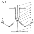
- a lateral deflection of the whole device under the load exerted by the platforms is in the embodiment after Fig. 2 prevented by a fuse 10, in which a likewise formed as a tube further mast 4 engages. This is based on the bottom 12 predominantly from the side, so that the weight of the assembly does not have to be absorbed by the bottom 12, but is collected by the deck 11 supporting struts.
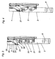
- extension arms 2 are sufficiently spaced so that the free ends of the extension arms 2 can be pivoted about the vertical axes 8 relative to their ends formed by the vertical struts 22.
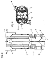
- FIG. 5 is a side view of the lowered by the tube 1 middle part 3. It is clearly seen that in this Fig. 4 corresponding position, the pivot drives 17 for the boom 2 can move them without mutual interference.
- Fig. 6 is additionally illustrated by the example of two arms 2, as the pivoting of the boom about horizontal axes 9 can take place. But above all, you can see how the other two are in position Fig. 3 boom shown fit into the tube 1 and how exactly the other hand, the tube 1 rests against the inside of the mandrel 13. Above the support member 3 is in the pipe 1 sufficient space for supply lines. These can be arranged during the retraction and extension of the support member 3 in the support member downwardly continuing pipe 4, which is fixedly connected to the support member 3. Incidentally, this tube 4 serves to firmly anchor the entire device to the bottom 12 of the tank space.
Landscapes
- Chemical & Material Sciences (AREA)
- Engineering & Computer Science (AREA)
- Combustion & Propulsion (AREA)
- Mechanical Engineering (AREA)
- Ocean & Marine Engineering (AREA)
- Jib Cranes (AREA)
- Cleaning In General (AREA)
- Working Measures On Existing Buildindgs (AREA)
- Electrical Discharge Machining, Electrochemical Machining, And Combined Machining (AREA)
- Finish Polishing, Edge Sharpening, And Grinding By Specific Grinding Devices (AREA)
Description
- Die Erfindung bezieht sich auf eine Einrichtung zum Heranführen von Arbeitsplattformen an die Innenwände eines Tankraumes, wobei zur Verschwenkung der Plattformen Ausleger vorgesehen sind, welche von einem durch eine obere Öffnung des Tankraumes einführbaren Mast gehalten werden.
- Ein üblicher Tanker ist in Tankräume mit Abmessungen von 20 m x 20 m x 20 m unterteilt. Diese weisen eine standarisierte obere Einfüllöffnung von 1250 x 750 mm auf, welche abgesehen von einer Einstiegsöffnung für Bedienungspersonal den einzigen Zugang zum Tankraum darstellt. Zur Bearbeitung der Innenwände des Tankraumes sind in drei Richtungen verfahrbare Arbeitsstationen vorgesehen, von denen aus die Innenwände inspiziert, mit Sandstrahlen behandelt, phosphorisiert und lackiert werden können. Schon um die Stillstandszeiten des Schiffes in der Werft zu minimieren, aber auch aus technischen Gründen soll die Bearbeitung des gesamten Innenraumes in möglichst kurzer Zeit abgeschlossen sein. In diesem Sinne empfiehlt es sich, mehr als einen Arbeitskorb am zentralen Mast anzuordnen, wobei der Einsatz von vier Körben in der Praxis wohl obere Grenze darstellt.
- Bei einer bekannten Einrichtung der eingangs erwähnten Art (vergl.
DE 24 50 604 A1 ) ist keine Möglichkeit vorgesehen, einen weitgehenden Zusammenbau bereits außerhalb des Tankraumes vorzunehmen. Ein Zusammenbau im Inneren des Tankraumes ist aber wegen der dort herrschenden Arbeitsbedingungen schwierig. Die diesbezüglichen Tätigkeiten sollen daher auf ein Minimum reduziert werden. Erfindungsgemäß ist zur Lösung dieser Aufgabe vorgesehen, dass zumindest der obere Teil des Mastes als Rohr ausgebildet ist, und dass die Ausleger zusammen mit einem Tragteil, an dem sie angelenkt sind, durch das Rohr bewegbar sind. Der Stand der Technik DokumentWO 93/07082 - Durch die Erfindung ist die Einrichtung bereits weitgehend gebrauchsfertig, sobald die Ausleger durch das Rohr nach unten ausgeschoben sind. Es ist lediglich noch notwendig, die vorweg in den Tankraum eingeführten Arbeitskörbe und allenfalls diese mit den Auslegern verbindenden Knickarme an die Ausleger anzuschließen.
- Ein besonderer Vorteil der Erfindung besteht darin, dass die Ausbildung des Mastes als Rohr die zur Verfügung stehende lichte Weite der oberen Öffnung des Tankraumes statisch maximal ausnützt und gleichzeitig einen Raum für die Anordnung von Versorgungsleitungen zur Verfügung stellt.
- Der Boden des Tankraumes darf zwar nur mäßig belastet werden, er kann jedoch horizontale Kräfte aufnehmen. Dies wird vorteilhafterweise ausgenützt, indem mit dem Tragteil ein weiterer Mast verbunden ist, für den am Boden des Tankraumes eine Sicherung gegen horizontales Verschieben vorgesehen ist.
- Günstig ist es, wenn dieser am Boden abgestützte weitere Mast ebenfalls als Rohr ausgebildet ist. Dies ermöglicht es, Versorgungsleitungen im Ausgangszustand in zusammengelegter Form in diesem Rohr unterzubringen. Diese Versorgungsleitungen erstrecken sich dann nach dem Ausfahren der Ausleger vom Tragteil der Ausleger zu der im Deck vorgesehenen Ausnehmung.
- Weitere Einzelheiten der Erfindung werden anschließend anhand der Zeichnung erläutert. In dieser zeigt
- Fig. 1
- schematisch die verschiedenen Phasen des Einbringens und des Aufbaues einer erfindungsgemäßen Einrichtung in einem Tankraum,
- Fig. 2
- die schematische Darstellung eines zweiten Ausführungsbeispiels (mit unterer Abstützung)
- Fig. 3
- im Schnitt die Anordnung eines Auslegers unmittelbar nach dem Ausfahren,
- Fig. 4
- die Einrichtung nach
Fig. 3 nach dem radialen Ausschwenken des Auslegers, - Fig. 5
- eine Seitenansicht entsprechend
Fig. 3 und - Fig. 6
- einen Schnitt zur
Fig. 5 nach der Linie A-A. - Der Grundgedanke der Erfindung besteht darin, die Ausleger einer Bearbeitungseinrichtung in zusammengefaltetem Zustand in einem Rohr 1 zu verstauen. Dieses Hüllrohr dient zunächst als Schutz gegen Beschädigung der diffizilen Mechanik und der an die Festigkeitsgrenze ausgelegten Stahlbaustruktur im rauen Werftbetrieb. Sie erlaubt eine horizontale Lagerung des Systems auf dem Schiff bis das Rohr 1 mit den darin verstauten Auslegern vom Schiffskran 15 mittels eines Stahlseiles 7 an die Einsatzstelle gebracht wird. Dort wird (linkes Bild in
Fig. 1 ) das Rohr 1 samt den darin gelagerten Auslegern durch die von einem Dom 13 gebildeten Öffnung eines Tankraums abgesenkt und nach vollständiger Absenkung mittels einer automatischen Verriegelung 16 mit dem Dom 13 verbunden. Da das Rohr 1 nunmehr am Dom 13 festliegt, fahren bei weiterem Absenken des Seiles 7 an einem Tragteil 3 befestigte Ausleger 2 nach unten aus (zweites und drittes Bilde inFig. 1 ). Anschließend erfolgt die im Detail noch zu beschreibende Verriegelung des Tragteiles 3 am unteren Ende des Rohres 1 und schließlich die Verbindung der Ausleger 2 mit vorbereiteten Knickarmen 5 und Plattformen 6. - Ein seitliches Auslenken der ganzen Einrichtung unter der von den Plattformen ausgeübten Belastung wird beim Ausführungsbeispiel nach
Fig. 2 durch eine Sicherung 10 verhindert, in welche ein ebenfalls als Rohr ausgebildeter weiterer Mast 4 eingreift. Dieser stützt sich am Boden 12 vorwiegend zur Seite hin ab, damit das Gewicht der Anordnung nicht vom Boden 12 aufgenommen werden muss, sondern von den das Deck 11 tragenden Streben aufgefangen wird. - Im eingefahrenen Zustand müssen die Ausleger 2 sehr eng aneinander liegen, damit sie im Rohr 1 verpackt werden können. Eine Drehung der Ausleger wäre in dieser Konfiguration kaum möglich, weshalb nach dem Ausfahren der Ausleger 2 aus dem Rohr 1 die Ausleger 2 aus der Stellung gemäß
Fig. 3 in die Stellung nachFig. 4 parallel verschoben werden. Diese radiale Verschiebung um etwa 100 mm kann über einen Viergelenksmechanismus erfolgen, welcher einen oberen Lenker 20 und einen unteren Lenker 21 umfasst, welche am Tragteil 3 der Einrichtung befestigt sind. An dem oberen Lenker 20 ist ein Kniehebel 28 drehbar gelagert, welcher mit dem Verriegelungszylinder 26 gelenkig verbunden ist. - Bei Ausfahren des Mittelteiles 3 mit den daran befestigten Auslegern 2 durch das Rohr 1 nach unten, kommt zunächst der Anschlagflügel 23 am Flansch 31 des Rohres 1 zum Anschlag. Dieser Anschlagflügel 23 ist in zwei Richtungen über Schrauben 24, 25 verstellbar.
- Bei weiterer Zugabe von Seil vom Schiffskran her erschlafft das Seil, wodurch das Ausfahren des Zylinders 26 möglich wird. Durch das Eigengewicht des aus den Auslegern 2 und den Lenkern 20, 21 bestehenden Armsystems bewegt sich dieses so weit nach außen, bis der an der Verlängerung des oberen Lenkers 20 befindliche Anschlag 27 auf eine definierte Fläche am Hüllrohr 1 bzw. am Anschlagflügel 23 trifft. Trifft der Anschlag 27 zuerst auf das Hüllrohr 1, bewirkt dies eine Zentrierung desselben gegenüber dem Tragteil 3. Ein Kunststoffblock 29 verhindert dabei ein zu großes Auslenken des Verriegelungszylinders 26.
- In der Position nach
Fig. 4 weisen die Ausleger 2 hinreichenden Abstand voneinander auf, sodass die freien Enden der Ausleger 2 relativ zu ihren durch die Vertikalstreben 22 gebildeten Enden um die vertikalen Achsen 8 verschwenkt werden können. - Eine Möglichkeit zur Durchführung der erwähnten Schwenkbewegung ist in
Fig. 5 und Fig. 6 dargestellt.Fig. 5 ist dabei eine Seitenansicht des durch das Rohr 1 herabgelassenen Mittelteils 3. Es ist deutlich erkennbar, dass in dieserFig. 4 entsprechenden Position die Schwenkantriebe 17 für die Ausleger 2 diese ohne gegenseitige Behinderung bewegen können. - In
Fig. 6 ist zusätzlich am Beispiel von zwei Auslegern 2 dargestellt, wie die Verschwenkung der Ausleger um horizontale Achsen 9 erfolgen kann. Vor allem aber sieht man, wie die beiden anderen in der Position nachFig. 3 dargestellten Ausleger in das Rohr 1 passen und wie genau andererseits das Rohr 1 an der Innenseite des Doms 13 anliegt. Oberhalb des Tragteils 3 besteht im Rohr 1 ausreichend Platz für Zuführleitungen. Diese können während des Ein- und Ausfahrens des Tragteils 3 in dem den Tragteil nach unten fortsetzenden Rohr 4 angeordnet sein, welches mit dem Tragteil 3 fest verbunden ist. Dieses Rohr 4 dient im Übrigen dazu, die gesamte Einrichtung am Boden 12 des Tankraumes fest zu verankern.
Claims (9)
- Einrichtung zum Heranführen von Arbeitsplattformen an die Innenwände eines Tankraumes, wobei zur Verschwenkung der Plattformen Ausleger vorgesehen sind, welche von einem durch eine obere Öffnung des Tankraumes einführbaren Mast gehalten werden, wobei zumindest der obere Teil des Mastes als Rohr (1) ausgebildet ist, und dass die Ausleger (2) zusammen mit einem Tragteil (3), an dem sie angelenkt sind, durch das Rohr (1) bewegbar sind.
- Einrichtung nach Anspruch 1, dadurch gekennzeichnet, dass die Ausleger (2) um eine vertikale Achse (8) und eine horizontale Achse (9) schwenkbar sind.
- Einrichtung nach Anspruch 1, dadurch gekennzeichnet, dass die vertikalen Schwenkachsen (8) der Ausleger (2) radial zum Rohr (1) verschiebbar sind.
- Einrichtung nach Anspruch 2 oder 3, dadurch gekennzeichnet, dass die Ausleger (2) mittels Knickarmen (5) mit den Plattformen (6) verbunden sind.
- Einrichtung nach einem der Ansprüche 1 bis 4, dadurch gekennzeichnet, dass mit dem Tragteil (3) ein weiterer Mast (4) verbunden ist, für den am Boden (12) des Tankraumes eine Sicherung (10) gegen horizontales Verschieben vorgesehen ist.
- Einrichtung nach Anspruch 5, dadurch gekennzeichnet, dass der weitere Mast (4) als hohler ausgebildet ist, in welchem Versorgungsleitungen (14) angeordnet sind.
- Einrichtung nach Anspruch 6, dadurch gekennzeichnet, dass der Mast (4) einen sternförmigen Querschnitt aufweist.
- Einrichtung nach einem der Ansprüche 1 bis 7, dadurch gekennzeichnet, dass das Tragteil (3) vorzugsweise am unteren Ende des Rohres (1) verriegelbar ist.
- Einrichtung nach Anspruch 8, dadurch gekennzeichnet, dass das Tragteil (3) in ausgefahrenem Zustand an einem Flansch (31) am unteren Ende des Rohres (1) anschlägt.
Applications Claiming Priority (2)
| Application Number | Priority Date | Filing Date | Title |
|---|---|---|---|
| AT0082705A AT501747B1 (de) | 2005-05-13 | 2005-05-13 | Einrichtung zur bearbeitung eines tankbehälters |
| PCT/AT2006/000186 WO2006119520A1 (de) | 2005-05-13 | 2006-05-05 | Einrichtung zur bearbeitung eines tankbehälters |
Publications (2)
| Publication Number | Publication Date |
|---|---|
| EP1879793A1 EP1879793A1 (de) | 2008-01-23 |
| EP1879793B1 true EP1879793B1 (de) | 2010-08-11 |
Family
ID=36691892
Family Applications (1)
| Application Number | Title | Priority Date | Filing Date |
|---|---|---|---|
| EP06721243A Expired - Lifetime EP1879793B1 (de) | 2005-05-13 | 2006-05-05 | Einrichtung zur bearbeitung eines tankbehälters |
Country Status (4)
| Country | Link |
|---|---|
| EP (1) | EP1879793B1 (de) |
| AT (2) | AT501747B1 (de) |
| DE (1) | DE502006007643D1 (de) |
| WO (1) | WO2006119520A1 (de) |
Cited By (1)
| Publication number | Priority date | Publication date | Assignee | Title |
|---|---|---|---|---|
| AT512891A4 (de) * | 2012-07-30 | 2013-12-15 | Palfinger Systems Gmbh | Instandhaltungsvorrichtung |
Families Citing this family (1)
| Publication number | Priority date | Publication date | Assignee | Title |
|---|---|---|---|---|
| AT504977B1 (de) * | 2007-02-21 | 2009-09-15 | Palfinger Htc Systems Gmbh | Einrichtung zum verfahren von arbeitsplattformen |
Family Cites Families (9)
| Publication number | Priority date | Publication date | Assignee | Title |
|---|---|---|---|---|
| GB1463503A (en) * | 1973-10-27 | 1977-02-02 | Simon Eng Dudley Ltd | Access equipment |
| US3985572A (en) * | 1974-11-04 | 1976-10-12 | Georgia-Pacific Corporation | Automatic spray cleaning apparatus and method |
| DD158811A1 (de) * | 1981-04-24 | 1983-02-02 | Friedbert Haenel | Klappbare arbeitsbuehne zum befahren stehender zylindrischer behaelter |
| JPS63184593A (ja) * | 1987-01-28 | 1988-07-30 | Mitsubishi Heavy Ind Ltd | タンククリ−ニング装置 |
| IT1222691B (it) * | 1987-09-18 | 1990-09-12 | Cella Spa | Gru a braccio snodato capace di raggiungere zone disposte dietro un ingombro |
| WO1993007082A1 (de) * | 1991-10-09 | 1993-04-15 | Bothe H Melchior | Vorrichtung zum anfahren von positionen im innern eines hohlkörpers, insbesondere des laderaumes eines tankschiffes |
| US5179757A (en) * | 1992-03-23 | 1993-01-19 | Louis A. Grant, Inc. | Apparatus for descaling a process vessel |
| RU94028648A (ru) * | 1993-08-10 | 1996-07-27 | Трик Холдингз Лимитед (BM) | Способ и устройство для технического обслуживания внутренней поверхности большого резервуара |
| US5929349A (en) * | 1997-08-22 | 1999-07-27 | Shell Oil Company | Inspection tool for measuring wall thickness of underground storage tanks |
-
2005
- 2005-05-13 AT AT0082705A patent/AT501747B1/de not_active IP Right Cessation
-
2006
- 2006-05-05 AT AT06721243T patent/ATE477174T1/de active
- 2006-05-05 WO PCT/AT2006/000186 patent/WO2006119520A1/de not_active Ceased
- 2006-05-05 DE DE502006007643T patent/DE502006007643D1/de not_active Expired - Lifetime
- 2006-05-05 EP EP06721243A patent/EP1879793B1/de not_active Expired - Lifetime
Cited By (2)
| Publication number | Priority date | Publication date | Assignee | Title |
|---|---|---|---|---|
| AT512891A4 (de) * | 2012-07-30 | 2013-12-15 | Palfinger Systems Gmbh | Instandhaltungsvorrichtung |
| AT512891B1 (de) * | 2012-07-30 | 2013-12-15 | Palfinger Systems Gmbh | Instandhaltungsvorrichtung |
Also Published As
| Publication number | Publication date |
|---|---|
| AT501747A4 (de) | 2006-11-15 |
| ATE477174T1 (de) | 2010-08-15 |
| WO2006119520A1 (de) | 2006-11-16 |
| DE502006007643D1 (de) | 2010-09-23 |
| EP1879793A1 (de) | 2008-01-23 |
| AT501747B1 (de) | 2006-11-15 |
Similar Documents
| Publication | Publication Date | Title |
|---|---|---|
| EP2984253B1 (de) | Fahrbare betonpumpe mit verteilermast und abstützvorrichtung | |
| DE2759058A1 (de) | Vorrichtung zum heben und senken von lasten | |
| EP0847348B1 (de) | Fahrbare arbeitsmaschine mit seitlich ausschwenkbaren stützauslegern | |
| DE102008063298A1 (de) | Mast für Windkraftwerke und Antennen etc. mit schwenkbarem Mastfuß | |
| EP2895418B1 (de) | Turmdrehkran | |
| EP0887300A2 (de) | Hub-Dreh-Vorrichtung zur Aufnahme eines Kraftfahrzeuges | |
| DE3018560C2 (de) | ||
| DE7029483U (de) | Vorrichtung zum verschwenken von einer einen ausleger mit einer greifvorrichtung aufweisenden tragvorrichtung. | |
| DE102021121178B3 (de) | Rahmengestell einer mobilen Arbeitsmaschine mit einem Transportmagazin | |
| DE1281128B (de) | Fahrbarer Mehrzweckkran | |
| EP1902985A1 (de) | Seitenhochkipper zum Entleeren von Waggons | |
| AT501747B1 (de) | Einrichtung zur bearbeitung eines tankbehälters | |
| DE2612671C3 (de) | Walzenschrämmaschine | |
| WO2017140917A1 (de) | Höhenzugang-auslegereinheit für eine mobile höhenzugangsmaschine, eine höhenzugangsmaschine und eine verwendung der höhenzugang-auslegereinheit | |
| DE1287779B (de) | ||
| DE1556362A1 (de) | Betaetigungsvorrichtung,welche in Verbindung mit Fahrzeugen,etwa Traktoren od.dgl.,verwendbar ist | |
| DE4311260C1 (de) | Federanordnung zur Hilfskraftunterstützung einer schwenkbeweglichen Fahrzeugabdeckung | |
| DE4418752C2 (de) | Schwenkvorrichtung zum Herausschwenken einer Halterung für Lasten aus einer Ausrüstungskabine eines Einsatzfahrzeuges | |
| WO2015155091A1 (de) | Fahrbare betonpumpe mit abstützvorrichtung und betonverteilermast | |
| CH686733A5 (de) | Vorrichtung zum Auftragen von Moertel. | |
| DE202009007142U1 (de) | Plattformlift zur Anbringung an einem Wasserfahrzeug | |
| DE2947723C2 (de) | Transportfahrzeug mit Hebevorrichtung für Fertiggaragen oder dergleichen | |
| CH654794A5 (en) | Vehicle for transporting and relocating unitized units, for example prefabricated garages | |
| DE9010710U1 (de) | Hub- bzw. Absetzvorrichtung für transportable Großbehälter, z.B. Container, Shelter, Kabinen od.dgl. | |
| DE3639590C1 (de) | Klappvorrichtung fuer die Seitenausleger eines Duengerstreuers |
Legal Events
| Date | Code | Title | Description |
|---|---|---|---|
| PUAI | Public reference made under article 153(3) epc to a published international application that has entered the european phase |
Free format text: ORIGINAL CODE: 0009012 |
|
| 17P | Request for examination filed |
Effective date: 20071107 |
|
| AK | Designated contracting states |
Kind code of ref document: A1 Designated state(s): AT BE BG CH CY CZ DE DK EE ES FI FR GB GR HU IE IS IT LI LT LU LV MC NL PL PT RO SE SI SK TR |
|
| DAX | Request for extension of the european patent (deleted) | ||
| 17Q | First examination report despatched |
Effective date: 20080827 |
|
| GRAP | Despatch of communication of intention to grant a patent |
Free format text: ORIGINAL CODE: EPIDOSNIGR1 |
|
| GRAS | Grant fee paid |
Free format text: ORIGINAL CODE: EPIDOSNIGR3 |
|
| RAP1 | Party data changed (applicant data changed or rights of an application transferred) |
Owner name: PALFINGER SYSTEMS GMBH |
|
| GRAA | (expected) grant |
Free format text: ORIGINAL CODE: 0009210 |
|
| AK | Designated contracting states |
Kind code of ref document: B1 Designated state(s): AT BE BG CH CY CZ DE DK EE ES FI FR GB GR HU IE IS IT LI LT LU LV MC NL PL PT RO SE SI SK TR |
|
| REG | Reference to a national code |
Ref country code: GB Ref legal event code: FG4D Free format text: NOT ENGLISH |
|
| REG | Reference to a national code |
Ref country code: CH Ref legal event code: EP |
|
| REG | Reference to a national code |
Ref country code: IE Ref legal event code: FG4D Free format text: LANGUAGE OF EP DOCUMENT: GERMAN |
|
| REF | Corresponds to: |
Ref document number: 502006007643 Country of ref document: DE Date of ref document: 20100923 Kind code of ref document: P |
|
| REG | Reference to a national code |
Ref country code: NL Ref legal event code: VDEP Effective date: 20100811 |
|
| LTIE | Lt: invalidation of european patent or patent extension |
Effective date: 20100811 |
|
| PG25 | Lapsed in a contracting state [announced via postgrant information from national office to epo] |
Ref country code: LT Free format text: LAPSE BECAUSE OF FAILURE TO SUBMIT A TRANSLATION OF THE DESCRIPTION OR TO PAY THE FEE WITHIN THE PRESCRIBED TIME-LIMIT Effective date: 20100811 Ref country code: FI Free format text: LAPSE BECAUSE OF FAILURE TO SUBMIT A TRANSLATION OF THE DESCRIPTION OR TO PAY THE FEE WITHIN THE PRESCRIBED TIME-LIMIT Effective date: 20100811 Ref country code: NL Free format text: LAPSE BECAUSE OF FAILURE TO SUBMIT A TRANSLATION OF THE DESCRIPTION OR TO PAY THE FEE WITHIN THE PRESCRIBED TIME-LIMIT Effective date: 20100811 |
|
| PG25 | Lapsed in a contracting state [announced via postgrant information from national office to epo] |
Ref country code: CY Free format text: LAPSE BECAUSE OF FAILURE TO SUBMIT A TRANSLATION OF THE DESCRIPTION OR TO PAY THE FEE WITHIN THE PRESCRIBED TIME-LIMIT Effective date: 20100811 Ref country code: BG Free format text: LAPSE BECAUSE OF FAILURE TO SUBMIT A TRANSLATION OF THE DESCRIPTION OR TO PAY THE FEE WITHIN THE PRESCRIBED TIME-LIMIT Effective date: 20101111 Ref country code: IS Free format text: LAPSE BECAUSE OF FAILURE TO SUBMIT A TRANSLATION OF THE DESCRIPTION OR TO PAY THE FEE WITHIN THE PRESCRIBED TIME-LIMIT Effective date: 20101211 Ref country code: PL Free format text: LAPSE BECAUSE OF FAILURE TO SUBMIT A TRANSLATION OF THE DESCRIPTION OR TO PAY THE FEE WITHIN THE PRESCRIBED TIME-LIMIT Effective date: 20100811 Ref country code: PT Free format text: LAPSE BECAUSE OF FAILURE TO SUBMIT A TRANSLATION OF THE DESCRIPTION OR TO PAY THE FEE WITHIN THE PRESCRIBED TIME-LIMIT Effective date: 20101213 Ref country code: SI Free format text: LAPSE BECAUSE OF FAILURE TO SUBMIT A TRANSLATION OF THE DESCRIPTION OR TO PAY THE FEE WITHIN THE PRESCRIBED TIME-LIMIT Effective date: 20100811 |
|
| REG | Reference to a national code |
Ref country code: IE Ref legal event code: FD4D |
|
| PG25 | Lapsed in a contracting state [announced via postgrant information from national office to epo] |
Ref country code: GR Free format text: LAPSE BECAUSE OF FAILURE TO SUBMIT A TRANSLATION OF THE DESCRIPTION OR TO PAY THE FEE WITHIN THE PRESCRIBED TIME-LIMIT Effective date: 20101112 Ref country code: LV Free format text: LAPSE BECAUSE OF FAILURE TO SUBMIT A TRANSLATION OF THE DESCRIPTION OR TO PAY THE FEE WITHIN THE PRESCRIBED TIME-LIMIT Effective date: 20100811 Ref country code: SE Free format text: LAPSE BECAUSE OF FAILURE TO SUBMIT A TRANSLATION OF THE DESCRIPTION OR TO PAY THE FEE WITHIN THE PRESCRIBED TIME-LIMIT Effective date: 20100811 |
|
| PG25 | Lapsed in a contracting state [announced via postgrant information from national office to epo] |
Ref country code: IE Free format text: LAPSE BECAUSE OF FAILURE TO SUBMIT A TRANSLATION OF THE DESCRIPTION OR TO PAY THE FEE WITHIN THE PRESCRIBED TIME-LIMIT Effective date: 20100811 Ref country code: DK Free format text: LAPSE BECAUSE OF FAILURE TO SUBMIT A TRANSLATION OF THE DESCRIPTION OR TO PAY THE FEE WITHIN THE PRESCRIBED TIME-LIMIT Effective date: 20100811 |
|
| PG25 | Lapsed in a contracting state [announced via postgrant information from national office to epo] |
Ref country code: EE Free format text: LAPSE BECAUSE OF FAILURE TO SUBMIT A TRANSLATION OF THE DESCRIPTION OR TO PAY THE FEE WITHIN THE PRESCRIBED TIME-LIMIT Effective date: 20100811 Ref country code: RO Free format text: LAPSE BECAUSE OF FAILURE TO SUBMIT A TRANSLATION OF THE DESCRIPTION OR TO PAY THE FEE WITHIN THE PRESCRIBED TIME-LIMIT Effective date: 20100811 Ref country code: CZ Free format text: LAPSE BECAUSE OF FAILURE TO SUBMIT A TRANSLATION OF THE DESCRIPTION OR TO PAY THE FEE WITHIN THE PRESCRIBED TIME-LIMIT Effective date: 20100811 Ref country code: IT Free format text: LAPSE BECAUSE OF FAILURE TO SUBMIT A TRANSLATION OF THE DESCRIPTION OR TO PAY THE FEE WITHIN THE PRESCRIBED TIME-LIMIT Effective date: 20100811 Ref country code: SK Free format text: LAPSE BECAUSE OF FAILURE TO SUBMIT A TRANSLATION OF THE DESCRIPTION OR TO PAY THE FEE WITHIN THE PRESCRIBED TIME-LIMIT Effective date: 20100811 |
|
| PLBE | No opposition filed within time limit |
Free format text: ORIGINAL CODE: 0009261 |
|
| STAA | Information on the status of an ep patent application or granted ep patent |
Free format text: STATUS: NO OPPOSITION FILED WITHIN TIME LIMIT |
|
| PG25 | Lapsed in a contracting state [announced via postgrant information from national office to epo] |
Ref country code: ES Free format text: LAPSE BECAUSE OF FAILURE TO SUBMIT A TRANSLATION OF THE DESCRIPTION OR TO PAY THE FEE WITHIN THE PRESCRIBED TIME-LIMIT Effective date: 20101122 |
|
| 26N | No opposition filed |
Effective date: 20110512 |
|
| REG | Reference to a national code |
Ref country code: DE Ref legal event code: R097 Ref document number: 502006007643 Country of ref document: DE Effective date: 20110512 |
|
| BERE | Be: lapsed |
Owner name: PALFINGER SYSTEMS GMBH Effective date: 20110531 |
|
| PG25 | Lapsed in a contracting state [announced via postgrant information from national office to epo] |
Ref country code: MC Free format text: LAPSE BECAUSE OF NON-PAYMENT OF DUE FEES Effective date: 20110531 |
|
| REG | Reference to a national code |
Ref country code: CH Ref legal event code: PL |
|
| GBPC | Gb: european patent ceased through non-payment of renewal fee |
Effective date: 20110505 |
|
| PG25 | Lapsed in a contracting state [announced via postgrant information from national office to epo] |
Ref country code: LI Free format text: LAPSE BECAUSE OF NON-PAYMENT OF DUE FEES Effective date: 20110531 Ref country code: CH Free format text: LAPSE BECAUSE OF NON-PAYMENT OF DUE FEES Effective date: 20110531 |
|
| REG | Reference to a national code |
Ref country code: FR Ref legal event code: ST Effective date: 20120131 |
|
| REG | Reference to a national code |
Ref country code: DE Ref legal event code: R119 Ref document number: 502006007643 Country of ref document: DE Effective date: 20111201 |
|
| PG25 | Lapsed in a contracting state [announced via postgrant information from national office to epo] |
Ref country code: BE Free format text: LAPSE BECAUSE OF NON-PAYMENT OF DUE FEES Effective date: 20110531 |
|
| PG25 | Lapsed in a contracting state [announced via postgrant information from national office to epo] |
Ref country code: FR Free format text: LAPSE BECAUSE OF NON-PAYMENT OF DUE FEES Effective date: 20110531 |
|
| PG25 | Lapsed in a contracting state [announced via postgrant information from national office to epo] |
Ref country code: GB Free format text: LAPSE BECAUSE OF NON-PAYMENT OF DUE FEES Effective date: 20110505 |
|
| REG | Reference to a national code |
Ref country code: AT Ref legal event code: MM01 Ref document number: 477174 Country of ref document: AT Kind code of ref document: T Effective date: 20110505 |
|
| PG25 | Lapsed in a contracting state [announced via postgrant information from national office to epo] |
Ref country code: AT Free format text: LAPSE BECAUSE OF NON-PAYMENT OF DUE FEES Effective date: 20110505 |
|
| PG25 | Lapsed in a contracting state [announced via postgrant information from national office to epo] |
Ref country code: LU Free format text: LAPSE BECAUSE OF NON-PAYMENT OF DUE FEES Effective date: 20110505 |
|
| PG25 | Lapsed in a contracting state [announced via postgrant information from national office to epo] |
Ref country code: DE Free format text: LAPSE BECAUSE OF NON-PAYMENT OF DUE FEES Effective date: 20111201 |
|
| PG25 | Lapsed in a contracting state [announced via postgrant information from national office to epo] |
Ref country code: TR Free format text: LAPSE BECAUSE OF FAILURE TO SUBMIT A TRANSLATION OF THE DESCRIPTION OR TO PAY THE FEE WITHIN THE PRESCRIBED TIME-LIMIT Effective date: 20100811 |
|
| PG25 | Lapsed in a contracting state [announced via postgrant information from national office to epo] |
Ref country code: HU Free format text: LAPSE BECAUSE OF FAILURE TO SUBMIT A TRANSLATION OF THE DESCRIPTION OR TO PAY THE FEE WITHIN THE PRESCRIBED TIME-LIMIT Effective date: 20100811 |