EP1880591A1 - Kartoffelerntemaschine - Google Patents
Kartoffelerntemaschine Download PDFInfo
- Publication number
- EP1880591A1 EP1880591A1 EP07014151A EP07014151A EP1880591A1 EP 1880591 A1 EP1880591 A1 EP 1880591A1 EP 07014151 A EP07014151 A EP 07014151A EP 07014151 A EP07014151 A EP 07014151A EP 1880591 A1 EP1880591 A1 EP 1880591A1
- Authority
- EP
- European Patent Office
- Prior art keywords
- potato
- harvesting machine
- machine according
- rolling wheels
- potato harvesting
- Prior art date
- Legal status (The legal status is an assumption and is not a legal conclusion. Google has not performed a legal analysis and makes no representation as to the accuracy of the status listed.)
- Granted
Links
Images


Classifications
-
- A—HUMAN NECESSITIES
- A01—AGRICULTURE; FORESTRY; ANIMAL HUSBANDRY; HUNTING; TRAPPING; FISHING
- A01D—HARVESTING; MOWING
- A01D13/00—Diggers, e.g. potato ploughs
-
- A—HUMAN NECESSITIES
- A01—AGRICULTURE; FORESTRY; ANIMAL HUSBANDRY; HUNTING; TRAPPING; FISHING
- A01D—HARVESTING; MOWING
- A01D33/00—Accessories for digging harvesters
- A01D33/14—Lifting or lowering mechanisms for the tools
Definitions
- the invention relates to a potato harvesting machine according to the preamble of claim 1.
- Potato harvesters known design are provided with a receiving device having at least one lifting unit for receiving the potato dam, wherein the receiving device held on the machine frame is supported by at least one support element on the bottom side.
- the machine frame is supported by wheels and in DE 32 00 924 A1
- a dam drum which can be placed on the potato dam is provided.
- the potato harvesters according to G 87 00 095.4 and DE 199 47 484 A1 have in the field of Rodeschare a bottom dam on or drum.
- JP 07107828 A are on the machine frame pivotally supported receiving device by means of two guide rods also respective dam drums provided as guide elements, wherein the bottom-side contact pressure can be increased by provided over the dam drums additional weights.
- a depth wheel which can be carried along in the region of the front edge of the receiving bundle is provided. This is used for depth control and is also used to cut off potato herb. Also in the literature is generally proposed, in addition to the sampling by means of dam drums o. The like. Components a depth guide To use the Rodeschar with a support wheel running without a vertical load in the furrow.
- the invention has for its object to provide a potato harvesting machine, the receiving device has an optimal for the adjustment and Rodevorgang the shares support and allows with little technical effort to improve the Rode ancientity.
- the potato harvesting machine has a support element which according to the invention is formed by at least two rolling wheels displaceable along opposite side edges of an intermediate potato dam and cooperating as a functional unit.
- sensing wheels In contrast to well-known dam drums, sensing wheels o. The like. Support elements for depth control of receiving devices known type, the two wheels having guide unit is designed so that in the two furrows next to the at least one potato dam a weight of the receiving device receiving support is reached. With little effort, the wheels are also available for a depth adjustment or control of Rodeschare.
- the laterally guided sweeping material is introduced as a stabilized mixture flow in the subsequent separation section, so that so that the supply of the recorded potato dam is improved in subordinate aggregates of the machine as a whole.
- rolling wheels can be used as combined support, guiding and control elements, so that the receiving device is provided as a functionally improved structural unit.
- the outer of the rolling wheels may be provided with cutting elements, so that projecting into the receiving area potato herb o. The like. Plant parts are separated.
- connection assemblies between the rolling wheels and a support frame of the recording device different drive and support structures and respective height and Querverstella the rolling wheels are conceivable, so that the construction forms a total of the respective Rode claim variable adaptable system.
- a total of 1 designated potato harvesting machine is shown, whose structure is indicated only schematically.
- the machine 1 is provided with a picking device 3, which has at least one lifting unit 2, for picking up potato stems 4.
- the receiving device 3 having one or more lifting blades 5 is supported on the bottom side, in particular in the region of the potato trench 4, by at least one support element (not shown) formed as a support drum or the like.
- the potato harvesting machine 1 is provided with a receiving device 3, the at least two along opposite side edges 6, 7 of the intermediate potato dam 4 displaceable rolling wheels 8, 8 ', which are effective in the manner of multifunctional support elements.
- the receiving device 3 is provided as a multi-row assembly.
- the two respective co-operating rolling wheels 8, 8 'thus form an at least a portion of the weight A of the lifting unit 2 supporting, provided for controlling the Rodeschare 5 and on the male potato dam 4 as a Einziehszz effective guide unit E.
- the weight A distributed in a multi-row, so that the bottom side Surface pressure per rolling wheel 8 is reduced by appropriate distribution.
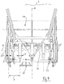
- FIG. 1 shows that the rolling wheels 8 in comparison to known tracking rollers o.
- Support elements have an enlarged diameter D, wherein this to the corresponding Rode righteousness (working height W, Fig. 1), in particular with respect to Height K of the potato trunks 4 is adaptable.
- the two rolling wheels 8, 8 'of a guide unit E have in comparison to the height K of the potato trench 4 by a multiple, in particular 2.5 times, larger diameter D.
- the rolling wheels 8 of the multi-row receiving device 3 are each provided with the same diameter D in the transverse direction.
- the views according to FIG. 4 and FIG. 5 show that the rolling wheels 8 can be provided with different widths Z, Z '.
- the design of the guide unit E provides that between the transversely to the direction of travel F a row forming wheels 8 (support axis Q) a variable, in particular at the distance of the potato trenches 4 adaptable support distance B (Fig. 1) is provided.
- the rolling wheels 8 can be arranged according to the crop or the profile of the potato dam with different support distances (not shown).
- adjusting elements not shown in detail for adjusting the rolling wheels 8 transverse to the direction of travel F so that the rolling wheels 8 are supported by a manual or automatic transverse adjustment in each case optimally in the groove 9 between the potato stems 4.
- a lateral guidance at 6, 7 is achieved on the potato trench 4 and the mixture G can be between the two Rolling wheels 8, 8 'are optimally conducted on a separation line T in the machine 1 (Fig. 2).
- the receiving device 3 has in the direction of movement F of the machine 1 rotatable wheels 8 (arrow C), the potato harvester 1 is moved by means of not shown drive wheels in the direction of travel F total. It is also conceivable to provide the rolling wheels 8 with a separate drive, not shown, so that the effects of the rolling wheels 8, 8 'exemplified in FIGS. 1 and 2 as a pulling aid (here: lateral pressing of the dam 4 according to arrow S, S' and driving effect according to arrow P) are actively supported.
- a pulling aid here: lateral pressing of the dam 4 according to arrow S, S' and driving effect according to arrow P
- the Rodeschare 5 located in the vicinity of the rolling wheels 8 can be optimally adjusted by the guide unit E or a height-adjustable support of the rolling wheels 8 to the height K of the potato trenches 4 and thus the multi-row harvesting process (FIG.
- Fig. 3 to 5 are provided for this purpose constructive details of the receiving device 3, which is provided with a on the one hand with a machine frame 10 connectable and on the other hand in the field of Rodeschare 5 the rolling wheels 8 bearing linkage assembly 11.
- the rolling wheels 8 are rotatably mounted in the direction of travel F on a transverse axis 12 of the linkage assembly 11.
- Fig. 3 shows that the substantially symmetrical to the longitudinal center plane M of the machine 1 constructed linkage assembly 11 is formed as a two-side link 13, 14 and a front cross bar 15 having guiding and steering frame.
- the receiving device 3 by means of respective on the links 13, 14 attacking and in particular in the form of lifting cylinders 16, 17 trained drive elements are actuated.
- the receiving device 3 For a lifting movement according to arrow H (FIG. 2), the receiving device 3 is connected to the machine frame 10 in the region of the links 13, 14 by means of respective support bearings 18, 19, so that the lifting movement H causes a pivoting movement according to arrow R (FIG ,
- the recording device 3 can be lifted altogether, z. B. at the edge of a field or while driving.
- the holder of the rolling wheels 8 centrally supporting transverse axis 12 on the linkage assembly 11 is clear.
- the transverse axis 12 is connected by at least one of these radially extending rocker arm 20 with the front portion of the linkage assembly 11 by means of a support bearing 25.
- the transverse axis 12 can be displaced together with the rolling wheels 8 by at least one further lifting member in the form of a lifting cylinder 21 (arrow N).
- the movement of the lifting cylinder 21 is introduced on the short arm 26 of the rocker arm 20, deflected by the support bearing 27 and transmitted to the support bearing 28, so that in particular a change in position of the assembly E relative to the linkage assembly 11 takes place (arrow N).
- Fig. 3 to 5 illustrates that the transverse axis 12 in symmetrical construction of the device 3 each end in the region of the support bearing 27, 27 'is connected to the linkage assembly 11 and each provided as a connector lifting members in the form of two parallel lifting cylinders 21, 21' with the respective rocker arm 20, 20 'cooperate so that the pivoting and adjusting movement according to arrow N is possible.
- This influenced by a control of the machine 1 pivotal movement N is used in the simplest version as a depth control. Even during the Rodevorgang a largely arbitrary adjustment of the lifting cylinder 21, 21 'is conceivable.
- the displacement of the rolling wheels 8 defines the height effective as a depth of discharge height distance to the Rodescharen. 5
- the plan view according to FIG. 4 shows an additional button unit 23, which is provided as an assembly for controlling the receiving device 3 or the lifting units 2 in the area of the rolling wheels 8, which can be placed on one of the potato trenches 4. It is also conceivable that in the area of the rolling wheels 8 a measuring device 22 is provided, with which the receiving depth of the receiving device 3 can be controlled and controlled.
- the potato harvesting machine 1 is designed for use in sloping terrain so that the receiving device 3 largely independent of the cab, the collection bunker o. The like. Assemblies (not shown) in the direction indicated by arrow W '(FIG. 3) about the central longitudinal plane M is pivotally , The control of the direction of travel F according to the course of the potato trenches 4 can be done manually by the driver of the machine. With the measuring device 22, a control or control of this process is possible, so that the side control of the machine 1 can be optimized by a corresponding measurement signal of the device 22. For this largely automatic centering on the potato ridge and the rolling wheels 8 according to the invention are available. In this case, the forces acting in the direction S, S '(FIG.
- FIGS. 6 and 7 show a further embodiment of the receiving device 3, the latter being provided in the region of the two outer rolling wheels 8 "with a cutting element generally designated 28 (FIG. 5: Secharchitecture 28 'as a cutting member).
- a cutting element 29 which can be directly connected to the rolling wheels 8 "is provided as a cutting member 28, the cutting action of which is effected directly by the pressure or weight force according to arrow A (FIG a separation of protruding into the marginal ridge plant parts such as potato herb or the like is achieved .
- a cutting edge 29 is a cutting edge 30 forming, in particular multi-membered annular disc 31 is provided with the respective rolling wheel 8 "connected, which is also conceivable to arrange an annular disc centered on the rolling wheel 8" (not shown).
- rolling wheels 8 with cutting member 28 is conceivable that the rolling wheels 8" directly and / or the associated cutting member 28 in the direction of the support beam 15 and the transverse axis 12 is transversely adjustable by a corresponding bracket / are (not shown), so that an optimal adjustment of the receiving device 3 is possible according to the harvesting conditions.
Landscapes
- Life Sciences & Earth Sciences (AREA)
- Environmental Sciences (AREA)
- Harvesting Machines For Root Crops (AREA)
- Preparation Of Fruits And Vegetables (AREA)
- Transplanting Machines (AREA)
- Harvesting Machines For Specific Crops (AREA)
- Agricultural Machines (AREA)
Abstract
Description
- Die Erfindung betrifft eine Kartoffelerntemaschine gemäß dem Oberbegriff des Anspruchs 1.
- Kartoffelerntemaschinen bekannter Ausführung sind mit einer zumindest ein Rodeaggregat aufweisenden Aufnahmevorrichtung zum Aufnehmen des Kartoffeldamms versehen, wobei die am Maschinengestell gehaltene Aufnahmevorrichtung durch zumindest ein Auflageelement bodenseitig abstützbar ist. Gemäß
DE 25 10 455 ist das Maschinengestell über Laufräder abgestützt und inDE 32 00 924 A1 ist im Bereich der Aufnahmevorrichtung eine auf dem Kartoffeldamm auflegbare Dammtrommel vorgesehen. Auch die Kartoffelerntemaschinen gemäßG 87 00 095.4 undDE 199 47 484 A1 weisen im Bereich der Rodeschare eine bodenseitige Dammrolle bzw. -trommel auf. Bei einer einreihigen Erntemaschine gemäßJP 07107828 A - Bei einer Maschine gemäß
DE 32 07 288 C2 ist bei einem einreihigen Kartoffelroder ein im Bereich des vorderen Randes des Aufnahmeschares mitführbares Tiefenrad vorgesehen. Dieses dient zur Tiefensteuerung und wird gleichzeitig zum Abschneiden von Kartoffelkraut genutzt. Auch in der Fachliteratur wird allgemein vorgeschlagen, zusätzlich zur Abtastung mittels Dammtrommeln o. dgl. Bauteile eine Tiefenführung der Rodeschar mit einem ohne Stützlast in der Furche mitlaufenden Stützrad zu verwenden. - Der Erfindung liegt die Aufgabe zugrunde, eine Kartoffelerntemaschine zu schaffen, deren Aufnahmevorrichtung eine für den Einstell- und Rodevorgang der Schare optimale Abstützung aufweist und dabei mit geringem technischen Aufwand eine Verbesserung der Rodeleistung ermöglicht.
- Die Erfindung löst diese Aufgabe durch eine Kartoffelerntemaschine mit den Merkmalen des Anspruchs 1. Hinsichtlich weiterer Vorteile und Ausgestaltungen wird auf die Ansprüche 2 bis 27 verwiesen.
- Die Kartoffelerntemaschine weist im Bereich der mit zumindest einem Rodeaggregat versehenen Aufnahmevorrichtung ein Auflageelement auf, das erfindungsgemäß von zumindest zwei entlang gegenüberliegender Seitenränder eines zwischenliegenden Kartoffeldamms verlagerbaren und als eine funktionale Einheit zusammenwirkenden Rollrädern gebildet ist.
- In Abgrenzung zu an sich bekannten Dammtrommeln, Tasträdern o. dgl. Auflageelementen zur Tiefenführung von Aufnahmevorrichtungen bekannter Art ist die die beiden Rollräder aufweisende Führungseinheit so konzipiert, daß in den beiden Furchen neben dem zumindest einen Kartoffeldamm eine die Gewichtskraft der Aufnahmevorrichtung aufnehmende Abstützung erreicht ist. Mit geringem Aufwand sind die Rollräder auch für eine Tiefeneinstellung bzw. -steuerung der Rodeschare nutzbar. Die einen auf die jeweilige Breite des Kartoffeldamms abstimmbaren Querabstand aufweisenden Rollräder begrenzen in der Rodephase den Kartoffeldamm, so daß für den Fördervorgang eine Zwangsführung nach Art eines Einzugskanals bewirkt ist. Das seitlich geführte Rodematerial wird als ein stabilisierter Gemischstrom in die nachfolgende Trennstrecke eingeleitet, so daß damit die Zuführung des aufgenommenen Kartoffeldamms in nachgeordnete Aggregate der Maschine insgesamt verbessert ist. Diese Rollräder sind dabei als kombinierte Stütz-, Führungs- und Steuerelemente nutzbar, so daß die Aufnahmevorrichtung als eine funktional verbesserte Baueinheit bereitgestellt wird. Zusätzlich können die äußeren der Rollräder mit Schneidelementen versehen sein, so daß in den Aufnahmebereich ragendes Kartoffelkraut o. dgl. Pflanzenteile abgetrennt werden.
- Durch eine weitgehend variable Gestaltung der Verbindungsbaugruppen zwischen den Rollrädern und einem Traggestell der Aufnahmevorrichtung sind unterschiedliche Antriebs- und Stützkonstruktionen sowie jeweilige Höhen- und Querverstellmöglichkeiten der Rollräder denkbar, so daß die Konstruktion insgesamt ein an die jeweiligen Rodebedingungen variabel anpaßbares System bildet.
- Weitere Einzelheiten und vorteilhafte Ausgestaltungen der erfindungsgemäßen Kartoffelerntemaschine ergeben sich aus der nachfolgenden Beschreibung und der Zeichnung. In der Zeichnung zeigen:
- Fig. 1
- eine perspektivische Prinzipdarstellung der Kartoffelerntemaschine im Bereich der Aufnahmevorrichtung mit erfindungsgemäßen Rollrädern,
- Fig. 2
- eine Seitenansicht der Kartoffelerntemaschine ähnlich Fig. 1 mit einer Aufnahmephase eines der Kartoffeldämme,
- Fig. 3
- eine Perspektivdarstellung der Aufnahmevorrichtung ähnlich Fig. 1 mit zusätzlichen Baugruppen im Bereich der Rollräder,
- Fig. 4
- eine Draufsicht der Aufnahmevorrichtung gemäß Fig. 3,
- Fig. 5
- eine Vorderansicht der Aufnahmevorrichtung gemäß Fig. 4,
- Fig. 6
- eine Vorderansicht ähnlich Fig. 4 mit der veränderte seitliche Rollräder aufweisenden Aufnahmevorrichtung, und
- Fig. 7
- eine Perspektivdarstellung der Aufnahmevorrichtung gemäß Fig. 6.
- In Fig. 1 ist eine insgesamt mit 1 bezeichnete Kartoffelerntemaschine dargestellt, deren Aufbau nur schematisch angedeutet ist. Im vorderen Bereich ist die Maschine 1 mit einer zumindest ein Rodeaggregat 2 aufweisenden Aufnahmevorrichtung 3 zum Aufnehmen von Kartoffeldämmen 4 versehen. Bei bekannten Kartoffelerntemaschinen 1 dieser Art wird die ein oder mehrere Rodeschar(e) 5 aufweisende Aufnahmevorrichtung 3 durch zumindest ein als Auflagetrommel o. dgl. ausgebildetes Auflageelement (nicht dargestellt) bodenseitig, insbesondere im Bereich des Kartoffeldamms 4, abgestützt.
- Die Kartoffelerntemaschine 1 ist erfindungsgemäß mit einer Aufnahmevorrichtung 3 versehen, die zumindest zwei entlang gegenüberliegender Seitenränder 6, 7 des zwischenliegenden Kartoffeldamms 4 verlagerbare Rollräder 8, 8' aufweist, die nach Art von multifunktionellen Auflageelementen wirksam sind.
- Bei der gemäß Fig. 1 bis 5 dargestellten Ausführung der Kartoffelerntemaschine 1 ist die Aufnahmevorrichtung 3 als eine mehrreihige Baugruppe vorgesehen. Bei dieser mehrreihigen, vorzugsweise 4-reihigen, Aufnahmevorrichtung 3 ist die Anzahl der paarweise zusammenwirkenden Rollräder 8 jeweils um eines höher als die Anzahl der aufzunehmenden Kartoffeldämme 4, so daß sich bei dieser Ausführung zur Rodung von vier Kartoffeldämmen 4 eine Aufnahmevorrichtung 3 mit fünf quer zur Fahrtrichtung F aneinandergereihten Rollrädern 8 (Fig. 1, Fig. 3) ergibt.
- Die beiden jeweils zusammenwirkenden Rollräder 8, 8' bilden damit eine zumindest einen Anteil der Gewichtskraft A des Rodeaggregates 2 abstützende, zur Steuerung der Rodeschare 5 vorgesehene und am aufzunehmenden Kartoffeldamm 4 als eine Einzugshilfe wirksame Führungseinheit E. In der dargestellten Ausführung mit fünf Rollrädern 8 ist die Gewichtskraft A entsprechend mehrreihig verteilt, so daß die bodenseitige Flächenpressung je Rollrad 8 durch entsprechende Verteilung reduziert ist.
- Aus der Ansicht gemäß Fig. 1 ergibt sich, daß die Rollräder 8 im Vergleich zu bekannten Tastrollen o. dgl. Auflageelementen einen vergrößerten Durchmesser D aufweisen, wobei dieser an die entsprechenden Rodebedingungen (Arbeitshöhe W, Fig. 1), insbesondere in Bezug auf die Höhe K der Kartoffeldämme 4 anpaßbar ist. Die beiden Rollräder 8, 8' einer Führungseinheit E weisen im Vergleich zur Höhe K des Kartoffeldamms 4 einen um ein Vielfaches, insbesondere das 2,5-fache, größeren Durchmesser D auf. Dabei sind die Rollräder 8 der mehrreihigen Aufnahmevorrichtung 3 in Querrichtung jeweils mit dem gleichen Durchmesser D versehen. Die Ansichten gemäß Fig. 4 und Fig. 5 zeigen, daß die Rollräder 8 mit unterschiedlicher Breite Z, Z' versehen sein können.
- Die Konstruktion der Führungseinheit E sieht vor, daß zwischen den quer zur Fahrtrichtung F eine Reihe bildenden Rollrädern 8 (Stützachse Q) ein variierbarer, insbesondere an den Abstand der Kartoffeldämme 4 anpaßbarer Stützabstand B (Fig. 1) vorgesehen ist. Die Rollräder 8 können entsprechend dem Erntegut bzw. dem Profil des Kartoffeldamms mit unterschiedlichen Stützabständen angeordnet werden (nicht dargestellt). Denkbar sind auch nicht näher dargestellte Stellelemente zur Verstellung der Rollräder 8 quer zur Fahrtrichtung F, so daß die Rollräder 8 durch eine manuelle oder automatische Querverstellung jeweils optimal in der Furche 9 zwischen den Kartoffeldämmen 4 abgestützt sind. In jedem Fall wird am Kartoffeldamm 4 eine seitliche Führung bei 6, 7 erreicht und das Gemisch G kann zwischen den beiden Rollrädern 8, 8' optimal auf einer Trennstrecke T in die Maschine 1 geleitet werden (Fig. 2).
- Die Aufnahmevorrichtung 3 weist in Bewegungsrichtung F der Maschine 1 drehbare Rollräder 8 (Pfeil C) auf, wobei die Kartoffelerntemaschine 1 insgesamt mittels nicht dargestellter Antriebsräder in Fahrtrichtung F bewegt wird. Denkbar ist auch, die Rollräder 8 mit einem nicht dargestellten separaten Antrieb zu versehen, so daß die in Fig. 1 und 2 beispielhaft dargestellten Wirkungen der Rollräder 8, 8' als Einzugshilfe (hier: seitliche Pressung des Dammes 4 gemäß Pfeil S, S' und Mitnahmewirkung gemäß Pfeil P) aktiv unterstützbar sind.
- Die im Nahbereich der Rollräder 8 befindlichen Rodeschare 5 können durch die Führungseinheit E bzw. eine höhenverstellbare Abstützung der Rollräder 8 optimal auf die Höhe K der Kartoffeldämme 4 und damit den mehrreihigen Rodevorgang (Fig. 2) eingestellt werden.
- Aus Fig. 3 bis 5 ergeben sich dafür vorgesehene konstruktive Einzelheiten der Aufnahmevorrichtung 3, wobei diese mit einer einerseits mit einem Maschinengestell 10 verbindbaren und andererseits im Bereich der Rodeschare 5 die Rollräder 8 tragenden Gestängebaugruppe 11 versehen ist. Die Rollräder 8 sind dabei in Fahrtrichtung F drehbar an einer Querachse 12 der Gestängebaugruppe 11 gelagert. Fig. 3 zeigt, daß die im wesentlichen symmetrisch zur Längsmittelebene M der Maschine 1 aufgebaute Gestängebaugruppe 11 als ein zwei seitliche Lenker 13, 14 und einen vorderen Querbalken 15 aufweisender Führungs- und Lenkrahmen ausgebildet ist.
- Damit kann die Aufnahmevorrichtung 3 mittels jeweiliger an den Lenkern 13, 14 angreifender und insbesondere in Form von Hubzylindern 16, 17 ausgebildeter Antriebselemente betätigt werden. Für eine Hubbewegung gemäß Pfeil H (Fig. 2) ist die Aufnahmevorrichtung 3 im Bereich der Lenker 13, 14 mittels jeweiliger Stützlager 18, 19 so mit dem Maschinengestell 10 verbunden, daß die Hubbewegung H eine Schwenkbewegung gemäß Pfeil R (Fig. 2) bewirkt. Damit kann die Aufnahmevorrichtung 3 insgesamt abgehoben werden, z. B. am Rand eines Feldes oder bei der Fahrt.
- Aus der Seitenansicht gemäß Fig. 2 und der Vorderansicht gemäß Fig. 5 wird die Halterung der die Rollräder 8 zentral tragenden Querachse 12 an der Gestängebaugruppe 11 deutlich. Die Querachse 12 ist durch zumindest einen von dieser aus radial verlaufenden Schwinghebel 20 mit dem vorderen Bereich der Gestängebaugruppe 11 mittels eines Stützlagers 25 verbunden. Mit diesem Schwinghebel 20 kann die Querachse 12 gemeinsam mit den Rollrädern 8 durch zumindest ein weiteres Huborgan in Form eines Hubzylinders 21 verlagert werden (Pfeil N). Die Bewegung des Hubzylinders 21 wird am kurzen Arm 26 des Schwinghebels 20 eingeleitet, durch dessen Traglager 27 umgelenkt und auf das Stützlager 28 übertragen, so daß insbesondere eine Lageänderung der Baueinheit E relativ zur Gestängebaugruppe 11 erfolgt (Pfeil N).
- Die Zusammenschau von Fig. 3 bis 5 verdeutlicht, daß die Querachse 12 bei symmetrischem Aufbau der Vorrichtung 3 jeweils endseitig im Bereich des Traglagers 27, 27' mit der Gestängebaugruppe 11 verbunden ist und die jeweils als Verbinder vorgesehenen Huborgane in Form von zwei parallelen Hubzylindern 21, 21' mit dem jeweiligen Schwinghebel 20, 20' so zusammenwirken, daß die Schwenk- und Einstellbewegung gemäß Pfeil N möglich ist. Diese über eine Steuerung der Maschine 1 beeinflußbare Schwenkbewegung N wird in einfachster Ausführung als Tiefensteuerung genutzt. Auch während dem Rodevorgang ist eine weitgehend beliebige Verstellung der Hubzylinder 21, 21' denkbar. Die Verlagerung der Rollräder 8 definiert dabei den als Rodetiefe wirksamen Höhenabstand zu den Rodescharen 5.
- Die Draufsicht gemäß Fig. 4 zeigt eine zusätzliche Tasteinheit 23, die als auf einem der Kartoffeldämme 4 auflegbare Baugruppe zur Steuerung der Aufnahmevorrichtung 3 bzw. der Rodeaggregate 2 im Bereich der Rollräder 8 vorgesehen ist. Denkbar ist auch, daß im Bereich der Rollräder 8 eine Meßeinrichtung 22 vorgesehen ist, mit der die Aufnahmetiefe der Aufnahmevorrichtung 3 kontrollierbar und steuerbar ist.
- Die Kartoffelerntemaschine 1 ist für den Einsatz in hangigem Gelände so ausgebildet, daß die Aufnahmevorrichtung 3 weitgehend unabhängig vom Führerhaus, dem Sammelbunker o. dgl. Baugruppen (nicht dargestellt) in Richtung gemäß Pfeil W' (Fig. 3) um die Mittellängsebene M schwenkbar ist. Die Steuerung der Fahrtrichtung F entsprechend dem Verlauf der Kartoffeldämme 4 kann dabei manuell vom Fahrer der Maschine erfolgen. Mit der Meßeinrichtung 22 ist auch eine Kontrolle oder Steuerung dieses Vorgangs möglich, so daß die Seitensteuerung der Maschine 1 durch ein entsprechendes Meßsignal der Einrichtung 22 optimiert werden kann. Für diese weitgehend automatische Zentrierung auf dem Kartoffeldamm sind auch die erfindungsgemäßen Rollräder 8 nutzbar. Als Führungsgröße können dabei die in Richtung S, S' (Fig. 1) wirksamen Kräfte genutzt werden, wobei mittels jeweiliger Sensoren (nicht dargestellt) im Bereich der seitlichen Schwinghebel 20, 20' jeweilige seitliche Belastungen erfaßbar sind und durch deren Minimierung wird die Aufnahmevorrichtung 3 optimal entsprechend dem Verlauf der Kartoffeldämme 4 geführt.
- In Fig. 6 und 7 ist eine weitere Ausführungsform der Aufnahmevorrichtung 3 dargestellt, wobei diese im Bereich der beiden äußeren Rollräder 8" mit einem allgemein mit 28 bezeichneten Schneidorgan (Fig. 5: Sechscheibe 28' als Schneidorgan) versehen ist.
- In vorteilhafter Ausführung ist als Schneidorgan 28 ein mit den Rollrädern 8" unmittelbar verbindbares Schneidglied 29 (Fig. 6) vorgesehen, dessen Schneidwirkung damit unmittelbar durch die Druck- bzw. Gewichtskraft gemäß Pfeil A (Fig. 2) bewirkt wird. Mit dem Schneidglied 29 wird eine Abtrennung von in die Randfurche ragenden Pflanzenteilen wie Kartoffelkraut o. dgl. erreicht. In der Perspektivdarstellung gemäß Fig. 7 wird deutlich, daß als Schneidglied 29 eine eine Schneidkante 30 bildende, insbesondere mehrgliedrige Ringscheibe 31 vorgesehen ist. Diese Ringscheibe 31 ist unmittelbar randseitig mit dem jeweiligen Rollrad 8" verbunden, wobei ebenfalls denkbar ist, eine Ringscheibe mittig auf dem Rollrad 8" anzuordnen (nicht dargestellt).
- In einer weiteren Ausführung dieser Rollräder 8" mit Schneidorgan 28 ist denkbar, daß die Rollräder 8" direkt und/oder das zugeordnete Schneidorgan 28 in Richtung des Tragbalkens 15 bzw. der Querachse 12 durch eine entsprechende Halterung quereinstellbar ist/sind (nicht dargestellt), so daß entsprechend den Erntebedingungen eine optimale Einstellung der Aufnahmevorrichtung 3 möglich ist.
Claims (27)
- Kartoffelerntemaschine mit einer zumindest ein Rodeaggregat (2) aufweisenden Aufnahmevorrichtung (3) zum Aufnehmen von Kartoffeldämmen (4), wobei die ein oder mehrere Rodeschar(e) (5) aufweisende Aufnahmevorrichtung (3) durch zumindest ein zusätzliches Auflageelement bodenseitig abstützbar ist, dadurch gekennzeichnet, daß das Auflageelement von zumindest zwei entlang gegenüberliegender Seitenränder (6, 7) eines zwischenliegenden Kartoffeldamms (4) verlagerbaren Rollrädern (8, 8') gebildet ist.
- Kartoffelerntemaschine nach Anspruch 1, dadurch gekennzeichnet, daß die beiden Rollräder (8, 8') eine zumindest einen Anteil des Gewichts (A) des Rodeaggregates (2) abstützende, zur Steuerung der Rodeschare (5) vorgesehene und am aufzunehmenden Kartoffeldamm (4) als Einzugshilfe (Pfeil S, S', P) wirksame Führungseinheit (E) bilden.
- Kartoffelerntemaschine nach Anspruch 1 oder 2, dadurch gekennzeichnet, daß bei einer mehrreihigen, vorzugsweise 4-reihigen Aufnahmevorrichtung (3) die Anzahl der Rollräder (8) jeweils um eines höher ist als die Anzahl der aufzunehmenden Kartoffeldämme (4).
- Kartoffelerntemaschine nach einem der Ansprüche 1 bis 3, dadurch gekennzeichnet, daß die Rollräder (8) einen entsprechend den Rodebedingungen (K) bemeßbaren Durchmesser (D) aufweisen.
- Kartoffelerntemaschine nach einem der Ansprüche 1 bis 4, dadurch gekennzeichnet, daß die Rollräder (8) einen im Vergleich zur Höhe des Kartoffeldamms (4) um ein Vielfaches, insbesondere das 2,5-fache, größeren Durchmesser (D) aufweisen.
- Kartoffelerntemaschine nach einem der Ansprüche 1 bis 5, dadurch gekennzeichnet, daß bei einer mehrreihigen Aufnahmevorrichtung (3) die Rollräder (8) jeweils den gleichen Durchmesser (D) aufweisen.
- Kartoffelerntemaschine nach einem der Ansprüche 1 bis 6, dadurch gekennzeichnet, daß zwischen den quer zur Fahrtrichtung (F) eine Reihe bildenden Rollrädern (8) ein variierbarer, insbesondere an den Abstand der Kartoffeldämme (4) anpaßbarer Stützabstand (B) vorgesehen ist.
- Kartoffelerntemaschine nach Anspruch 7, dadurch gekennzeichnet, daß die Rollräder (8) mit unterschiedlichem Stützabstand angeordnet sind.
- Kartoffelerntemaschine nach einem der Ansprüche 1 bis 8, dadurch gekennzeichnet, daß die Rollräder (8) antreibbar sind.
- Kartoffelerntemaschine nach einem der Ansprüche 1 bis 9, dadurch gekennzeichnet, daß die Rollräder (8) höheneinstellbar (Pfeil N) sind.
- Kartoffelerntemaschine nach einem der Ansprüche 1 bis 10, dadurch gekennzeichnet, daß die Rollräder (8) quer zur Fahrtrichtung (F) verstellbar sind.
- Kartoffelerntemaschine nach Anspruch 10, dadurch gekennzeichnet, daß die Rollräder (8) durch Querverstellung in einer jeweils zwischen den Kartoffeldämmen (4) vorgesehenen Furche (9) abstützbar sind.
- Kartoffelerntemaschine nach einem der Ansprüche 1 bis 12, dadurch gekennzeichnet, daß im Bereich der Rollräder (8) eine Meßeinrichtung (22) vorgesehen ist, mit der die Aufnahmetiefe der Aufnahmevorrichtung (3) bzw. des jeweiligen Rodeschars (5) steuerbar ist.
- Kartoffelerntemaschine nach einem der Ansprüche 1 bis 13, dadurch gekennzeichnet, daß die Aufnahmevorrichtung (3) bzw. das Rodeaggregat (2) im Bereich der Rollräder (8) mit zumindest einer auf einem der Kartoffeldämme (4) auflegbaren Tasteinheit (23) versehen ist.
- Kartoffelerntemaschine nach einem der Ansprüche 1 bis 14, dadurch gekennzeichnet, daß die Aufnahmevorrichtung (3) mit einer diese einerseits mit einem Maschinengestell (10) verbindenden und andererseits im Bereich der Rodeschare (5) die Rollräder (8) tragenden Gestängebaugruppe (11) versehen ist.
- Kartoffelerntemaschine nach einem der Ansprüche 1 bis 15, dadurch gekennzeichnet, daß die Rollräder (8) in Fahrtrichtung drehbar an einer Querachse (12) der Gestängebaugruppe (11) gelagert sind.
- Kartoffelerntemaschine nach einem der Ansprüche 1 bis 16, dadurch gekennzeichnet, daß die im wesentlichen symmetrisch zur Längsmittelebene (M) der Maschine (1) aufgebaute Gestängebaugruppe (11) als ein zwei seitliche Lenker (13, 14) und einen vorderen Querbalken (15) aufweisender Rahmen ausgebildet ist, derart, daß die Aufnahmevorrichtung (3) mittels jeweiliger an den Lenkern (13, 14) angreifender Hubzylinder (15, 16) und jeweiliger im Abstand zu diesen vorgesehener Stützlager (18, 19) insgesamt schwenkbar mit dem Maschinengestell (10) verbunden ist.
- Kartoffelerntemaschine nach einem der Ansprüche 1 bis 17, dadurch gekennzeichnet, daß die die Rollräder (8) zentral tragende Querachse (12) durch zumindest einen von dieser aus radial verlaufenden Schwinghebel (20, 20') an der Gestängebaugruppe (11) gelagert ist, derart, daß die Querachse (12) gemeinsam mit den Rollrädern (8) durch zumindest ein Huborgan (21) verlagerbar ist.
- Kartoffelerntemaschine nach Anspruch 18, dadurch gekennzeichnet, daß die Querachse (12) jeweils endseitig im Bereich eines Gelenkes (27, 27') mit der Gestängebaugruppe (11) verbunden ist und die als Verbinder vorgesehenen Huborgane (21, 21') in Form von zwei parallelen Hubzylindern mit dem jeweiligen Schwinghebel (20, 20') zusammenwirken.
- Kartoffelerntemaschine nach einem der Ansprüche 1 bis 19, dadurch gekennzeichnet, daß die Rollräder (8) mit einer zur automatischen Führung der Aufnahmevorrichtung (3) entlang der Kartoffeldämme (4) vorgesehenen Meßeinrichtung (22, 23) zusammenwirken.
- Kartoffelerntemaschine nach Anspruch 20, dadurch gekennzeichnet, daß die Meßeinrichtung jeweilige an den Tragteilen der Rollräder (8) befindliche Sensoren aufweist.
- Kartoffelerntemaschine nach Anspruch 20 oder 21, dadurch gekennzeichnet, daß die Meßeinrichtung jeweilige an zumindest einem der beiden Schwinghebel (20, 20') wirksame Seitenkräfte (S, S') erfassende Sensoren aufweist.
- Kartoffelerntemaschine nach einem der Ansprüche 1 bis 22, dadurch gekennzeichnet, daß zumindest die äußeren der Rollräder (8") mit einem Schneidorgan (28, 28') zusammenwirken.
- Kartoffelerntemaschine nach Anspruch 23, dadurch gekennzeichnet, daß als Schneidorgan (28) ein auf den Rollrädern (8") befindliches Schneidglied (29) vorgesehen ist.
- Kartoffelerntemaschine nach Anspruch 23 oder 24, dadurch gekennzeichnet, daß als Schneidglied (29) eine eine Schneidkante (30) aufweisende Ringscheibe (31) vorgesehen ist.
- Kartoffelerntemaschine nach einem der Ansprüche 23 bis 25, dadurch gekennzeichnet, daß die Ringscheibe (31) unmittelbar randseitig oder mittig mit dem Rollrad (8") verbunden ist.
- Kartoffelerntemaschine nach einem der Ansprüche 23 bis 26, dadurch gekennzeichnet, daß das jeweilige äußere Rollrad (8") und/oder das Schneidorgan (28) in Richtung der Querachse (12) und/oder der Schnittiefe einstellbar ist/sind.
Priority Applications (1)
| Application Number | Priority Date | Filing Date | Title |
|---|---|---|---|
| PL07014151T PL1880591T3 (pl) | 2006-07-22 | 2007-07-19 | Maszyna do zbioru ziemniaków |
Applications Claiming Priority (1)
| Application Number | Priority Date | Filing Date | Title |
|---|---|---|---|
| DE102006033974A DE102006033974A1 (de) | 2006-07-22 | 2006-07-22 | Kartoffelerntemaschine |
Publications (2)
| Publication Number | Publication Date |
|---|---|
| EP1880591A1 true EP1880591A1 (de) | 2008-01-23 |
| EP1880591B1 EP1880591B1 (de) | 2009-09-09 |
Family
ID=38472825
Family Applications (1)
| Application Number | Title | Priority Date | Filing Date |
|---|---|---|---|
| EP07014151A Active EP1880591B1 (de) | 2006-07-22 | 2007-07-19 | Kartoffelerntemaschine |
Country Status (10)
| Country | Link |
|---|---|
| US (2) | US20080017394A1 (de) |
| EP (1) | EP1880591B1 (de) |
| AT (1) | ATE442030T1 (de) |
| CA (1) | CA2594225C (de) |
| DE (2) | DE102006033974A1 (de) |
| DK (1) | DK1880591T3 (de) |
| EA (1) | EA012343B1 (de) |
| ES (1) | ES2330893T3 (de) |
| PL (1) | PL1880591T3 (de) |
| UA (1) | UA93866C2 (de) |
Cited By (2)
| Publication number | Priority date | Publication date | Assignee | Title |
|---|---|---|---|---|
| EP2591660A1 (de) | 2011-11-11 | 2013-05-15 | Grimme Landmaschinenfabrik GmbH & Co. KG | Erntemaschine für insbesondere Hackfrüchte |
| CN105052339A (zh) * | 2015-08-21 | 2015-11-18 | 中机美诺科技股份有限公司 | 一种可实现后方铺放作业的马铃薯收获机 |
Families Citing this family (13)
| Publication number | Priority date | Publication date | Assignee | Title |
|---|---|---|---|---|
| CN102160491A (zh) * | 2010-02-17 | 2011-08-24 | 崔祥联 | 甘薯生姜挖掘机 |
| US8910724B2 (en) * | 2012-01-16 | 2014-12-16 | Spudnik Equipment Co., Llc | Telescoping coulter system and method |
| DE102012104525A1 (de) * | 2012-05-25 | 2013-11-28 | Claas Selbstfahrende Erntemaschinen Gmbh | Landwirtschaftliche Erntemaschine |
| CN103392392B (zh) * | 2013-07-02 | 2016-08-10 | 邓光辉 | 一种新型起垄机 |
| CN105009775B (zh) * | 2015-07-27 | 2017-03-29 | 农业部南京农业机械化研究所 | 一种多功能自走式薯类联合收获机 |
| DE102016012245B4 (de) | 2016-10-14 | 2018-04-26 | Grimme Landmaschinenfabrik Gmbh & Co. Kg | Hackfruchternter in Form einer Kartoffelerntemaschine |
| RU185127U1 (ru) * | 2018-04-19 | 2018-11-22 | Федеральное государственное бюджетное образовательное учреждение высшего образования "Рязанский государственный агротехнологический университет имени П.А. Костычева" | Картофелекопатель |
| RU194510U1 (ru) * | 2019-08-23 | 2019-12-12 | Федеральное государственное бюджетное образовательное учреждение высшего образования "Рязанский государственный агротехнологический университет имени П.А. Костычева" | Каток опорный картофелеуборочного комбайна |
| CN111642220B (zh) * | 2020-06-24 | 2022-06-03 | 萧县威辰机电工程设备有限公司 | 一种带回收功能的马铃薯收获装置 |
| WO2022054074A1 (en) | 2020-09-11 | 2022-03-17 | Shaktiman Grimme Root Crop Solutions Private Limited | A pull type tractor driven root crop digger cum harvester |
| CN112930831A (zh) * | 2021-03-25 | 2021-06-11 | 山东明沃机械有限公司 | 马铃薯收获机 |
| CN116711525A (zh) * | 2023-06-26 | 2023-09-08 | 重庆好帮手农机科技有限公司 | 一种马铃薯定量上料机构及收割机 |
| CN119318263B (zh) * | 2023-07-17 | 2025-10-24 | 中国农业机械化科学研究院集团有限公司 | 一种马铃薯自适应捡拾方法及装置 |
Citations (3)
| Publication number | Priority date | Publication date | Assignee | Title |
|---|---|---|---|---|
| DE2510455A1 (de) * | 1975-03-11 | 1976-09-23 | Grimme Landmaschf Franz | Selbstfahrende kartoffelerntemaschine |
| EP0719495A1 (de) * | 1994-12-27 | 1996-07-03 | Amac B.V. | Erntemaschine |
| EP1205099A1 (de) * | 2000-11-09 | 2002-05-15 | Franz Grimme Landmaschinenfabrik GmbH & Co. KG. | Kartoffelerntemaschine |
Family Cites Families (45)
| Publication number | Priority date | Publication date | Assignee | Title |
|---|---|---|---|---|
| US498885A (en) * | 1893-06-06 | Potato-digger | ||
| US151778A (en) * | 1874-06-09 | Improvement in potato-diggers | ||
| US587725A (en) * | 1897-08-10 | Potato-digging machine | ||
| US408208A (en) * | 1889-08-06 | Potato-digger | ||
| US969690A (en) * | 1910-03-11 | 1910-09-06 | Walter F Headland | Potato-digger. |
| US1293144A (en) * | 1918-03-15 | 1919-02-04 | Vergil P Mckinley | Peanut-digger. |
| US1761286A (en) * | 1927-02-21 | 1930-06-03 | Roscoe C Zuckerman | Potato-digging machine |
| US2110997A (en) * | 1936-03-25 | 1938-03-15 | Mayfield Clement Shelton | Soil cleaner |
| US2417580A (en) * | 1944-03-15 | 1947-03-18 | Syracuse Chilled Plow Co Inc | Potato digger with power lift |
| GB584502A (en) * | 1944-05-19 | 1947-01-16 | Percival James Packman | Improvements in or relating to potato harvesting machines |
| US2532169A (en) * | 1945-12-20 | 1950-11-28 | Jones Vivian Duff | Potato harvesting machine |
| US2519761A (en) * | 1947-02-19 | 1950-08-22 | John R Hobbs | Potato digger |
| US2537198A (en) * | 1948-03-01 | 1951-01-09 | Clifford C Wetzel | Harvesting machine for potato diggers and the like |
| US2693068A (en) * | 1952-03-25 | 1954-11-02 | Fritz J Rodin | Potato digging and separating machine |
| US3065800A (en) * | 1960-06-20 | 1962-11-27 | Int Harvester Co | Potato digging and harvesting device |
| US3106249A (en) * | 1960-08-22 | 1963-10-08 | Ross H Zachery | Harvester for potatoes and the like |
| US3196599A (en) * | 1963-05-20 | 1965-07-27 | Elmo R Meiners | Automatic height control system |
| US3628609A (en) * | 1969-08-11 | 1971-12-21 | Wilbur H Graybill | Harvesting machine |
| US3743023A (en) * | 1971-10-07 | 1973-07-03 | Hesston Corp | Control for ground tools of farm implements |
| SU427666A2 (ru) * | 1972-05-03 | 1974-05-15 | И. Р. Размыслович | Картофелеуборочный комбайн |
| US3756322A (en) * | 1972-08-25 | 1973-09-04 | J Kopasz | Underground vegetable harvester |
| NL174213C (nl) * | 1974-04-23 | 1984-05-16 | Lely Nv C Van Der | Combinatie van een grondbewerkingsmachine en een machine voor het in de grond brengen van materiaal. |
| US4121667A (en) * | 1976-10-04 | 1978-10-24 | Curl Robert B | Potato harvester |
| US4142585A (en) * | 1977-09-20 | 1979-03-06 | Veb Weimar Werk, Stammbetrieb Des Veb Weimar Kombinat | Digger assembly for root-crop harvester |
| NO147499C (no) | 1981-03-24 | 1983-04-27 | Underhaugs Fabrikk As | Anordning ved potetopptager. |
| DE3200924A1 (de) | 1982-01-14 | 1983-07-21 | Franz Grimme Landmaschinenfabrik Gmbh & Co Kg, 2845 Damme | Kartoffelerntemaschine |
| US4416334A (en) * | 1982-09-28 | 1983-11-22 | Bouillon Alain M | Potato harvesting apparatus |
| DK157590C (da) * | 1984-02-29 | 1990-06-18 | Jens Peter Kvistgaard | Optager, navnlig til optagning af kartofler og andre, navnlig underjordiske, planteprodukter som sellerier, guleroedder, blomster- som spiseloeg, etc. |
| US4796711A (en) * | 1985-04-11 | 1989-01-10 | Row Runner Corp. Of America | Apparatus for removing plastic film from raised plant beds |
| DE3529464C1 (de) * | 1985-08-16 | 1986-10-23 | Franz Grimme Landmaschinenfabrik Gmbh & Co Kg, 2845 Damme | Kartoffelerntemaschine |
| DE8525121U1 (de) * | 1985-09-03 | 1987-01-08 | Maschinenbau Harsewinkel Gugenhan GmbH & Co KG, 4834 Harsewinkel | Rübenerntemaschine |
| US4821807A (en) * | 1986-06-12 | 1989-04-18 | Trumm Eldon E | Row crop tillage and planting unit guidance system |
| DE8700095U1 (de) | 1987-01-03 | 1987-02-19 | Maschinenfabrik Niewöhner GmbH & Co KG, 4830 Gütersloh | Kartoffelerntemaschine |
| SU1752239A1 (ru) * | 1989-04-03 | 1992-08-07 | Научно-производственное объединение по сельскохозяйственному машиностроению | Картофелеуборочный комбайн |
| US5077963A (en) * | 1990-05-09 | 1992-01-07 | Harrison Harvester Company | Vine crop harvester |
| US5181572A (en) * | 1991-12-23 | 1993-01-26 | Andersen Eugene C | Farm implement row guidance device |
| US5203148A (en) * | 1992-01-16 | 1993-04-20 | Deere & Company | Cotton harvester row unit with row finder |
| US5248090A (en) * | 1992-03-05 | 1993-09-28 | Pro-Ag, Inc. | Self-compensation herbicide sprayer |
| US5392863A (en) * | 1993-03-19 | 1995-02-28 | Richard Fixemer | Guidance system for an agricultural implement |
| JP3228380B2 (ja) * | 1993-10-12 | 2001-11-12 | 小橋工業株式会社 | 農産物収穫機 |
| JP3625887B2 (ja) * | 1995-01-20 | 2005-03-02 | ヤンマー農機株式会社 | 移植機 |
| US6079192A (en) * | 1998-10-23 | 2000-06-27 | Deere & Company | Row finder for a harvesting unit |
| DE19947484A1 (de) * | 1999-10-01 | 2001-04-05 | Grimme Landmaschf Franz | Kartoffelerntemaschine |
| DE19949644B4 (de) * | 1999-10-14 | 2006-07-13 | Alfons Holmer | Vorrichtung zum Roden bzw. Ernten von Wurzelfrüchten, insbesondere Zuckerrüben sowie Ernte- oder Rodefahrzeug mit einer solchen Vorrichtung |
| RU2195801C2 (ru) * | 2000-09-07 | 2003-01-10 | Хабардин Василий Николаевич | Картофелекопатель швыряльного типа |
-
2006
- 2006-07-22 DE DE102006033974A patent/DE102006033974A1/de not_active Withdrawn
-
2007
- 2007-07-19 DK DK07014151T patent/DK1880591T3/da active
- 2007-07-19 AT AT07014151T patent/ATE442030T1/de active
- 2007-07-19 US US11/779,932 patent/US20080017394A1/en not_active Abandoned
- 2007-07-19 EP EP07014151A patent/EP1880591B1/de active Active
- 2007-07-19 ES ES07014151T patent/ES2330893T3/es active Active
- 2007-07-19 DE DE502007001472T patent/DE502007001472D1/de active Active
- 2007-07-19 PL PL07014151T patent/PL1880591T3/pl unknown
- 2007-07-20 CA CA2594225A patent/CA2594225C/en active Active
- 2007-07-20 UA UAA200708384A patent/UA93866C2/ru unknown
- 2007-07-23 EA EA200701373A patent/EA012343B1/ru not_active IP Right Cessation
-
2008
- 2008-01-02 US US11/968,287 patent/US7958942B2/en active Active
Patent Citations (3)
| Publication number | Priority date | Publication date | Assignee | Title |
|---|---|---|---|---|
| DE2510455A1 (de) * | 1975-03-11 | 1976-09-23 | Grimme Landmaschf Franz | Selbstfahrende kartoffelerntemaschine |
| EP0719495A1 (de) * | 1994-12-27 | 1996-07-03 | Amac B.V. | Erntemaschine |
| EP1205099A1 (de) * | 2000-11-09 | 2002-05-15 | Franz Grimme Landmaschinenfabrik GmbH & Co. KG. | Kartoffelerntemaschine |
Cited By (4)
| Publication number | Priority date | Publication date | Assignee | Title |
|---|---|---|---|---|
| EP2591660A1 (de) | 2011-11-11 | 2013-05-15 | Grimme Landmaschinenfabrik GmbH & Co. KG | Erntemaschine für insbesondere Hackfrüchte |
| DE102011118205A1 (de) | 2011-11-11 | 2013-05-16 | Grimme Landmaschinenfabrik Gmbh & Co. Kg | Erntemaschine für insbesondere Hackfrüchte |
| CN105052339A (zh) * | 2015-08-21 | 2015-11-18 | 中机美诺科技股份有限公司 | 一种可实现后方铺放作业的马铃薯收获机 |
| CN105052339B (zh) * | 2015-08-21 | 2017-04-19 | 中机美诺科技股份有限公司 | 一种可实现后方铺放作业的马铃薯收获机 |
Also Published As
| Publication number | Publication date |
|---|---|
| DE102006033974A1 (de) | 2008-01-24 |
| ATE442030T1 (de) | 2009-09-15 |
| EA200701373A2 (ru) | 2008-02-28 |
| ES2330893T3 (es) | 2009-12-16 |
| DK1880591T3 (da) | 2009-12-14 |
| DE502007001472D1 (de) | 2009-10-22 |
| EA200701373A3 (ru) | 2008-04-28 |
| UA93866C2 (en) | 2011-03-25 |
| US20080099214A1 (en) | 2008-05-01 |
| CA2594225A1 (en) | 2008-01-22 |
| EA012343B1 (ru) | 2009-10-30 |
| CA2594225C (en) | 2014-04-22 |
| PL1880591T3 (pl) | 2010-01-29 |
| US20080017394A1 (en) | 2008-01-24 |
| EP1880591B1 (de) | 2009-09-09 |
| US7958942B2 (en) | 2011-06-14 |
Similar Documents
| Publication | Publication Date | Title |
|---|---|---|
| EP1880591B1 (de) | Kartoffelerntemaschine | |
| EP0803178B1 (de) | Hackfruchterntemaschine | |
| EP2449870B1 (de) | Legemaschine für Kartoffeln | |
| EP0713639B1 (de) | Tastvorrichtung zur selbsttätigen Seitenführung einer selbstfahrenden Erntemaschine | |
| EP0426960A2 (de) | Hackvorrichtung für ein Bodenbearbeitungsgerät | |
| WO1989006088A1 (fr) | Agencement de criblage et de transport | |
| DE102018105858A1 (de) | Vorsatzgerät eines landwirtschaftlichen Erntefahrzeugs und landwirtschaftliches Erntefahrzeug | |
| DE3422254A1 (de) | Bodenbearbeitungsmaschine, insbesondere kreiselegge zur saatbettbereitung | |
| EP2279652B1 (de) | Grubber | |
| EP0264011B1 (de) | Nachköpfeinrichtung für Rübenerntemaschinen | |
| DE2817521C2 (de) | Kreiselegge | |
| DE8817108U1 (de) | Vorrichtung zum Ernten von Feldfrüchten, insbesondere Rüben | |
| EP0102016B1 (de) | Mehrreihige Rübenerntemaschine, vorzugsweise für Schubfahrt-Betrieb im Schlepper-Heckanbau | |
| DE202006016097U1 (de) | Kartoffelerntemaschine | |
| DE3237861A1 (de) | Vorrichtung zur automatischen tiefen- und seitensteuerung von ruebenerntemaschinen(aggregaten) | |
| EP0588027B1 (de) | Selbstfahrende zweiachsige, mehrreihige Rübenerntemaschine | |
| DE3707758C2 (de) | Saatbettkombination | |
| EP3821690A1 (de) | Erntevorrichtung zum ernten von wurzelfrüchten und entsprechendes verfahren | |
| DE4035570A1 (de) | Mehrreihige rodeeinrichtung fuer wurzelfruechte | |
| DE3935768C2 (de) | ||
| EP0303226A1 (de) | Mehrreihige Kartoffelerntemaschine | |
| DE2802695C2 (de) | Rübenerntemaschine mit einer Rodeeinrichtung | |
| DE2819101C2 (de) | Aufgesattelte Rübenerntemaschine | |
| EP1097624B1 (de) | Zuckerrüben-Rodevorrichtung | |
| DE102005049652A1 (de) | Rodevorrichtung, insbesondere zum Roden von Rüben |
Legal Events
| Date | Code | Title | Description |
|---|---|---|---|
| PUAI | Public reference made under article 153(3) epc to a published international application that has entered the european phase |
Free format text: ORIGINAL CODE: 0009012 |
|
| 17P | Request for examination filed |
Effective date: 20071102 |
|
| AK | Designated contracting states |
Kind code of ref document: A1 Designated state(s): AT BE BG CH CY CZ DE DK EE ES FI FR GB GR HU IE IS IT LI LT LU LV MC MT NL PL PT RO SE SI SK TR |
|
| AX | Request for extension of the european patent |
Extension state: AL BA HR MK YU |
|
| 17Q | First examination report despatched |
Effective date: 20080304 |
|
| AKX | Designation fees paid |
Designated state(s): AT BE BG CH CY CZ DE DK EE ES FI FR GB GR HU IE IS IT LI LT LU LV MC MT NL PL PT RO SE SI SK TR |
|
| GRAP | Despatch of communication of intention to grant a patent |
Free format text: ORIGINAL CODE: EPIDOSNIGR1 |
|
| GRAS | Grant fee paid |
Free format text: ORIGINAL CODE: EPIDOSNIGR3 |
|
| GRAA | (expected) grant |
Free format text: ORIGINAL CODE: 0009210 |
|
| AK | Designated contracting states |
Kind code of ref document: B1 Designated state(s): AT BE BG CH CY CZ DE DK EE ES FI FR GB GR HU IE IS IT LI LT LU LV MC MT NL PL PT RO SE SI SK TR |
|
| REG | Reference to a national code |
Ref country code: GB Ref legal event code: FG4D Free format text: NOT ENGLISH |
|
| REG | Reference to a national code |
Ref country code: CH Ref legal event code: EP |
|
| REG | Reference to a national code |
Ref country code: IE Ref legal event code: FG4D |
|
| REF | Corresponds to: |
Ref document number: 502007001472 Country of ref document: DE Date of ref document: 20091022 Kind code of ref document: P |
|
| REG | Reference to a national code |
Ref country code: DK Ref legal event code: T3 |
|
| REG | Reference to a national code |
Ref country code: ES Ref legal event code: FG2A Ref document number: 2330893 Country of ref document: ES Kind code of ref document: T3 |
|
| PG25 | Lapsed in a contracting state [announced via postgrant information from national office to epo] |
Ref country code: SE Free format text: LAPSE BECAUSE OF FAILURE TO SUBMIT A TRANSLATION OF THE DESCRIPTION OR TO PAY THE FEE WITHIN THE PRESCRIBED TIME-LIMIT Effective date: 20090909 Ref country code: LT Free format text: LAPSE BECAUSE OF FAILURE TO SUBMIT A TRANSLATION OF THE DESCRIPTION OR TO PAY THE FEE WITHIN THE PRESCRIBED TIME-LIMIT Effective date: 20090909 Ref country code: FI Free format text: LAPSE BECAUSE OF FAILURE TO SUBMIT A TRANSLATION OF THE DESCRIPTION OR TO PAY THE FEE WITHIN THE PRESCRIBED TIME-LIMIT Effective date: 20090909 |
|
| REG | Reference to a national code |
Ref country code: PL Ref legal event code: T3 |
|
| LTIE | Lt: invalidation of european patent or patent extension |
Effective date: 20090909 |
|
| PG25 | Lapsed in a contracting state [announced via postgrant information from national office to epo] |
Ref country code: SI Free format text: LAPSE BECAUSE OF FAILURE TO SUBMIT A TRANSLATION OF THE DESCRIPTION OR TO PAY THE FEE WITHIN THE PRESCRIBED TIME-LIMIT Effective date: 20090909 Ref country code: LV Free format text: LAPSE BECAUSE OF FAILURE TO SUBMIT A TRANSLATION OF THE DESCRIPTION OR TO PAY THE FEE WITHIN THE PRESCRIBED TIME-LIMIT Effective date: 20090909 |
|
| PG25 | Lapsed in a contracting state [announced via postgrant information from national office to epo] |
Ref country code: CY Free format text: LAPSE BECAUSE OF FAILURE TO SUBMIT A TRANSLATION OF THE DESCRIPTION OR TO PAY THE FEE WITHIN THE PRESCRIBED TIME-LIMIT Effective date: 20090909 |
|
| REG | Reference to a national code |
Ref country code: IE Ref legal event code: FD4D |
|
| PG25 | Lapsed in a contracting state [announced via postgrant information from national office to epo] |
Ref country code: RO Free format text: LAPSE BECAUSE OF FAILURE TO SUBMIT A TRANSLATION OF THE DESCRIPTION OR TO PAY THE FEE WITHIN THE PRESCRIBED TIME-LIMIT Effective date: 20090909 Ref country code: PT Free format text: LAPSE BECAUSE OF FAILURE TO SUBMIT A TRANSLATION OF THE DESCRIPTION OR TO PAY THE FEE WITHIN THE PRESCRIBED TIME-LIMIT Effective date: 20100111 Ref country code: IS Free format text: LAPSE BECAUSE OF FAILURE TO SUBMIT A TRANSLATION OF THE DESCRIPTION OR TO PAY THE FEE WITHIN THE PRESCRIBED TIME-LIMIT Effective date: 20100109 Ref country code: IE Free format text: LAPSE BECAUSE OF FAILURE TO SUBMIT A TRANSLATION OF THE DESCRIPTION OR TO PAY THE FEE WITHIN THE PRESCRIBED TIME-LIMIT Effective date: 20090909 Ref country code: EE Free format text: LAPSE BECAUSE OF FAILURE TO SUBMIT A TRANSLATION OF THE DESCRIPTION OR TO PAY THE FEE WITHIN THE PRESCRIBED TIME-LIMIT Effective date: 20090909 |
|
| PG25 | Lapsed in a contracting state [announced via postgrant information from national office to epo] |
Ref country code: SK Free format text: LAPSE BECAUSE OF FAILURE TO SUBMIT A TRANSLATION OF THE DESCRIPTION OR TO PAY THE FEE WITHIN THE PRESCRIBED TIME-LIMIT Effective date: 20090909 |
|
| PLBE | No opposition filed within time limit |
Free format text: ORIGINAL CODE: 0009261 |
|
| STAA | Information on the status of an ep patent application or granted ep patent |
Free format text: STATUS: NO OPPOSITION FILED WITHIN TIME LIMIT |
|
| 26N | No opposition filed |
Effective date: 20100610 |
|
| PG25 | Lapsed in a contracting state [announced via postgrant information from national office to epo] |
Ref country code: GR Free format text: LAPSE BECAUSE OF FAILURE TO SUBMIT A TRANSLATION OF THE DESCRIPTION OR TO PAY THE FEE WITHIN THE PRESCRIBED TIME-LIMIT Effective date: 20091210 |
|
| PG25 | Lapsed in a contracting state [announced via postgrant information from national office to epo] |
Ref country code: MC Free format text: LAPSE BECAUSE OF NON-PAYMENT OF DUE FEES Effective date: 20100731 |
|
| PG25 | Lapsed in a contracting state [announced via postgrant information from national office to epo] |
Ref country code: MT Free format text: LAPSE BECAUSE OF FAILURE TO SUBMIT A TRANSLATION OF THE DESCRIPTION OR TO PAY THE FEE WITHIN THE PRESCRIBED TIME-LIMIT Effective date: 20090909 |
|
| REG | Reference to a national code |
Ref country code: CH Ref legal event code: PL |
|
| PG25 | Lapsed in a contracting state [announced via postgrant information from national office to epo] |
Ref country code: CH Free format text: LAPSE BECAUSE OF NON-PAYMENT OF DUE FEES Effective date: 20110731 Ref country code: LI Free format text: LAPSE BECAUSE OF NON-PAYMENT OF DUE FEES Effective date: 20110731 |
|
| PG25 | Lapsed in a contracting state [announced via postgrant information from national office to epo] |
Ref country code: LU Free format text: LAPSE BECAUSE OF NON-PAYMENT OF DUE FEES Effective date: 20100719 Ref country code: BG Free format text: LAPSE BECAUSE OF FAILURE TO SUBMIT A TRANSLATION OF THE DESCRIPTION OR TO PAY THE FEE WITHIN THE PRESCRIBED TIME-LIMIT Effective date: 20090909 Ref country code: HU Free format text: LAPSE BECAUSE OF FAILURE TO SUBMIT A TRANSLATION OF THE DESCRIPTION OR TO PAY THE FEE WITHIN THE PRESCRIBED TIME-LIMIT Effective date: 20100310 |
|
| PG25 | Lapsed in a contracting state [announced via postgrant information from national office to epo] |
Ref country code: TR Free format text: LAPSE BECAUSE OF FAILURE TO SUBMIT A TRANSLATION OF THE DESCRIPTION OR TO PAY THE FEE WITHIN THE PRESCRIBED TIME-LIMIT Effective date: 20090909 |
|
| REG | Reference to a national code |
Ref country code: AT Ref legal event code: MM01 Ref document number: 442030 Country of ref document: AT Kind code of ref document: T Effective date: 20120731 |
|
| PG25 | Lapsed in a contracting state [announced via postgrant information from national office to epo] |
Ref country code: AT Free format text: LAPSE BECAUSE OF NON-PAYMENT OF DUE FEES Effective date: 20120731 |
|
| REG | Reference to a national code |
Ref country code: FR Ref legal event code: PLFP Year of fee payment: 10 |
|
| REG | Reference to a national code |
Ref country code: FR Ref legal event code: PLFP Year of fee payment: 11 |
|
| REG | Reference to a national code |
Ref country code: FR Ref legal event code: PLFP Year of fee payment: 12 |
|
| PGFP | Annual fee paid to national office [announced via postgrant information from national office to epo] |
Ref country code: NL Payment date: 20250723 Year of fee payment: 19 |
|
| PGFP | Annual fee paid to national office [announced via postgrant information from national office to epo] |
Ref country code: ES Payment date: 20250819 Year of fee payment: 19 |
|
| PGFP | Annual fee paid to national office [announced via postgrant information from national office to epo] |
Ref country code: DK Payment date: 20250723 Year of fee payment: 19 Ref country code: DE Payment date: 20250722 Year of fee payment: 19 |
|
| PGFP | Annual fee paid to national office [announced via postgrant information from national office to epo] |
Ref country code: PL Payment date: 20250704 Year of fee payment: 19 Ref country code: IT Payment date: 20250731 Year of fee payment: 19 |
|
| PGFP | Annual fee paid to national office [announced via postgrant information from national office to epo] |
Ref country code: BE Payment date: 20250722 Year of fee payment: 19 Ref country code: GB Payment date: 20250724 Year of fee payment: 19 |
|
| PGFP | Annual fee paid to national office [announced via postgrant information from national office to epo] |
Ref country code: FR Payment date: 20250723 Year of fee payment: 19 |
|
| PGFP | Annual fee paid to national office [announced via postgrant information from national office to epo] |
Ref country code: CZ Payment date: 20250710 Year of fee payment: 19 |
|
| REG | Reference to a national code |
Ref country code: DE Ref legal event code: R081 Ref document number: 502007001472 Country of ref document: DE Owner name: GRIMME LANDMASCHINENFABRIK SE & CO. KG, DE Free format text: FORMER OWNER: GRIMME LANDMASCHINENFABRIK GMBH & CO. KG, 49401 DAMME, DE |
|
| REG | Reference to a national code |
Ref country code: NL Ref legal event code: PD Owner name: GRIMME LANDMASCHINENFABRIK SE & CO. KG; DE Free format text: DETAILS ASSIGNMENT: CHANGE OF OWNER(S), CHANGE OF LEGAL ENTITY; FORMER OWNER NAME: GRIMME LANDMASCHINENFABRIK GMBH & CO. KG Effective date: 20260323 |