EP1881299B1 - Inductive position sensor - Google Patents
Inductive position sensor Download PDFInfo
- Publication number
- EP1881299B1 EP1881299B1 EP07252850.8A EP07252850A EP1881299B1 EP 1881299 B1 EP1881299 B1 EP 1881299B1 EP 07252850 A EP07252850 A EP 07252850A EP 1881299 B1 EP1881299 B1 EP 1881299B1
- Authority
- EP
- European Patent Office
- Prior art keywords
- winding
- scale
- sense
- drive
- windings
- Prior art date
- Legal status (The legal status is an assumption and is not a legal conclusion. Google has not performed a legal analysis and makes no representation as to the accuracy of the status listed.)
- Active
Links
Images

Classifications
-
- G—PHYSICS
- G01—MEASURING; TESTING
- G01D—MEASURING NOT SPECIALLY ADAPTED FOR A SPECIFIC VARIABLE; ARRANGEMENTS FOR MEASURING TWO OR MORE VARIABLES NOT COVERED IN A SINGLE OTHER SUBCLASS; TARIFF METERING APPARATUS; MEASURING OR TESTING NOT OTHERWISE PROVIDED FOR
- G01D5/00—Mechanical means for transferring the output of a sensing member; Means for converting the output of a sensing member to another variable where the form or nature of the sensing member does not constrain the means for converting; Transducers not specially adapted for a specific variable
- G01D5/12—Mechanical means for transferring the output of a sensing member; Means for converting the output of a sensing member to another variable where the form or nature of the sensing member does not constrain the means for converting; Transducers not specially adapted for a specific variable using electric or magnetic means
- G01D5/14—Mechanical means for transferring the output of a sensing member; Means for converting the output of a sensing member to another variable where the form or nature of the sensing member does not constrain the means for converting; Transducers not specially adapted for a specific variable using electric or magnetic means influencing the magnitude of a current or voltage
- G01D5/20—Mechanical means for transferring the output of a sensing member; Means for converting the output of a sensing member to another variable where the form or nature of the sensing member does not constrain the means for converting; Transducers not specially adapted for a specific variable using electric or magnetic means influencing the magnitude of a current or voltage by varying inductance, e.g. by a movable armature
- G01D5/2006—Mechanical means for transferring the output of a sensing member; Means for converting the output of a sensing member to another variable where the form or nature of the sensing member does not constrain the means for converting; Transducers not specially adapted for a specific variable using electric or magnetic means influencing the magnitude of a current or voltage by varying inductance, e.g. by a movable armature by influencing the self-induction of one or more coils
- G01D5/202—Mechanical means for transferring the output of a sensing member; Means for converting the output of a sensing member to another variable where the form or nature of the sensing member does not constrain the means for converting; Transducers not specially adapted for a specific variable using electric or magnetic means influencing the magnitude of a current or voltage by varying inductance, e.g. by a movable armature by influencing the self-induction of one or more coils by movable a non-ferromagnetic conductive element
Definitions
- This invention relates to an inductive position sensor, and more particularly to inductive position sensors having a relatively movable scale and reading head, the scale comprising a spatially periodic series of conducting or permeable features of spatial period T, and the reading head comprising drive and sense windings facing the scale with a spatially periodic configuration of spatial period 2T along the scale.
- the signal coupled from one winding to another via the scale's spatially periodic features varies sinusoidally with the reading head's position along the scale, its spatial period being equal to the scale's spatial period T. Measuring two or more such signals yields two or more mutually shifted sinusoidal functions, from which the reading head's position along the scale may be determined.
- Such sensors are simple, rugged and compact. External shielding is usually unnecessary, as their multi-polar windings are hardly sensitive to external fields and do not generate appreciable far fields themselves. If required, though, a printed circuit copper layer provides adequate shielding at the high frequencies used with such low inductance windings.
- an inductive position sensor having a relatively movable scale and reading head, the scale comprising a spatially periodic series of conducting or permeable features of spatial period T, and the reading head comprising drive and sense windings facing the scale with a spatially periodic configuration of spatial period 2T along the scale, wherein the windings facing the scale are all divided in at least one pair of identical winding elements, each winding element having the same relative location within one of at least one pair of distinct winding element patterns having the same shape and a center-to-center distance equal to NT+T/2, N being an integer, each winding's at least one pair of winding elements being connected so that their polarities are either opposed for each drive winding and equal for each sense winding or equal for each drive winding and opposed for each sense winding.
- each winding's at least one pair of winding elements is connected in series.
- all winding elements share the same area and are interlaced together within each winding element pattern.
- the interlaced drive winding elements are separate from the interlaced sense winding elements within each winding element pattern.
- two drive windings are mutually shifted by T/2 along the scale within each winding element pattern and two sense windings are mutually shifted by T/2 along the scale within each winding element pattern.
- the respective drive winding elements and sense winding elements are interlaced.
- the winding element having the second polarity is a sense winding element.
- FIG 1 A first embodiment of a sensor according to the invention is shown in Fig 1 .
- the sensor consists of a flat scale 10 relatively movable along a path x under a flat reading head 100 with four windings 101, 102, 103, 104 located spatially adjacent the scale.
- the four windings 101,102,103,104 are shown in transparency as they are on or near the side facing the scale, i.e. under reading head 100 as seen from above.
- the scale 10 has a spatially periodic series of conducting screens 11, of spatial period T along path x, i.e. along the scale.
- Each winding 101, 102, 103, 104 is divided in two separate identical winding elements facing the scale 10, respectively 101A and 101B, 102A and 102B, 103A and 103B, 104A and 104B.
- Winding elements 101A, 102A, 103A, 104A, shifted from each other by T/4, are interlaced together in a first winding element pattern A
- winding elements 101B, 102B, 103B, 104B are interlaced together in a second winding element pattern B, identical to the first.
- Pattern B is shifted from pattern A by NT+T/2, N being an integer.
- the relative position of the scale's screens 11 is thus shifted by T/2 between one pattern and the other: with reference to each pattern, the screens under pattern A are located in-between the relative positions of the screens under pattern B.
- Each winding element facing the scale has its magnetic polarity reversing once per period T along the scale, so it has the same polarity every 2T.
- Each winding element facing the scale thus has a spatially periodic configuration of period 2T along the scale.
- the winding elements shown in Fig 1 which could have any length, only extend over one winding period 2T, so they have only two contra-rotating loops, i.e. two magnetic polarities each.
- Windings 102 and 104 are drive windings and windings 101 and 103 are sense windings.
- Drive windings 102 and 104 are connected to driving circuits (not shown) through connectors 112, 122, and 114, 124, respectively.
- Sense windings 101 and 103 are connected to sensing circuits (not shown) through connectors 111, 121, and 113, 123, respectively.
- drive winding 102 enters its first winding element 102A, turns clockwise in the left loop and counter-clockwise in the right loop, exits and enters its second winding element 102B, turns clockwise in the left loop and counter-clockwise in the right loop, exits and goes back to its return connection 122.
- drive winding 104 starts from connection 114 and goes through its winding elements 104A and 104B, turning clockwise in the left loop and counter-clockwise in the right loop of both winding elements.
- Each drive winding 102 or 104 is thus connected to have the same winding polarity in both its winding elements 102A, 102B or 104A, 104B facing the scale 10.
- sense winding 101 enters its first winding element 101A, turns counter-clockwise in the left loop and clockwise in the right loop, exits and enters its second winding element 101B, turns clockwise in the left loop and counter-clockwise in the right loop, exits and goes back to its return connection 121.
- sense winding 103 starting at connection 113 and going through both winding elements 103A and 103B, with opposite turns in each left loop and in each right loop.
- Each sense winding 101 or 103 is thus connected to have opposite winding polarities in both its winding elements 101A, 101B or 103A, 103B facing the scale 10.
- Arrows show the winding polarity in the leftmost conductors of winding elements 101A, 102A, 103A, 104A of pattern A, and of winding elements 101B, 102B, 103B, 104B, of pattern B.
- the windings' conductors outside patterns A or B are laid out so as to minimize their coupling to other windings, even though this coupling is much weaker than the coupling within patterns A and B.
- the reading head 100 may have a conducting screen (not shown), covering as much of the reading head's area as possible and located in a plane parallel to the windings, so that the flat windings lie in-between this screen and the scale.
- the screen has to be close enough to the flat windings to diminish unwanted coupling, but not too close to impair coupling via the scale.
- a screen-to-winding plane spacing of about 0.5 T is optimal. This allows a more compact reading head winding configuration.
- both patterns A and B may be reduced significantly.
- the presence of a screen is also beneficial for suppressing coupling between the windings and the rest of the circuitry (not shown), normally also located on the reading head, but on the side facing away from the scale. If the reading head is a printed circuit with the windings on one side and the rest of the circuitry on the other, a buried layer can be used as a screen.
- the embodiment shown in Fig 1 operates by measuring the amplitude of the signal coupled from each drive winding 102, 104 to each sense winding 101, 103.
- the presence of the scale's conducting screens 11 nearby changes the coupling, i.e. the signal's amplitude.
- the coupling from each drive winding 102, 104 to each sense winding 101, 103 varies thus periodically with a spatial period T as the position of the scale along the reading head 100 changes.
- a requirement for accuracy is that all couplings vary in a sinusoidal way and within the same range. For this to be the case, there should be the same direct coupling from each drive winding to each sense winding and all couplings via the scale should be uniform.
- winding element pattern A for example, it is obvious that direct coupling from the rightmost drive winding element 104A to the leftmost sense winding element 101A is weaker than the other couplings, as they are further apart. This is also true for coupling via scale 10, again because winding elements 101A and 104A are further apart: only the screens 11 near the middle of pattern A have a significant influence on coupling between these winding elements.
- the two winding element patterns A and B are of identical shape and distant enough to avoid cross-coupling from drive windings of one pattern to sense windings of the other.
- Winding elements 102A and 102B of drive winding 102, as well as winding elements 104A and 104B of drive winding 104 have the same winding polarity.
- Winding elements 101A and 101B of sense winding 101, as well as winding elements 103A and 103B of sense winding 103 have opposite polarities. The sense windings' polarities are opposed in both winding element patterns, while the drive windings' polarities are the same.
- Direct couplings thus oppose each other in both winding element patterns, whereas the spatially periodic signal variations coupled via the scale in each winding element pattern reinforce each other because of the mutual scale shift of NT+T/2.
- the signal coupled via the scale from any drive winding to any sense winding within one winding pattern as a function of displacement has a bias, i.e. a non-zero average value over one spatial period.
- this bias is compensated by the bias from the signal coupled within the other pattern. This is of advantage, as it is easier to determine the spatial phase and amplitude of an unbiased signal.
- the series-connected winding elements 102A and 102B, respectively 104A and 104B, of drive winding 102, respectively 104, carry the same current, thus eliminating the effect of drive current mismatch between both winding patterns A and B.
- the scale 10 of this embodiment consists of an insulating substrate with conducting areas 11, but a homogeneous conducting scale with a three-dimensional pattern, such as a rack, would work as well. It is also possible to replace the scale conductor or conductors by one ore several magnetically permeable elements, which increase rather than decrease the coupling between winding elements nearby. A scale alternating conducting and permeable areas is also feasible. This embodiment is thus optimal in applications requiring a small, simple, rugged scale, with sufficient accuracy.
- FIG. 2 A second embodiment of a sensor according to the invention is shown in Fig 2 .
- the sensor consists of a scale 20 movable along a path x under a reading head (outline not shown) with four windings 201, 202, 203, 204 lying on or near the side facing the scale.
- the flat ladder-like scale 20 is conducting and has a spatially periodic series of openings 22 with a spatial period T along the path x, i.e. along the scale.
- Each winding 201, 202, 203, 204 is divided in two separate identical winding elements facing the scale 20, respectively winding elements 201C and 201D, winding elements 202C and 202D, winding elements 203C and 203D, and winding elements 204C and 204D.
- Winding elements 201C, 202C, 203C, 204C, shifted from each other along the scale by T/4, are interlaced by pairs in a winding element pattern C
- winding elements 201D, 202D, 203D, 204D, shifted from each other along the scale by T/4 are interlaced by pairs in a winding element pattern D identical to pattern C.
- Both patterns C and D are mutually shifted along the scale by NT+T/2, N being an integer.
- the relative position of the scale openings 22 to each pattern C or D is thus shifted by T/2: with reference to each pattern, the scale openings under pattern C are located in-between the relative positions of the scale openings under the other pattern D.
- Each winding element 201C, 202C, 203C, 204C, 201D, 202D, 203D,204D has its magnetic polarity reversing once per period T along scale 20, so it has the same polarity every 2T.
- Each winding element thus has a spatially periodic configuration of spatial period 2T along the scale.
- Windings 202 and 204 are drive windings, and windings 201 and 203 are sense windings.
- Drive windings 202 and 204 are connected to driving circuits (not shown) through connectors 212, 222, respectively 214, 224.
- Sense windings 201 and 203 are connected to sensing circuits (not shown) through connectors 211, 221, respectively 213, 223.
- drive winding 202 enters its first winding element 202C, turns counter-clockwise in the first loop it enters, exits and enters its second winding element 202D, turns clockwise in the first loop it enters, and goes back to its return connection 122.
- drive winding 204 starting at connection 214 and going through its winding elements 204C, turning counter-clockwise in the first loop entered, and 204D, turning clockwise in the first loop entered.
- Each drive winding is thus connected to have opposite winding polarities in its two winding elements facing the scale 20. These opposite drive winding element polarities are visualized in Fig 2 by four arrows, one under each drive winding element.
- sense winding 201 enters its first winding element 201C, exits and directly enters its second winding element 201D, exits and goes back to its return connection 221.
- sense winding 203 starting at connection 213 and going through both winding elements 203C and 203D.
- the interconnection between winding element patterns C and D of winding elements 201C, 201D, as well as 203C, 203D is purposefully done so that, unlike the drive windings, each sense winding has the same winding polarity in each winding element facing the scale.
- this embodiment has separate drive and sense windings.
- Drive winding elements 202 and 204 are interlaced in both winding element patterns C and D, namely drive winding element 202C and 204C in pattern C and drive winding elements 202D and 204D in pattern D.
- sense winding elements 201 and 203 are interlaced in both winding element patterns C and D, namely sense winding elements 201C and 203C in pattern C and sense winding elements 201D and 203D in pattern D.
- the drive windings and sense windings are not interlaced together in Fig 2 . They are separate, extending along the scale and alongside each other.
- Sense winding elements 201C, 203C respectively 201D, 203D extend further along the scale than drive winding elements 202C, 204C respectively 202D, 204D, and define the extent along the scale of winding element patterns C and D.
- Sense winding elements 201C and 201D, as well as 203C and 203D, are thus directly connected together where winding element patterns C and D meet.
- Drive winding elements 202C, 204C as well as 202D, 204D are kept short enough to avoid cross-coupling to the sense winding elements of the other pattern.
- a conducting screen (not shown in Fig 2 ), covering the winding element patterns C and D can be located in a plane parallel to the windings, so that the flat windings lie in-between this screen and the scale. This allows more compact winding element patterns. In particular, the separation required to avoid cross-coupling between the ends of the drive winding elements of one pattern and of the sense winding elements of the other pattern may be reduced.
- the presence of a screen is also beneficial for suppressing coupling between the windings and the rest of the circuitry (not shown), normally also located on the reading head, on the side facing away from the scale.
- the interconnections between winding elements 201C, 201 D or 202C, 202D or 203C, 203D or 204C, 204D and their connectors 211, 221 or 212, 222 or 213, 223 or 214, 224 plus the interconnections between drive winding elements 202C and 202D and between drive winding elements 204C and 204D are only schematically shown for the description. Actually, these interconnections would be located with the rest of the circuitry on the side of the reading head (not shown) facing away from the scale, i.e. towards the viewer.
- each drive winding element 202C, 204C and 202D, 204D of drive winding patterns C and D is connected to the rest of the circuitry in exactly the same relative location in each pattern, e.g. as shown in Fig 2 on top and just left of the middle for drive winding elements 202C and 202D, on top and just right of the middle for drive winding elements 204C and 204D.
- the sense windings' interconnections are routed close to where patterns C and D meet, on the bottom and slightly to the left for sense windings 201C and 201 D, on the bottom and slightly to the right for sense windings 203C and 203 D.
- each interconnection is for both identical winding elements 201C and 201D, respectively 203C and 203D, because these sense winding elements are also directly interconnected with each other where patterns C and D meet. This is of course not the case for the drive winding elements, which have no conductors between them.
- interconnections are routed near these sense windings' extremities, they might still be close enough to their own pattern's drive winding elements to be influenced by them, so that their effect has to be compensated in the other pattern.
- the direct interconnections between sense winding elements 203C and 203D are reproduced in the traces 253 in pattern C for the direct interconnections within pattern D, and in the traces 263 in pattern D, for the direct interconnections within pattern C.
- both traces carry opposed currents and are superposed, so there is no need for compensation.
- all uncompensated current-carrying traces of one pattern are duplicated in the other to get the same coupling conditions in both patterns.
- the embodiment shown in Fig 2 operates by measuring the amplitude of the signal coupled from each drive winding 202, 204 to each sense winding 201, 203.
- the coupling from each drive winding 202, 204 to each sense winding 201, 203 varies thus periodically, with a spatial period T, as the position of the scale's openings 22 relative to the windings changes.
- a requirement for accuracy is that all couplings vary in a sinusoidal way and within the same range. For this to be the case, there should be the same residual direct coupling from each drive winding to each sense winding and all couplings via the scale should be uniform.
- Spatial harmonics of the coupling function can be reduced by known techniques, such as a quasi-sinusoidal winding layout, and/or by increasing the gap between the scale and the reading head, as a larger gap smoothes out harmonic distortions from abrupt features like conductor edges.
- a larger gap reduces coupling, so that direct coupling should be reduced accordingly.
- drive winding elements 202C, 204C as well as 202D, 204D are kept short enough and in the middle of their patterns C or D to avoid cross-coupling from the drive windings of one pattern to the sense windings of the other.
- sense winding elements 201C, 203C or 201 D, 203D extend all along their pattern C or D.
- Direct couplings thus oppose each other in both patterns, whereas the spatially periodic signal variations coupled via the scale in each pattern reinforce each other because of the mutual scale shift by NT+T/2.
- the signal coupled via the scale from any drive winding to any sense winding within one pattern as a function of displacement has a bias, i.e. a non-zero average value over one spatial period T.
- this bias is compensated by the bias from the signal coupled within the other pattern. This is of advantage, as it is easier to determine the spatial phase and amplitude of an unbiased signal.
- the series-connected winding elements 202C and202D, respectively 204C and 204D, of drive winding 202, respectively 204, carry the same current, thus eliminating the effect of drive current mismatch between both winding patterns C and D.
- the main advantage of this embodiment is that it allows a larger gap between reading head and scale, which is again beneficial to accuracy, as a larger gap smoothes out distortions from abrupt features like conductor edges on the scale or on the reading head.
- This embodiment is thus eminently suitable for making small reading heads manufactured in printed circuit technology, e.g. for dial indicators and digital gages, with accuracies around one micrometer for scale periods T around 1mm and gaps around 0.1 mm.
- this embodiment is also suitable for less accurate applications with higher gaps and misalignment tolerances between reading head and scale, such as calipers and retro-fit linear encoders: accuracies stay within 10 micrometers for scale periods T around 2 mm and gaps up to 0.5 mm.
- sensors according to the invention are that their better performance is only due to their original winding configuration. Other than that, the number of connections to the drive and sense circuits remains the same and their function can be left uncharged.
- the scope of the invention is not limited to the embodiments described herein, and many variants are possible.
- the number of drive and sense windings may be higher than two. There could be a number of pairs of identical winding element patterns, especially in long reading heads.
- the scale could move on a circumferential path x, as in rotary encoders.
- the scale and the reading head could be coaxial cylinders, and have an axial or a circumferential path.
- the sensors described above are conceived as incremental sensors measuring over many scale periods T, their good linearity, compact design and high operating frequency (no need for wire wound coils with ferrite cores) makes them quite useful as absolute sensors, i.e. with a measuring range shorter than T, in applications normally using differential transformer (LVDT) or half bridge inductive position sensors or transducers.
- LVDT differential transformer
Landscapes
- Physics & Mathematics (AREA)
- General Physics & Mathematics (AREA)
- Transmission And Conversion Of Sensor Element Output (AREA)
- Measurement Of Length, Angles, Or The Like Using Electric Or Magnetic Means (AREA)
Description
- This invention relates to an inductive position sensor, and more particularly to inductive position sensors having a relatively movable scale and reading head, the scale comprising a spatially periodic series of conducting or permeable features of spatial period T, and the reading head comprising drive and sense windings facing the scale with a spatially periodic configuration of
spatial period 2T along the scale. - In such sensors, the signal coupled from one winding to another via the scale's spatially periodic features varies sinusoidally with the reading head's position along the scale, its spatial period being equal to the scale's spatial period T. Measuring two or more such signals yields two or more mutually shifted sinusoidal functions, from which the reading head's position along the scale may be determined. Such sensors are simple, rugged and compact. External shielding is usually unnecessary, as their multi-polar windings are hardly sensitive to external fields and do not generate appreciable far fields themselves. If required, though, a printed circuit copper layer provides adequate shielding at the high frequencies used with such low inductance windings.
- A first example of such a sensor is disclosed in
U.S. patent 5,804,963 to Meyer , the entire contents of which are incorporated herein by reference.. All windings, whether inducing (drive windings) or induced (sense windings), are interlaced in the same area facing the scale's full width, and all have the same meander shape with a full zigzagspatial period 2T, i.e. twice the scale's spatial period T. In this embodiment all scales work, notably the simpler ones based on eddy currents or on permeability, such as conductive or ferromagnetic gears and racks. Unfortunately, uneven direct coupling between interlaced windings sharing the same magnetic field creates measuring distortions. These worsen if the gap between scale and reading head increases, as it decreases coupling via the scale, but not direct coupling. - A second example of such a sensor is disclosed in
U.S. patent 7,015,687 to Meyer , the entire contents of which are incorporated herein by reference. All windings are also meander-shaped, with a full zigzagspatial period 2T, but the interlaced drive windings are separate from the interlaced sense windings. As they occupy separate areas, direct magnetic coupling between them is strongly reduced, so that coupling via the scale by means of closed conductor loops becomes predominant. This winding configuration is thus less sensitive to uneven direct coupling than the first embodiment, even though some direct coupling remains between separate meander shaped windings. - It is an object of the current invention to overcome or at least ameliorate some, but not all, shortcomings in prior art inductive sensors.
- According to a first inspect of the invention there is provided an inductive position sensor having a relatively movable scale and reading head, the scale comprising a spatially periodic series of conducting or permeable features of spatial period T, and the reading head comprising drive and sense windings facing the scale with a spatially periodic configuration of
spatial period 2T along the scale, wherein the windings facing the scale are all divided in at least one pair of identical winding elements, each winding element having the same relative location within one of at least one pair of distinct winding element patterns having the same shape and a center-to-center distance equal to NT+T/2, N being an integer, each winding's at least one pair of winding elements being connected so that their polarities are either opposed for each drive winding and equal for each sense winding or equal for each drive winding and opposed for each sense winding. - Preferably, each winding's at least one pair of winding elements is connected in series.
- Preferably, all winding elements share the same area and are interlaced together within each winding element pattern.
- Preferably, the interlaced drive winding elements are separate from the interlaced sense winding elements within each winding element pattern.
- Preferably, two drive windings are mutually shifted by T/2 along the scale within each winding element pattern and two sense windings are mutually shifted by T/2 along the scale within each winding element pattern.
- Preferably, the respective drive winding elements and sense winding elements are interlaced.
- Preferably, the winding element having the second polarity is a sense winding element.
- Further aspects of the invention will become apparent from the following description which is given by way of example only.
-
-
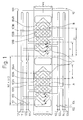
Fig 1 shows a reading head's winding configuration over an eddy-current-type scale for an embodiment having all windings interlaced together. -
Fig 2 shows a winding configuration over a ladder-like conducting scale for an embodiment having separately interlaced drive and sense windings. - A first embodiment of a sensor according to the invention is shown in
Fig 1 . The sensor consists of aflat scale 10 relatively movable along a path x under aflat reading head 100 with fourwindings reading head 100 as seen from above. Thescale 10 has a spatially periodic series of conductingscreens 11, of spatial period T along path x, i.e. along the scale. - Each
winding scale 10, respectively 101A and 101B, 102A and 102B, 103A and 103B, 104A and 104B.Winding elements elements screens 11 is thus shifted by T/2 between one pattern and the other: with reference to each pattern, the screens under pattern A are located in-between the relative positions of the screens under pattern B. - Each winding element facing the scale has its magnetic polarity reversing once per period T along the scale, so it has the same polarity every 2T. Each winding element facing the scale thus has a spatially periodic configuration of
period 2T along the scale. For the sake of clarity and to avoid crowding the drawing, the winding elements shown inFig 1 , which could have any length, only extend over onewinding period 2T, so they have only two contra-rotating loops, i.e. two magnetic polarities each. -
Windings windings Drive windings connectors Sense windings connectors - Starting from
connection 112, drive winding 102 enters itsfirst winding element 102A, turns clockwise in the left loop and counter-clockwise in the right loop, exits and enters its second windingelement 102B, turns clockwise in the left loop and counter-clockwise in the right loop, exits and goes back to itsreturn connection 122. Likewise, drive winding 104 starts fromconnection 114 and goes through itswinding elements winding elements scale 10. - Starting from
connection 111, sense winding 101 enters its first windingelement 101A, turns counter-clockwise in the left loop and clockwise in the right loop, exits and enters its second windingelement 101B, turns clockwise in the left loop and counter-clockwise in the right loop, exits and goes back to itsreturn connection 121. Likewise for sense winding 103, starting atconnection 113 and going through bothwinding elements winding elements scale 10. - Arrows show the winding polarity in the leftmost conductors of
winding elements winding elements - In the embodiment shown in
Fig 1 , the windings' conductors outside patterns A or B are laid out so as to minimize their coupling to other windings, even though this coupling is much weaker than the coupling within patterns A and B. To further diminish unwanted coupling, thereading head 100 may have a conducting screen (not shown), covering as much of the reading head's area as possible and located in a plane parallel to the windings, so that the flat windings lie in-between this screen and the scale. The screen has to be close enough to the flat windings to diminish unwanted coupling, but not too close to impair coupling via the scale. A screen-to-winding plane spacing of about 0.5 T is optimal. This allows a more compact reading head winding configuration. In particular, the separation between both patterns A and B may be reduced significantly. The presence of a screen is also beneficial for suppressing coupling between the windings and the rest of the circuitry (not shown), normally also located on the reading head, but on the side facing away from the scale. If the reading head is a printed circuit with the windings on one side and the rest of the circuitry on the other, a buried layer can be used as a screen. - The embodiment shown in
Fig 1 operates by measuring the amplitude of the signal coupled from each drive winding 102, 104 to each sense winding 101, 103. The presence of the scale's conductingscreens 11 nearby changes the coupling, i.e. the signal's amplitude. The coupling from each drive winding 102, 104 to each sense winding 101, 103 varies thus periodically with a spatial period T as the position of the scale along thereading head 100 changes. A requirement for accuracy is that all couplings vary in a sinusoidal way and within the same range. For this to be the case, there should be the same direct coupling from each drive winding to each sense winding and all couplings via the scale should be uniform. - This is difficult to achieve for direct couplings as well as for couplings via the scale within only one winding element pattern A or B. In winding element pattern A, for example, it is obvious that direct coupling from the rightmost
drive winding element 104A to the leftmostsense winding element 101A is weaker than the other couplings, as they are further apart. This is also true for coupling viascale 10, again because windingelements screens 11 near the middle of pattern A have a significant influence on coupling between these winding elements. This may be improved by making longer patterns, so that the uneven couplings contribution from the ends becomes relatively less important Another improvement is to make the sense winding elements either longer or shorter along the scale than the drive winding elements to reduce if not eliminate coupling from the ends, resulting in more uniform couplings. Still, as direct coupling is preponderant, even a slight disparity in coupling will result in a significant signal distortion within one winding element pattern. - This embodiment provides a simple way to eliminate direct coupling, and to achieve more uniform coupling via the scale. The two winding element patterns A and B are of identical shape and distant enough to avoid cross-coupling from drive windings of one pattern to sense windings of the other. Winding
elements elements elements elements - The direct couplings from each drive winding 102, 104 to each sense winding 101, 103 within each pattern A and B cancel each other out if both patterns are identical.. This is normally the case if reading
head 100 is built in printed circuit technology, with each printed circuit being much smaller than the typical manufacturing size of circuit board panels: process parameters like over- or under-etching, layer-to-layer registration, separation between layers and scaling do not change appreciably within a single printed circuit. Even for marginal process parameters, the effect on all winding elements would still be the same, yielding largely identical winding element patterns. For even higher accuracy, thin film circuits on ceramic substrates or integrated circuits may be used instead of the lower-cost printed circuits. - Uneven coupling via the scale is also compensated in the embodiment shown in
Fig 1 . Assuming the same relative scale feature position in both identical winding elements, the distortion created by each winding element pattern as a function of the position of the reading head along the scale would be the same. In reality, as the relative positions of scale features 11 in each winding element pattern A, B are shifted by half a scale pitch, i.e. T/2, both distortions, or at least their fundamental components of spatial period T, compensate each other. The one parameter most likely to change between both winding element patterns is the local gap to the scale. This will result in a lesser degree of compensation, but again, in this embodiment, uncompensated distortion from direct coupling is worse than uncompensated distortion from coupling via the scale. - The series-connected winding
elements - Having all four winding
elements elements - The
scale 10 of this embodiment consists of an insulating substrate with conductingareas 11, but a homogeneous conducting scale with a three-dimensional pattern, such as a rack, would work as well. It is also possible to replace the scale conductor or conductors by one ore several magnetically permeable elements, which increase rather than decrease the coupling between winding elements nearby. A scale alternating conducting and permeable areas is also feasible. This embodiment is thus optimal in applications requiring a small, simple, rugged scale, with sufficient accuracy. - A second embodiment of a sensor according to the invention is shown in
Fig 2 . The sensor consists of ascale 20 movable along a path x under a reading head (outline not shown) with fourwindings like scale 20 is conducting and has a spatially periodic series ofopenings 22 with a spatial period T along the path x, i.e. along the scale. - Each winding 201, 202, 203, 204 is divided in two separate identical winding elements facing the
scale 20, respectively windingelements 201C and 201D, windingelements elements elements elements elements scale openings 22 to each pattern C or D is thus shifted by T/2: with reference to each pattern, the scale openings under pattern C are located in-between the relative positions of the scale openings under the other pattern D. - Each winding
element scale 20, so it has the same polarity every 2T. Each winding element thus has a spatially periodic configuration ofspatial period 2T along the scale. -
Windings windings windings connectors Sense windings connectors - Starting from
connection 212, drive winding 202 enters its first windingelement 202C, turns counter-clockwise in the first loop it enters, exits and enters its second windingelement 202D, turns clockwise in the first loop it enters, and goes back to itsreturn connection 122. Likewise for drive winding 204, starting atconnection 214 and going through its windingelements 204C, turning counter-clockwise in the first loop entered, and 204D, turning clockwise in the first loop entered. Each drive winding is thus connected to have opposite winding polarities in its two winding elements facing thescale 20. These opposite drive winding element polarities are visualized inFig 2 by four arrows, one under each drive winding element. - Starting from
connection 211, sense winding 201 enters its first windingelement 201C, exits and directly enters its second winding element 201D, exits and goes back to itsreturn connection 221. Likewise for sense winding 203, starting atconnection 213 and going through both windingelements elements 201C, 201D, as well as 203C, 203D is purposefully done so that, unlike the drive windings, each sense winding has the same winding polarity in each winding element facing the scale. These same sense winding element polarities are visualized inFig 2 by four arrows, one under each sense winding element. - Characteristically, this embodiment has separate drive and sense windings. Drive winding
elements element elements sense winding elements elements sense winding elements 201D and 203D in pattern D. Unlike in the embodiment shown inFig 1 , the drive windings and sense windings are not interlaced together inFig 2 . They are separate, extending along the scale and alongside each other. -
Sense winding elements drive winding elements Sense winding elements 201C and 201D, as well as 203C and 203D, are thus directly connected together where winding element patterns C and D meet. Drive windingelements - To further diminish unwanted coupling, a conducting screen (not shown in
Fig 2 ), covering the winding element patterns C and D can be located in a plane parallel to the windings, so that the flat windings lie in-between this screen and the scale. This allows more compact winding element patterns. In particular, the separation required to avoid cross-coupling between the ends of the drive winding elements of one pattern and of the sense winding elements of the other pattern may be reduced. The presence of a screen is also beneficial for suppressing coupling between the windings and the rest of the circuitry (not shown), normally also located on the reading head, on the side facing away from the scale. - In the embodiment shown in
Fig 2 , the interconnections between windingelements connectors drive winding elements drive winding elements - On the reading head's side facing the
scale 20, these interconnections are routed near or within each winding element pattern C or D to keep them as similar as possible electrically. To this end, each drive windingelement Fig 2 on top and just left of the middle fordrive winding elements drive winding elements sense windings 201C and 201 D, on the bottom and slightly to the right forsense windings elements 201C and 201D, respectively 203C and 203D, because these sense winding elements are also directly interconnected with each other where patterns C and D meet. This is of course not the case for the drive winding elements, which have no conductors between them. - Even though these interconnections are routed near these sense windings' extremities, they might still be close enough to their own pattern's drive winding elements to be influenced by them, so that their effect has to be compensated in the other pattern. This is achieved by repeating these interconnections' traces in the other pattern: the interconnection to winding 201 located in pattern C is reproduced as
trace 281 at the same relative position in pattern D and likewise the interconnection to winding 203 located in pattern D is reproduced astrace 273 at the same relative position in pattern C. The direct interconnections betweensense winding elements traces 253 in pattern C for the direct interconnections within pattern D, and in thetraces 263 in pattern D, for the direct interconnections within pattern C. As for the interconnections betweenelements 201C and 20I D, both traces carry opposed currents and are superposed, so there is no need for compensation. In short, all uncompensated current-carrying traces of one pattern are duplicated in the other to get the same coupling conditions in both patterns. - The embodiment shown in
Fig 2 operates by measuring the amplitude of the signal coupled from each drive winding 202, 204 to each sense winding 201, 203. Currents, induced by each drive winding 202, 204 in the part of thescale 20 under them, circulate around theopenings 22 and induce a voltage signal in each sense winding 201, 203: such a conducting ladder-shaped scale thus acts as a coupler between the separate drive and sense windings. The coupling from each drive winding 202, 204 to each sense winding 201, 203, varies thus periodically, with a spatial period T, as the position of the scale'sopenings 22 relative to the windings changes. A requirement for accuracy is that all couplings vary in a sinusoidal way and within the same range. For this to be the case, there should be the same residual direct coupling from each drive winding to each sense winding and all couplings via the scale should be uniform. - Spatial harmonics of the coupling function can be reduced by known techniques, such as a quasi-sinusoidal winding layout, and/or by increasing the gap between the scale and the reading head, as a larger gap smoothes out harmonic distortions from abrupt features like conductor edges. However, a larger gap reduces coupling, so that direct coupling should be reduced accordingly.
- Even though direct coupling is considerably weaker between the separate drive and sense windings of this embodiment than between the interlaced drive and sense windings of the first embodiment, it still exists. Also, distortion for a given amount of direct coupling will be larger, as coupling via the scale for a given gap is reduced by the windings extending only halfway across the width of the scale in this embodiment, rather than fully across in the first embodiment.
- In addition to the requirement for both winding element patterns C and D to be identical, there should be no cross-coupling from drive winding elements in one pattern to sense winding elements in the other. To this effect, drive winding
elements sense winding elements - This embodiment provides a simple way to eliminate direct coupling, and to get more uniform coupling via the scale. Winding
elements elements elements 201C and 201D of sense winding 201, as well as windingelements - The direct couplings from each drive winding 202, 204 to each sense winding 201, 203 within each pattern C and D cancel each other out if both patterns are identical. This is normally the case if the reading head (not shown) is built in printed circuit technology, with each printed circuit being much smaller than the typical manufacturing size of circuit board panels: process parameters like over- or under-etching, layer-to-layer registration, separation between layers and scaling do not change appreciably within a single printed circuit. Even for marginal process parameters, the effect on all winding elements would still be the same, yielding largely identical winding element patterns. For even higher accuracy, thin film circuits on ceramic substrates or integrated circuits may be used instead of lower cost printed circuits.
- The series-connected winding
elements 202C and202D, respectively 204C and 204D, of drive winding 202, respectively 204, carry the same current, thus eliminating the effect of drive current mismatch between both winding patterns C and D. - Uneven coupling via the scale is also compensated in the embodiment shown in
Fig 2 . Assuming the same relative scale feature position in both identical winding elements, the distortion created by each winding element pattern as a function of the position of the reading head along the scale would be the same. In reality, as therelative scale feature 22 positions in each winding element pattern C, D are shifted by half a scale spatial pitch, i.e. T/2, both distortions, or at least their fundamental components of spatial period T, compensate each other. The one parameter most likely to change between both winding element patterns is the local gap to the scale but its effect is limited: even if the local change in gap were as high as T/10, which can be considered extreme in such sensors, the degree of compensation would still cut measuring errors by more than half. With a careful layout, couplings within each pattern C or D are already quite uniform, so that the resulting accuracy would still be fine. However, the main advantage of this embodiment is that it allows a larger gap between reading head and scale, which is again beneficial to accuracy, as a larger gap smoothes out distortions from abrupt features like conductor edges on the scale or on the reading head. - This embodiment is thus eminently suitable for making small reading heads manufactured in printed circuit technology, e.g. for dial indicators and digital gages, with accuracies around one micrometer for scale periods T around 1mm and gaps around 0.1 mm. However, this embodiment is also suitable for less accurate applications with higher gaps and misalignment tolerances between reading head and scale, such as calipers and retro-fit linear encoders: accuracies stay within 10 micrometers for scale periods T around 2 mm and gaps up to 0.5 mm.
- Many other scale patterns are possible, as long as no significant coupling occurs along the length of the scale, as it would lead to coupling between patterns C and D. Instead of the flat conducting ladder-shaped scale with openings, an insulating scale with a series of conducting loops isolated from each other could be used as well. Electrical coupling via current loops around scale loops or openings may be replaced by magnetic coupling through permeable elements, e.g. ferrite bars, arrayed at a pitch T.
- One important advantage of sensors according to the invention is that their better performance is only due to their original winding configuration. Other than that, the number of connections to the drive and sense circuits remains the same and their function can be left uncharged. This allows the use of existing sensor electronics, e.g. as described in
U.S. patent 7,015,617 . These electronics may even be simplified and/or become more accurate, as bias from direct coupling as well as bias from coupling via the scale is eliminated: the periodic coupling signals -ideally sine waves- during a constant speed movement of the scale past the reading head would be without offset, i.e. have an average value of zero. - The scope of the invention is not limited to the embodiments described herein, and many variants are possible. The number of drive and sense windings may be higher than two. There could be a number of pairs of identical winding element patterns, especially in long reading heads. The scale could move on a circumferential path x, as in rotary encoders. The scale and the reading head could be coaxial cylinders, and have an axial or a circumferential path. Although the sensors described above are conceived as incremental sensors measuring over many scale periods T, their good linearity, compact design and high operating frequency (no need for wire wound coils with ferrite cores) makes them quite useful as absolute sensors, i.e. with a measuring range shorter than T, in applications normally using differential transformer (LVDT) or half bridge inductive position sensors or transducers.
Claims (5)
- An inductive position sensor having a relatively movable scale (10, 20) and reading head (100,), the scale (10,20) comprising a spatially periodic series of conducting or permeable features (11,22) of spatial period T, and the reading head (100) comprising drive (102,104,202,204) and sense (101,103,201,203) windings facing the scale (10,20) with a spatially periodic configuration of spatial period 2T along the scale (10,20), wherein the windings (101,...104, 201,...204) facing the scale (10,20) are all divided into at least one pair of identical winding elements (101A, 101B....204C, 204D), each winding element (101A, 101B....204C,204D) having the same relative location within one of at least one pair of distinct winding element patterns (A,B,C,D) having the same shape and a center-to-center distance equal to NT+T/2, N being an integer, each winding's at least one pair of winding elements (101 A, 101 B....204C,204D) being connected so that their polarities are either opposed for each drive winding (102,104,202,204) and equal for each sense winding (101,103,201,203) or equal for each drive winding (102,104,202,204) and opposed for each sense winding (101,103,201,203).
- The sensor according to claim 1, wherein each winding's at least one pair of winding elements (101A, 101B....204C,204D) is connected in series.
- The sensor according to claim 1, wherein all winding elements (101,102,103,104,201,202,203,204) share the same area and are interlaced together within each winding element pattern (A,B,C,D).
- The sensor according to claim 1, wherein the interlaced drive winding elements (102A,102B,104A,104B,202A,202B,204A,204B) are separate from the interlaced sense winding elements (101A,101B,103A,103B,201A,201B,203A,203B) within each winding element pattern (A,B,C,D).
- The sensor according to claim 1, wherein two drive windings (102,104,202,204) are mutually shifted by T/2 along the scale within each winding element pattern and two sense windings (101,103,201,203) are mutually shifted by T/2 along the scale within each winding element pattern.
Applications Claiming Priority (1)
| Application Number | Priority Date | Filing Date | Title |
|---|---|---|---|
| US80775106P | 2006-07-19 | 2006-07-19 |
Publications (3)
| Publication Number | Publication Date |
|---|---|
| EP1881299A2 EP1881299A2 (en) | 2008-01-23 |
| EP1881299A3 EP1881299A3 (en) | 2011-04-20 |
| EP1881299B1 true EP1881299B1 (en) | 2014-05-28 |
Family
ID=38670633
Family Applications (1)
| Application Number | Title | Priority Date | Filing Date |
|---|---|---|---|
| EP07252850.8A Active EP1881299B1 (en) | 2006-07-19 | 2007-07-18 | Inductive position sensor |
Country Status (3)
| Country | Link |
|---|---|
| US (1) | US7652469B2 (en) |
| EP (1) | EP1881299B1 (en) |
| CN (1) | CN101144725B (en) |
Cited By (1)
| Publication number | Priority date | Publication date | Assignee | Title |
|---|---|---|---|---|
| EP4273507A1 (en) | 2022-05-05 | 2023-11-08 | Dr. Johannes Heidenhain GmbH | Scanning element and inductive position measuring device with the same |
Families Citing this family (41)
| Publication number | Priority date | Publication date | Assignee | Title |
|---|---|---|---|---|
| US8222891B2 (en) * | 2009-05-01 | 2012-07-17 | Hewlett-Packard Development Company, L.P. | Compensating for position errors in displacement transducers |
| CN103502777B (en) | 2011-01-07 | 2016-08-17 | 伍德沃德Mpc股份有限公司 | Equipment and method for half-bridge variable differential transformer position sensing system |
| JP5948620B2 (en) * | 2011-09-16 | 2016-07-06 | 株式会社ミツトヨ | Inductive detection type rotary encoder |
| DE102012102855A1 (en) * | 2012-04-02 | 2013-10-02 | Asg Luftfahrttechnik Und Sensorik Gmbh | Method and arrangement for determining the position of a component and sensor |
| JP6297287B2 (en) * | 2013-09-18 | 2018-03-20 | 株式会社ミツトヨ | Rotary encoder and micrometer provided with the same |
| DE102013226200A1 (en) * | 2013-12-17 | 2015-06-18 | Robert Bosch Gmbh | Absolute position measuring device |
| JP6327874B2 (en) * | 2014-02-04 | 2018-05-23 | 株式会社ミツトヨ | Inductive position measuring device |
| CN104266665B (en) * | 2014-09-17 | 2016-09-28 | 上海兰宝传感科技股份有限公司 | Inductance type transducer |
| DE102014221967A1 (en) * | 2014-10-28 | 2016-04-28 | Horst Siedle Gmbh & Co. Kg | Position sensor, position measuring device and operating method for this |
| FR3031589B1 (en) | 2015-01-13 | 2018-11-16 | Hutchinson | INDUCTIVE DISPLACEMENT SENSORS |
| FR3031586B1 (en) | 2015-01-13 | 2017-02-10 | Dymeo | INDUCTIVE DISPLACEMENT SENSORS |
| FR3031587B1 (en) * | 2015-01-13 | 2018-11-16 | Hutchinson | INDUCTIVE DISPLACEMENT SENSORS |
| FR3031588B1 (en) | 2015-01-13 | 2018-11-16 | Hutchinson | INDUCTIVE DISPLACEMENT SENSORS |
| US10527457B2 (en) | 2015-02-27 | 2020-01-07 | Azoteq (Pty) Ltd | Inductance sensing |
| US9772202B1 (en) * | 2016-07-01 | 2017-09-26 | Mitutoyo Corporation | Absolute position encoder combining signals of two widely separated wavelengths |
| US10520335B2 (en) * | 2016-08-24 | 2019-12-31 | Mitutoyo Corporation | Winding configuration for inductive position encoder |
| US10775199B2 (en) * | 2016-08-24 | 2020-09-15 | Mitutoyo Corporation | Winding and scale configuration for inductive position encoder |
| US10612943B2 (en) * | 2016-08-24 | 2020-04-07 | Mitutoyo Corporation | Winding and scale configuration for inductive position encoder |
| EP3299771B1 (en) * | 2016-09-22 | 2020-04-29 | Sagentia Limited | Inductive sensor arrangement |
| JP6877829B2 (en) * | 2017-03-23 | 2021-05-26 | 株式会社ミツトヨ | Electromagnetic induction type displacement detector and measuring instrument using it |
| JP7118627B2 (en) * | 2017-12-01 | 2022-08-16 | 株式会社ミツトヨ | Electromagnetic induction position detector |
| JP2019113542A (en) * | 2017-12-21 | 2019-07-11 | 株式会社ミツトヨ | Winding of electromagnetic induction encoder, and scale configuration |
| DE102019106716A1 (en) * | 2019-03-15 | 2020-09-17 | Balluff Gmbh | Device for the inductive transmission of electrical energy and / or of data and a method for producing such a device |
| CN209605843U (en) * | 2019-04-11 | 2019-11-08 | 郝佳 | Inductive position measurement sensor |
| CN110470323A (en) * | 2019-08-06 | 2019-11-19 | 上海交通大学 | A kind of eddy current type incremental encoder and its working method |
| US11262219B2 (en) * | 2019-08-14 | 2022-03-01 | Hemy8 Sa | Inductive absolute position sensor |
| US11067414B1 (en) | 2020-03-23 | 2021-07-20 | Mitutoyo Corporation | Transmitter and receiver configuration for inductive position encoder |
| US11181395B2 (en) | 2020-03-23 | 2021-11-23 | Mitutoyo Corporation | Transmitter and receiver configuration for inductive position encoder |
| US11169008B2 (en) | 2020-03-23 | 2021-11-09 | Mitutoyo Corporation | Transmitter and receiver configuration for inductive position encoder |
| EP3885711B1 (en) | 2020-03-25 | 2023-03-01 | Melexis Technologies SA | Inductive position sensor |
| DE102020209601A1 (en) * | 2020-07-30 | 2022-02-03 | SUMIDA Components & Modules GmbH | Detection device for a position sensor and detection system with such a detection device |
| JP7471993B2 (en) * | 2020-10-12 | 2024-04-22 | 株式会社ミツトヨ | Electromagnetic Induction Encoder |
| US11713983B2 (en) | 2021-06-30 | 2023-08-01 | Mitutoyo Corporation | Sensing winding configuration for inductive position encoder |
| US20220205814A1 (en) * | 2020-12-31 | 2022-06-30 | Mitutoyo Corporation | Sensing winding configuration for inductive position encoder |
| DE102022117762A1 (en) * | 2022-07-15 | 2024-01-18 | Bourns, Inc. | Inductive sensor for detecting a position |
| US12072213B2 (en) | 2022-08-31 | 2024-08-27 | Mitutoyo Corporation | Inductive position encoder utilizing slanted scale pattern |
| US12072212B2 (en) | 2022-08-31 | 2024-08-27 | Mitutoyo Corporation | Inductive position encoder utilizing transmissive configuration |
| US12385764B2 (en) | 2022-12-30 | 2025-08-12 | Mitutoyo Corporation | Absolute position encoder utilizing single track configuration |
| US12546628B2 (en) | 2023-10-30 | 2026-02-10 | Mitutoyo Corporation | Inductive encoder with shield structures |
| US12553747B2 (en) | 2023-12-20 | 2026-02-17 | Mitutoyo Corporation | Measuring instrument with arc encoder tracks |
| US12553746B2 (en) | 2023-12-20 | 2026-02-17 | Mitutoyo Corporation | Measuring instrument with linear encoder tracks and arc motion |
Family Cites Families (7)
| Publication number | Priority date | Publication date | Assignee | Title |
|---|---|---|---|---|
| SE406642B (en) * | 1977-02-16 | 1979-02-19 | Aga Ab | ELECTROMECHANICAL DOCTOR |
| CH690933A5 (en) * | 1996-01-24 | 2001-02-28 | Hans Ulrich Meyer | An inductive displacement sensor. |
| US5998990A (en) * | 1997-08-25 | 1999-12-07 | Mitutoyo Corporation | Pitch-compensated induced current position transducer |
| US5936399A (en) * | 1997-09-16 | 1999-08-10 | Mitutoyo Corporation | Inductive position transducer having a multi-tap receiver winding |
| EP1164358B1 (en) * | 2000-06-16 | 2005-08-24 | AMO Automatisierung Messtechnik Optik GmbH | Inductive length measuring system |
| DE60332581D1 (en) * | 2002-07-03 | 2010-07-01 | Hans Ulrich Meyer | Inductive position transmitter |
| JP4615955B2 (en) * | 2004-10-12 | 2011-01-19 | 株式会社ミツトヨ | Inductive displacement detector |
-
2007
- 2007-07-13 US US11/777,578 patent/US7652469B2/en active Active
- 2007-07-18 EP EP07252850.8A patent/EP1881299B1/en active Active
- 2007-07-18 CN CN2007101366566A patent/CN101144725B/en not_active Expired - Fee Related
Cited By (3)
| Publication number | Priority date | Publication date | Assignee | Title |
|---|---|---|---|---|
| EP4273507A1 (en) | 2022-05-05 | 2023-11-08 | Dr. Johannes Heidenhain GmbH | Scanning element and inductive position measuring device with the same |
| DE102023201024A1 (en) | 2022-05-05 | 2023-11-09 | Dr. Johannes Heidenhain Gmbh | Scanning element and inductive position measuring device with this scanning element |
| US12287196B2 (en) | 2022-05-05 | 2025-04-29 | Dr. Johannes Heidenhain Gmbh | Scanning element and inductive position measuring device having this scanning element |
Also Published As
| Publication number | Publication date |
|---|---|
| EP1881299A3 (en) | 2011-04-20 |
| CN101144725A (en) | 2008-03-19 |
| CN101144725B (en) | 2012-07-25 |
| EP1881299A2 (en) | 2008-01-23 |
| US7652469B2 (en) | 2010-01-26 |
| US20080018328A1 (en) | 2008-01-24 |
Similar Documents
| Publication | Publication Date | Title |
|---|---|---|
| EP1881299B1 (en) | Inductive position sensor | |
| JP5224838B2 (en) | Electromagnetic induction encoder | |
| US6259249B1 (en) | Induction-type position measuring apparatus | |
| CN110657826B (en) | Scale construction for inductive position encoders | |
| JP4615955B2 (en) | Inductive displacement detector | |
| US5804963A (en) | Inductive displacement sensor with a cursor and a movable coupling scale | |
| CN107560642B (en) | Absolute position encoder combining signals of two widely separated wavelengths | |
| US10323959B2 (en) | Inductive position detector | |
| US20220205814A1 (en) | Sensing winding configuration for inductive position encoder | |
| EP0862727A1 (en) | Position encoder | |
| US20130234730A1 (en) | Sensor of electromagnetic induction type coordinate input device | |
| US11828627B2 (en) | Inductive position sensors | |
| US11713983B2 (en) | Sensing winding configuration for inductive position encoder | |
| US20220205815A1 (en) | Sensing winding configuration for inductive position encoder | |
| CN113614492B (en) | Magnetic linear sensor | |
| HK1114664A (en) | Inductive position sensor | |
| US12385764B2 (en) | Absolute position encoder utilizing single track configuration | |
| CN117091484A (en) | Inductive position measuring device | |
| JP6134964B2 (en) | Inductive displacement detector | |
| US12072213B2 (en) | Inductive position encoder utilizing slanted scale pattern | |
| US12072212B2 (en) | Inductive position encoder utilizing transmissive configuration | |
| US12546628B2 (en) | Inductive encoder with shield structures | |
| JP2002031546A (en) | Magnetic encoder | |
| US20250189348A1 (en) | Inductive position measuring device |
Legal Events
| Date | Code | Title | Description |
|---|---|---|---|
| PUAI | Public reference made under article 153(3) epc to a published international application that has entered the european phase |
Free format text: ORIGINAL CODE: 0009012 |
|
| AK | Designated contracting states |
Kind code of ref document: A2 Designated state(s): AT BE BG CH CY CZ DE DK EE ES FI FR GB GR HU IE IS IT LI LT LU LV MC MT NL PL PT RO SE SI SK TR |
|
| AX | Request for extension of the european patent |
Extension state: AL BA HR MK YU |
|
| REG | Reference to a national code |
Ref country code: HK Ref legal event code: DE Ref document number: 1114664 Country of ref document: HK |
|
| PUAL | Search report despatched |
Free format text: ORIGINAL CODE: 0009013 |
|
| AK | Designated contracting states |
Kind code of ref document: A3 Designated state(s): AT BE BG CH CY CZ DE DK EE ES FI FR GB GR HU IE IS IT LI LT LU LV MC MT NL PL PT RO SE SI SK TR |
|
| AX | Request for extension of the european patent |
Extension state: AL BA HR MK RS |
|
| 17P | Request for examination filed |
Effective date: 20110831 |
|
| AKX | Designation fees paid |
Designated state(s): AT BE BG CH CY CZ DE DK EE ES FI FR GB GR HU IE IS IT LI LT LU LV MC MT NL PL PT RO SE SI SK TR |
|
| GRAP | Despatch of communication of intention to grant a patent |
Free format text: ORIGINAL CODE: EPIDOSNIGR1 |
|
| INTG | Intention to grant announced |
Effective date: 20131106 |
|
| GRAS | Grant fee paid |
Free format text: ORIGINAL CODE: EPIDOSNIGR3 |
|
| GRAA | (expected) grant |
Free format text: ORIGINAL CODE: 0009210 |
|
| AK | Designated contracting states |
Kind code of ref document: B1 Designated state(s): AT BE BG CH CY CZ DE DK EE ES FI FR GB GR HU IE IS IT LI LT LU LV MC MT NL PL PT RO SE SI SK TR |
|
| REG | Reference to a national code |
Ref country code: GB Ref legal event code: FG4D |
|
| REG | Reference to a national code |
Ref country code: CH Ref legal event code: EP |
|
| REG | Reference to a national code |
Ref country code: AT Ref legal event code: REF Ref document number: 670379 Country of ref document: AT Kind code of ref document: T Effective date: 20140615 |
|
| REG | Reference to a national code |
Ref country code: IE Ref legal event code: FG4D |
|
| REG | Reference to a national code |
Ref country code: DE Ref legal event code: R096 Ref document number: 602007036927 Country of ref document: DE Effective date: 20140710 |
|
| REG | Reference to a national code |
Ref country code: AT Ref legal event code: MK05 Ref document number: 670379 Country of ref document: AT Kind code of ref document: T Effective date: 20140528 |
|
| REG | Reference to a national code |
Ref country code: NL Ref legal event code: VDEP Effective date: 20140528 |
|
| REG | Reference to a national code |
Ref country code: LT Ref legal event code: MG4D |
|
| PG25 | Lapsed in a contracting state [announced via postgrant information from national office to epo] |
Ref country code: LT Free format text: LAPSE BECAUSE OF FAILURE TO SUBMIT A TRANSLATION OF THE DESCRIPTION OR TO PAY THE FEE WITHIN THE PRESCRIBED TIME-LIMIT Effective date: 20140528 Ref country code: FI Free format text: LAPSE BECAUSE OF FAILURE TO SUBMIT A TRANSLATION OF THE DESCRIPTION OR TO PAY THE FEE WITHIN THE PRESCRIBED TIME-LIMIT Effective date: 20140528 Ref country code: GR Free format text: LAPSE BECAUSE OF FAILURE TO SUBMIT A TRANSLATION OF THE DESCRIPTION OR TO PAY THE FEE WITHIN THE PRESCRIBED TIME-LIMIT Effective date: 20140829 Ref country code: CY Free format text: LAPSE BECAUSE OF FAILURE TO SUBMIT A TRANSLATION OF THE DESCRIPTION OR TO PAY THE FEE WITHIN THE PRESCRIBED TIME-LIMIT Effective date: 20140528 |
|
| PG25 | Lapsed in a contracting state [announced via postgrant information from national office to epo] |
Ref country code: SE Free format text: LAPSE BECAUSE OF FAILURE TO SUBMIT A TRANSLATION OF THE DESCRIPTION OR TO PAY THE FEE WITHIN THE PRESCRIBED TIME-LIMIT Effective date: 20140528 Ref country code: AT Free format text: LAPSE BECAUSE OF FAILURE TO SUBMIT A TRANSLATION OF THE DESCRIPTION OR TO PAY THE FEE WITHIN THE PRESCRIBED TIME-LIMIT Effective date: 20140528 Ref country code: LV Free format text: LAPSE BECAUSE OF FAILURE TO SUBMIT A TRANSLATION OF THE DESCRIPTION OR TO PAY THE FEE WITHIN THE PRESCRIBED TIME-LIMIT Effective date: 20140528 |
|
| PG25 | Lapsed in a contracting state [announced via postgrant information from national office to epo] |
Ref country code: PT Free format text: LAPSE BECAUSE OF FAILURE TO SUBMIT A TRANSLATION OF THE DESCRIPTION OR TO PAY THE FEE WITHIN THE PRESCRIBED TIME-LIMIT Effective date: 20140929 |
|
| PG25 | Lapsed in a contracting state [announced via postgrant information from national office to epo] |
Ref country code: RO Free format text: LAPSE BECAUSE OF FAILURE TO SUBMIT A TRANSLATION OF THE DESCRIPTION OR TO PAY THE FEE WITHIN THE PRESCRIBED TIME-LIMIT Effective date: 20140528 Ref country code: CZ Free format text: LAPSE BECAUSE OF FAILURE TO SUBMIT A TRANSLATION OF THE DESCRIPTION OR TO PAY THE FEE WITHIN THE PRESCRIBED TIME-LIMIT Effective date: 20140528 Ref country code: DK Free format text: LAPSE BECAUSE OF FAILURE TO SUBMIT A TRANSLATION OF THE DESCRIPTION OR TO PAY THE FEE WITHIN THE PRESCRIBED TIME-LIMIT Effective date: 20140528 Ref country code: BE Free format text: LAPSE BECAUSE OF FAILURE TO SUBMIT A TRANSLATION OF THE DESCRIPTION OR TO PAY THE FEE WITHIN THE PRESCRIBED TIME-LIMIT Effective date: 20140528 Ref country code: EE Free format text: LAPSE BECAUSE OF FAILURE TO SUBMIT A TRANSLATION OF THE DESCRIPTION OR TO PAY THE FEE WITHIN THE PRESCRIBED TIME-LIMIT Effective date: 20140528 Ref country code: ES Free format text: LAPSE BECAUSE OF FAILURE TO SUBMIT A TRANSLATION OF THE DESCRIPTION OR TO PAY THE FEE WITHIN THE PRESCRIBED TIME-LIMIT Effective date: 20140528 Ref country code: SK Free format text: LAPSE BECAUSE OF FAILURE TO SUBMIT A TRANSLATION OF THE DESCRIPTION OR TO PAY THE FEE WITHIN THE PRESCRIBED TIME-LIMIT Effective date: 20140528 |
|
| PG25 | Lapsed in a contracting state [announced via postgrant information from national office to epo] |
Ref country code: PL Free format text: LAPSE BECAUSE OF FAILURE TO SUBMIT A TRANSLATION OF THE DESCRIPTION OR TO PAY THE FEE WITHIN THE PRESCRIBED TIME-LIMIT Effective date: 20140528 Ref country code: LU Free format text: LAPSE BECAUSE OF FAILURE TO SUBMIT A TRANSLATION OF THE DESCRIPTION OR TO PAY THE FEE WITHIN THE PRESCRIBED TIME-LIMIT Effective date: 20140718 Ref country code: NL Free format text: LAPSE BECAUSE OF FAILURE TO SUBMIT A TRANSLATION OF THE DESCRIPTION OR TO PAY THE FEE WITHIN THE PRESCRIBED TIME-LIMIT Effective date: 20140528 |
|
| REG | Reference to a national code |
Ref country code: DE Ref legal event code: R097 Ref document number: 602007036927 Country of ref document: DE |
|
| PLBE | No opposition filed within time limit |
Free format text: ORIGINAL CODE: 0009261 |
|
| STAA | Information on the status of an ep patent application or granted ep patent |
Free format text: STATUS: NO OPPOSITION FILED WITHIN TIME LIMIT |
|
| REG | Reference to a national code |
Ref country code: IE Ref legal event code: MM4A |
|
| REG | Reference to a national code |
Ref country code: FR Ref legal event code: ST Effective date: 20150331 |
|
| PG25 | Lapsed in a contracting state [announced via postgrant information from national office to epo] |
Ref country code: IT Free format text: LAPSE BECAUSE OF FAILURE TO SUBMIT A TRANSLATION OF THE DESCRIPTION OR TO PAY THE FEE WITHIN THE PRESCRIBED TIME-LIMIT Effective date: 20140528 |
|
| 26N | No opposition filed |
Effective date: 20150303 |
|
| PG25 | Lapsed in a contracting state [announced via postgrant information from national office to epo] |
Ref country code: FR Free format text: LAPSE BECAUSE OF NON-PAYMENT OF DUE FEES Effective date: 20140731 |
|
| REG | Reference to a national code |
Ref country code: DE Ref legal event code: R097 Ref document number: 602007036927 Country of ref document: DE Effective date: 20150303 |
|
| PG25 | Lapsed in a contracting state [announced via postgrant information from national office to epo] |
Ref country code: SI Free format text: LAPSE BECAUSE OF FAILURE TO SUBMIT A TRANSLATION OF THE DESCRIPTION OR TO PAY THE FEE WITHIN THE PRESCRIBED TIME-LIMIT Effective date: 20140528 |
|
| PG25 | Lapsed in a contracting state [announced via postgrant information from national office to epo] |
Ref country code: IE Free format text: LAPSE BECAUSE OF NON-PAYMENT OF DUE FEES Effective date: 20140718 |
|
| REG | Reference to a national code |
Ref country code: HK Ref legal event code: WD Ref document number: 1114664 Country of ref document: HK |
|
| PG25 | Lapsed in a contracting state [announced via postgrant information from national office to epo] |
Ref country code: MC Free format text: LAPSE BECAUSE OF FAILURE TO SUBMIT A TRANSLATION OF THE DESCRIPTION OR TO PAY THE FEE WITHIN THE PRESCRIBED TIME-LIMIT Effective date: 20140528 |
|
| PG25 | Lapsed in a contracting state [announced via postgrant information from national office to epo] |
Ref country code: BG Free format text: LAPSE BECAUSE OF FAILURE TO SUBMIT A TRANSLATION OF THE DESCRIPTION OR TO PAY THE FEE WITHIN THE PRESCRIBED TIME-LIMIT Effective date: 20140528 |
|
| PG25 | Lapsed in a contracting state [announced via postgrant information from national office to epo] |
Ref country code: IS Free format text: LAPSE BECAUSE OF FAILURE TO SUBMIT A TRANSLATION OF THE DESCRIPTION OR TO PAY THE FEE WITHIN THE PRESCRIBED TIME-LIMIT Effective date: 20140528 Ref country code: MT Free format text: LAPSE BECAUSE OF FAILURE TO SUBMIT A TRANSLATION OF THE DESCRIPTION OR TO PAY THE FEE WITHIN THE PRESCRIBED TIME-LIMIT Effective date: 20140528 |
|
| PG25 | Lapsed in a contracting state [announced via postgrant information from national office to epo] |
Ref country code: TR Free format text: LAPSE BECAUSE OF FAILURE TO SUBMIT A TRANSLATION OF THE DESCRIPTION OR TO PAY THE FEE WITHIN THE PRESCRIBED TIME-LIMIT Effective date: 20140528 Ref country code: HU Free format text: LAPSE BECAUSE OF FAILURE TO SUBMIT A TRANSLATION OF THE DESCRIPTION OR TO PAY THE FEE WITHIN THE PRESCRIBED TIME-LIMIT; INVALID AB INITIO Effective date: 20070718 |
|
| REG | Reference to a national code |
Ref country code: GB Ref legal event code: 732E Free format text: REGISTERED BETWEEN 20191017 AND 20191023 |
|
| REG | Reference to a national code |
Ref country code: DE Ref legal event code: R082 Ref document number: 602007036927 Country of ref document: DE Representative=s name: POLVERARI, LUCA, DIPL.-ING., LU Ref country code: DE Ref legal event code: R081 Ref document number: 602007036927 Country of ref document: DE Owner name: MELIUS S.A., CH Free format text: FORMER OWNER: ADVANCED SENSOR TECHNOLOGY LTD., HONG KONG, CN |
|
| PGFP | Annual fee paid to national office [announced via postgrant information from national office to epo] |
Ref country code: GB Payment date: 20230629 Year of fee payment: 17 Ref country code: CH Payment date: 20230801 Year of fee payment: 17 |
|
| PGFP | Annual fee paid to national office [announced via postgrant information from national office to epo] |
Ref country code: DE Payment date: 20230703 Year of fee payment: 17 |
|
| REG | Reference to a national code |
Ref country code: DE Ref legal event code: R119 Ref document number: 602007036927 Country of ref document: DE |
|
| REG | Reference to a national code |
Ref country code: CH Ref legal event code: PL |
|
| GBPC | Gb: european patent ceased through non-payment of renewal fee |
Effective date: 20240718 |
|
| PG25 | Lapsed in a contracting state [announced via postgrant information from national office to epo] |
Ref country code: DE Free format text: LAPSE BECAUSE OF NON-PAYMENT OF DUE FEES Effective date: 20250201 |
|
| PG25 | Lapsed in a contracting state [announced via postgrant information from national office to epo] |
Ref country code: CH Free format text: LAPSE BECAUSE OF NON-PAYMENT OF DUE FEES Effective date: 20240731 |
|
| PG25 | Lapsed in a contracting state [announced via postgrant information from national office to epo] |
Ref country code: GB Free format text: LAPSE BECAUSE OF NON-PAYMENT OF DUE FEES Effective date: 20240718 |