EP1882553A2 - Outil électrique doté d'une lumière - Google Patents
Outil électrique doté d'une lumière Download PDFInfo
- Publication number
- EP1882553A2 EP1882553A2 EP07014207A EP07014207A EP1882553A2 EP 1882553 A2 EP1882553 A2 EP 1882553A2 EP 07014207 A EP07014207 A EP 07014207A EP 07014207 A EP07014207 A EP 07014207A EP 1882553 A2 EP1882553 A2 EP 1882553A2
- Authority
- EP
- European Patent Office
- Prior art keywords
- light
- hammer case
- unit
- power tool
- tool
- Prior art date
- Legal status (The legal status is an assumption and is not a legal conclusion. Google has not performed a legal analysis and makes no representation as to the accuracy of the status listed.)
- Granted
Links
Images


Classifications
-
- B—PERFORMING OPERATIONS; TRANSPORTING
- B25—HAND TOOLS; PORTABLE POWER-DRIVEN TOOLS; MANIPULATORS
- B25B—TOOLS OR BENCH DEVICES NOT OTHERWISE PROVIDED FOR, FOR FASTENING, CONNECTING, DISENGAGING OR HOLDING
- B25B23/00—Details of, or accessories for, spanners, wrenches, screwdrivers
- B25B23/18—Devices for illuminating the head of the screw or the nut
-
- B—PERFORMING OPERATIONS; TRANSPORTING
- B25—HAND TOOLS; PORTABLE POWER-DRIVEN TOOLS; MANIPULATORS
- B25F—COMBINATION OR MULTI-PURPOSE TOOLS NOT OTHERWISE PROVIDED FOR; DETAILS OR COMPONENTS OF PORTABLE POWER-DRIVEN TOOLS NOT PARTICULARLY RELATED TO THE OPERATIONS PERFORMED AND NOT OTHERWISE PROVIDED FOR
- B25F5/00—Details or components of portable power-driven tools not particularly related to the operations performed and not otherwise provided for
- B25F5/02—Construction of casings, bodies or handles
- B25F5/021—Construction of casings, bodies or handles with guiding devices
-
- Y—GENERAL TAGGING OF NEW TECHNOLOGICAL DEVELOPMENTS; GENERAL TAGGING OF CROSS-SECTIONAL TECHNOLOGIES SPANNING OVER SEVERAL SECTIONS OF THE IPC; TECHNICAL SUBJECTS COVERED BY FORMER USPC CROSS-REFERENCE ART COLLECTIONS [XRACs] AND DIGESTS
- Y10—TECHNICAL SUBJECTS COVERED BY FORMER USPC
- Y10T—TECHNICAL SUBJECTS COVERED BY FORMER US CLASSIFICATION
- Y10T408/00—Cutting by use of rotating axially moving tool
- Y10T408/21—Cutting by use of rotating axially moving tool with signal, indicator, illuminator or optical means
Definitions
- the present invention relates to a power tool, and particularly to a power tool having a light for irradiating an end tool and a workpiece.
- U.S. Patent No. 7,185,998 (corresponding to Japanese Patent Application Publication No. 2003-211374 ) discloses a power tool including a housing accommodating a motor, a holding part for holding an end tool, and a hammer case for accommodating an impact mechanism that transmits driving force of the motor to the holding part.
- the power tool is also provided with a light-emitting diode (LED) or other light source that illuminates the front of the power tool so that work can be performed in dark locations safely and without difficulties.
- LED light-emitting diode
- the light source of the power tool including the LED or other light is mounted as a unit or assembly (hereinafter referred to as a "light unit") on the front of the housing or the front of the hammer case.
- the light unit could receive an unanticipated impact due to the power tool colliding with a workpiece or being dropped.
- a power tool including a main housing, a motor, a hammer case, an end-tool holding part, a driving-force transmitting mechanism, a light-unit mounting part, a light unit, and a cover.
- the motor is accommodated in the main housing and is configured to generate a driving force.
- the hammer case has an outer peripheral surface.
- the end-tool holding part is configured to hold an end tool.
- the driving-force transmitting mechanism is accommodated in the hammer case.
- the driving-force transmitting mechanism is configured to transmit the driving force to the end-tool holding part.
- the light-unit mounting part is formed integrally with the hammer case.
- the light unit is mounted to the light-unit mounting part.
- the cover covers the outer peripheral surface of the hammer case and accommodates the light-unit mounting part and the light unit.
- the present invention provides a power tool including a main housing, a motor, a hammer case, an end-tool holding part, a driving-force transmitting mechanism, a handle housing, a trigger switch, a light-unit mounting part, and a light unit.
- the main housing extends in a first direction.
- the motor is accommodated in the main housing and is configured to generate a driving force.
- the hammer case is provided adjacent to the main housing and has an outer peripheral surface.
- the end-tool holding part is configured to hold an end tool.
- the driving-force transmitting mechanism is accommodated in the hammer case.
- the driving-force transmitting mechanism is configured to transmit the driving force to the end-tool holding part.
- the handle housing is connected to the main housing.
- the handle housing extends in a second direction that intersects the first direction.
- the trigger switch is provided at the handle housing and adjacent to the hammer case.
- the trigger switch is configured to control power supply to the motor.
- the light-unit mounting part is provided at the outer peripheral surface of the hammer case and is formed integrally with the hammer case.
- the light-unit mounting part is formed with an insertion hole and with a slit.
- the light unit is accommodated in the insertion hole.
- the light unit has an engaging part that engages the slit.
- the present invention provides a power tool including a main:housing, a motor, a hammer case, an end-tool holding part, a driving-force transmitting mechanism, a handle housing, a trigger switch, a guide sleeve, a rib, and a light unit.
- the main housing extends in a first direction.
- the motor is accommodated in the main housing and is configured to generate a driving force.
- the hammer case is provided adjacent to the main housing and has an outer peripheral surface.
- the end-tool holding part is configured to hold an end tool, wherein the main housing, the hammer case, and the end-tool holding part are arranged in the first direction, such that the end-tool holding part is positioned at a front side and that the main housing is positioned at a rear side.
- the driving-force transmitting mechanism is accommodated in the hammer case.
- the driving-force transmitting mechanism is configured to transmit the driving force to the end-tool holding part.
- the handle housing is connected to the main housing.
- the handle housing extends in a second direction that intersects the first direction.
- the trigger switch is provided at the handle housing and adjacent to the hammer case.
- the trigger switch is configured to control power supply to the motor.
- the guide sleeve is provided at a front end of the hammer case.
- the rib protrudes from the outer peripheral surface of the hammer case and is provided between the trigger switch and the guide sleeve with respect to the first direction.
- the light unit includes a lighting element that irradiates light, and a holder member that holds the lighting element and that is mounted to the rib.
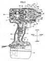
- the impact driver 1 has a housing 2 and a hammer case 3 constituting an outer frame of the impact driver 1.
- the housing 2 includes a main body 2A substantially cylindrical in shape and extending in the front-to-rear direction, and a handle part 2B joined with the main body 2A to form a substantially T-shape in a side view.
- the hammer case 3 is substantially cylindrical in shape and formed of an aluminum alloy.
- the hammer case 3 is provided at the front end of the housing 2.
- a guide sleeve 3A is provided on the front end of the hammer case 3.
- a protector 21 is provided for covering the outer periphery of the hammer case 3 and a light unit 15 described later.
- the protector 21 is formed of a lightweight material such as an elastomer.
- the protector 21 includes a peripheral part 21P having a substantially cylindrical shape and a box-like pouch member 21A (light-unit accommodating part) that is integrally formed with the peripheral part 21P and that protrudes downward (radially outwardly) for accommodating the light unit 15.
- the protector 21 is fixed to the hammer case 3 by a stopper 22 formed of an elastic material such as rubber.
- a motor 4 serving as the drive source of the impact driver 1 is accommodated in the main body 2A of the housing 2.
- the motor 4 has an output shaft 4a for outputting a rotational force.
- the hammer case 3 accommodates a planetary gear mechanism 5 serving as a speed reduction mechanism for reducing the rotational speed of the motor 4, and an impact mechanism (not shown) for converting rotations of the motor 4 reduced by the planetary gear mechanism 5 to a rotational impact force and transmitting this force to an end tool (not shown).
- the impact mechanism includes a spindle 16, a hammer 17, balls 18, a spring 19, and an anvil 20 (end-tool holding part). The impact mechanism will be described in greater detail later.
- a trigger 6 is provided at the upper section of the handle part 2B for switching power supply to the motor 4.
- a switch 7 connected to the trigger 6 is accommodated in the upper section of the handle part 2B.
- a switching lever 8, a battery receiving part 9, a circuit board 10, and lead wires 11 and 12 are accommodated in the lower section of the handle part 2B.
- a rechargeable battery 13 is detachably mounted on the bottom end of the handle part 2B. Power is supplied from the battery 13 to the motor 4 through the two lead wires 11, the switch 7, and a field-effect transistor (FET) 14.
- the light unit 15 is attached to the lower front end of the hammer case 3. Power is supplied from the battery 13 to the light unit 15 via the circuit board 10, and the two lead wires 12.
- the motor 4 is activated when the user switches on the trigger 6. At this time, rotation of the output shaft 4a of the motor 4 is transmitted to the spindle 16 after being reduced by the planetary gear mechanism 5 and drives the spindle 16 to rotate at a prescribed speed.
- the spindle 16 is linked with the hammer 17 by a cam mechanism.
- the cam mechanism is configured of V-shaped spindle cam grooves 16a formed in the outer surfaces of the spindle 16, a V-shaped hammer cam groove 17a formed in the inner surface of the hammer 17, and the balls 18 engaged in the spindle cam grooves 16a and the hammer cam groove 17a.
- the spring 19 constantly urges the hammer 17 in a frontward direction.
- a gap is formed between the hammer 17 and the anvil 20 by the engagement of the balls 18 and the spindle cam grooves 16a and the engagement of the balls 18 and the hammer cam grooves 17a.
- the hammer 17 has a pair of protrusions 17P which protrude from a surface 17S of the hammer 17 at symmetrical positions about a rotational axis RA.
- the anvil 20 has a pair of arms 20A which extend radially outwardly at symmetrical positions about the rotational axis RA.
- An end tool such as a bit (not shown) is detachably mounted to the anvil 20.
- the cam mechanism transmits the rotation of the spindle 16 to the hammer 17.
- the protrusions 17P of the hammer 17 engage with the arms 20A of the anvil 20 before the hammer 17 completes a half rotation, thereby rotating the anvil 20.
- the reaction force generated at the moment of this engagement produces relative rotation between the hammer 17 and the anvil 20
- the hammer 17 begins to retract along the spindle cam grooves 16a toward the motor 4, while compressing the spring 19.
- the rotational impact force is intermittently and repeatedly transmitted from the end tool to the screw, driving the screw into the wood or other workpiece (not shown).
- the light unit 15 is mounted at a position forward of the trigger 6 disposed below the hammer case 3 and rearward of the guide sleeve 3A provided on the front end of the hammer case 3.
- a rib 3B (light-unit mounting part, protruding part) protrudes from the lower front end of the hammer case 3 at a position forward of the trigger 6 and rearward of the guide sleeve 3A.
- a screw hole 3b-1 is formed to penetrate the rib 3B in a left-right direction.
- the light unit 15 shown in Fig. 5 includes a base plate 23, a chip LED 24 (lighting element), a holder member 25, and two lead wires 12.
- the base plate 23 has a thin rectangular plate shape.
- the LED 24 is attached to the base plate 23.
- the two lead wires 12 extend horizontally from upper and lower positions on a rear surface of the base plate 23. Note that the base plate 23, chip LED 24, and two lead wires 12 constitute a lighting-element unit.
- the holder member 25 is integrally molded of a transparent resin, such as an acrylic.
- the holder member 25 has a block-shaped main body 25A in which are formed a rectangular accommodating space 25a open in the top of the main body 25A, and a slit-shaped fitting groove 25b elongated in the left-right direction and narrow in the front-rear direction.
- Two leg parts 25B and 25C protrude integrally from the surface of the main body 25A on right and left sides thereof.
- a circular hole 25c is formed to penetrate the leg part 25B in the left-right direction.
- a holding part 25d is integrally provided on the end of the leg part 25C so that the leg part 25C and the holding part 25d form an L-shape in a plan view.
- Two fitting grooves 25d-1 extending horizontally in the front-rear direction are formed in a side endface of the holding part 25d at upper and lower positions thereof.
- the light unit 15 is mounted on the lower front end of the hammer case 3 as described blow.
- the base plate 23 (attached with the chip LED 24 and the lead wires 12) is inserted from above into the slit-shaped fitting groove 25b of the holder member 25, such that the LED 24 is accommodated in the accommodating space 25a (see also Fig. 9).
- the holder member 25 holding the base plate 23 and the LED 24 is mounted on the rib 3B. More specifically, the rib 3B is fitted between the two leg parts 25B and 25C of the holder member 25, and a screw 26 is inserted through the hole 25c formed in the leg part 25B and screwed into the screw hole 3b-1 formed in the rib 3B.
- the impact driver 1 can be used to perform operations in dark areas, such as under flooring or in an attic.
- a switch (not shown) to supply power from the battery 13 to the light unit 15 via the circuit board 10 and lead wires 12, light irradiated from the LED 24 illuminates the end tool and workpiece (not shown), thereby enabling the user to work efficiently and without difficulty.
- the holder member 25 is used to mount the light unit 15 on the rib 3B.
- the rib 3B protrudes from the lower front end of the hammer case 3 at a position forward of the trigger 6 and rearward of the guide sleeve 3A disposed on the front end of the hammer case 3.
- the light unit 15 is positioned closer to the end tool and workpiece, which are the illumination targets, enabling a small LED 24 with a low capacity to illuminate the target with sufficient brightness.
- the light unit 15 can be made smaller and more compact.
- the small LED 24 is easy to mount in the holder member 25 by simply inserting the base plate 23 into the slit-shaped fitting groove 25b from the top of the holder member 25.
- the holder member 25 can be easily and reliably mounted on the rib 3B of the hammer case 3 using the screw 26.
- the base plate 23 is prevented from floating up from the holder member 25 by fitting the lead wires 12 into the two upper and lower fitting grooves 25d-1. Hence, a screw or other fastener is not needed to fix the base plate 23 to the holder member 25, thereby reducing the number of required parts and reducing the manufacturing cost.
- FIG. 10 A power tool according to a second embodiment of the invention will be described while referring to Figs. 10 through 12, wherein like parts and components are designated by the same reference numerals to avoid duplicating description.
- the holder member 25 retaining the base plate 23 and LED 24 is attached to the hammer case 3 by fitting the holder member 25 onto the rib 3B of the hammer case 3.
- the holder member 25 can be easily mounted on the rib 3B in one step, as shown in Fig. 11. In other words, a faster such as screw is not used in the present embodiment.
- the protector 21 shown in Fig. 10 covers and retains the holder member 25.
- a lower rib-shaped guide 21B is integrally formed in the pouch member 21A, protruding upward from the inside lower surface of the pouch member 21A.
- an upper rib-shaped guide 21C is integrally formed in the pouch member 21A, protruding downward from the inside upper surface of the pouch member 21A.
- the holder member 25 mounted on the rib 3B of the hammer case 3 is fitted into the pouch member 21A of the protector 21 along the guides 21B and 21C. Accordingly, the pouch member 21A covers and holds the holder member 25, with the lower surface of the holder member 25 received by and supported on the lower guide 21B and with the upper surface of the holder member 25 received by and supported on the upper guide 21C.
- the holder member 25 can be easily fitted over and mounted on the rib 3B of the hammer case 3 in one step and can be reliably retained by the protector 21. Hence, the holder member 25 is reliably prevented from falling off the rib 3B.
- FIG. 13 through 19 A power tool according to a third embodiment of the invention will be described while referring to Figs. 13 through 19, wherein like parts and components are designated by the same reference numerals to avoid duplicating description.
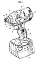
- Fig. 13 shows an impact driver 51 according to the third embodiment.
- the impact driver 51 includes a main housing 52 substantially cylindrical in shape and extending in a front-rear direction along a rotational axis X of a DC motor 54; a handle housing 53 joined with the main housing 52 and extending in a vertical Y-direction orthogonal to the extending direction of the main housing 52 (X-direction) or a Z-direction at a certain angle ⁇ from the Y-direction; and a hammer case 64 that is bell-shaped and accommodates an impact mechanism.
- the main housing 52 is coupled to the hammer case 64 by screws (not shown).
- a battery pack housing section (not shown) is provided in a lower end portion of the handle housing 53, and a battery pack (not shown) is mounted in the battery pack housing section.
- the speed reduction mechanism 56 includes a pinion 56a which serves as an output shaft of the motor 54, and a planetary gear 56b engaged with the pinion 56a.
- the hammer case 64 accommodates an impact mechanism 57, and an anvil 58 that receives an impact force from the impact mechanism 57 and rotates.
- the impact mechanism 57 includes a spindle 57a for transmitting the rotational force from the speed reduction mechanism 56, a coil spring 57b provided around an outer surface of the spindle 57a, and a hammer 57c that generates an impact force by the action of the coil spring 57b.
- An end-tool holding part 66 is provided on a front end of the anvil 58 for detachably mounting a drill bit (not shown) or other end tool. The drill bit or desired end tool can be inserted into the end-tool holding part 66 and clamped therein.
- a protective cover 59 includes a peripheral part 59A covering an outer peripheral surface of the hammer case 64, and a protruding part 59B protruding downward (radially outwardly) from the peripheral part 59A for accommodating the light-unit accommodating part 64a and the light unit 60.
- the protective cover 59 is formed of an elastic material such as rubber.
- a front cap 65 fits onto a front end of the hammer case 64 for preventing the protective cover 59 from coming unseated.
- a trigger switch 55 is provided on the handle housing 53 positioned below the hammer case 64 for controlling the supply of power from the battery pack (not shown) to the motor 54.
- the motor 54 is driven to rotate.
- the rotational force of the motor 54 is transmitted via the speed reduction mechanism 56 and impact mechanism 57 provided in the main housing 52 and the anvil 58 provided in the hammer case 64. Since the end tool is mounted in the end-tool holding part 66, the force is transmitted to the end tool as a rotational impact force for driving a screw or other fastener into a workpiece (not shown).
- the light-unit accommodating part 64a (light-unit mounting part) is integrally provided as a member of the hammer case 64 at a position on a lower peripheral surface of the hammer case 64.
- a light unit (light assembly) 60 is mounted in the light-unit accommodating part 64a.
- the light unit 60 includes a lighting element 62 configured of an LED, for example.
- the optical axis of the lighting element 62 is adjusted so that the lighting element 62 can irradiate light in front of and to left and right sides of the end-tool holding part 66.
- the lighting element 62 is accommodated at a position as near as possible to the rotational axis X.
- the lighting element 62 irradiates light in front of and to the left and right sides of the end-tool holding part 66 in synchronization with an ON operation of the trigger switch 55, enabling the impact driver 51 to be used in a dark work area.
- the light unit 60 includes a light cover 61 described later (see Figs. 16A through 16C), the lighting element 62 configured of an LED or the like, and a lead wire 63 electrically connecting the lighting element 62 to a power supply circuit provided in the handle housing 53.
- the light-unit accommodating part 64a accommodating the light unit 60 is integrally formed with the hammer case 64 at a position on a lower peripheral surface of the hammer case 64.
- an insertion hole (nest) 64b (concave part) for accommodating the light unit 60 is formed in the light-unit accommodating part 64a.
- the insertion hole 64b has an inner peripheral surface 64i.
- a slit 64c is formed in the light-unit accommodating part 64a in the front-rear direction. The slit 64c extends over the entire protruding part of the light-unit accommodating part 64a along an insertion direction in which the light unit 60 is inserted in the insertion hole 64b.
- the light cover 61 constituting part of the light unit 60 has an engaging part (protruding part) 61c.
- the light cover 61 also has an outer peripheral surface 61s.
- the engaging part 61c slidingly engaged with the slit 64c simultaneously.
- the outer peripheral surface 61s of the light cover 61 slides on the inner peripheral surface 64i of the insertion hole 64b.
- An engaging part (hook part) 61f is provided on a rear end of the engaging part 61c.
- the engaging part 61f engages with a rear wall portion 64f of the light-unit accommodating part 64a, as illustrated in Fig. 19, thus fixing the light cover 61 in the light-unit accommodating part 64a.
- the light cover 61 is formed by joining a first half-split cover 61a (shown in Fig. 17A) and a second half-split cover 61b (shown in Fig. 17B). Note that the hatched regions in Figs. 17A and 17B show joining surfaces between the half-split covers 61a and 61b.
- the lighting element 62 is first arranged in a light insertion hole (recessed part) 61e formed in the second half-split cover 61b, with the lead wire 63 drawn out through a lead wire hole 61d.
- the first half-split cover 61a is placed over the second half-split cover 61b, forming the light cover 61 that can be inserted into the insertion hole 64b of the light-unit accommodating part 64a.
- the optical axis of the lighting element 62 i.e. a center axis B of the light insertion hole 61e, is adjusted to a prescribed angle ⁇ a relative to a center axis A of the light cover 61.
- the light unit 60 configured of the lighting element 62, the lead wire 63, and the light cover 61 is inserted into the insertion hole 64b formed in the light-unit accommodating part 64a according to the following procedure.
- the lead wire 63 of the light unit 60 is inserted through the slit 64c in the light-unit accommodating part 64a, and pulled out from the rear of the light-unit accommodating part 64a.
- the main body of the light unit 60 is inserted into the insertion hole 64b.
- the engaging part 61c of the light unit 60 slides in the slit 64c.
- the engaging part 61f engages with the rear wall portion 64f of the light-unit accommodating part 64a, thereby serving as a first retaining member.
- the slit 64c and the rear wall portion 64f fix the position of the engaging part 61c, the light unit 60 can be accommodated at a prescribed positional relationship with the light-unit accommodating part 64a.
- the protective cover 59 formed of rubber or another elastic material is fitted over the hammer case 64.
- the protruding part 59B of the protective cover 59 is formed with a window (hole) at a diameter D2 which is smaller than a diameter D1 of the insertion hole 64b.
- the protective cover 59 can enhance the reliability of holding the lighting element 62 in the insertion hole 64b when fitted over the light-unit accommodating part 64a of the hammer case 64.
- the front cap 65 is attached to the front end part of the hammer case 64, thereby preventing the protective cover 59 from coming unseated. Accordingly, the protective cover 59 and the front cap 65 serve as a second retaining member for the light unit 60.
- the light unit 60 can be accurately positioned when inserted into the insertion hole 64b, thereby obtaining a predetermined light-irradiating angle. Further, the engaging part 61f of the light cover 61 engages with the light-unit accommodating part 64a of the hammer case 64, as shown in Fig. 19, preventing the light unit 60 from coming out, to the front, from the insertion hole 64b.
- the lighting element 62 can be disposed in the light-unit accommodating part 64a of the hammer case 64 and the light unit 60 can be positioned near the rotational axis X and the front end of the impact driver 51, the illuminating range of the lighting element 62 can be increased. That is, the lighting element 62 can illuminate a broad region in order to support different lengths of screws driven by the end tool and different lengths of the end tool, while eliminating shadows formed by the body of the impact driver 51.
- the light cover 61 of an elastic material can reduce the effects of vibrations generated in the body of the impact driver 51 and heat generated in the hammer case 64.
- the protective cover 59 is configured of an elastic material that can absorb unanticipated impacts, such as when the impact driver 51 collides with a workpiece, thereby preventing damage to the light-unit accommodating part 64a or the light unit 60.
- the light unit 60 since the light unit 60 according to the present embodiment is fixed by the light-unit accommodating part 64a and the engaging part 61c and, hence, requires no screws, the light unit 60 can easily be removed from the hammer case 64 by disengaging the engaging part 61f from the light-unit accommodating part 64a, thereby facilitating replacement of the lighting element 62.
- plugs and sockets as the method of connecting wiring for the lighting element 62, connection and mounting of the electric parts can also be simplified.
- the present invention is applied to a cordless impact driver equipped with a rechargeable battery, but the present invention may also be applied to an impact driver having an electric cord. Further, it should be apparent that the present invention is not limited to impact drivers, but may be applied to a wide range of power tools, such as a nail gun.
Landscapes
- Engineering & Computer Science (AREA)
- Mechanical Engineering (AREA)
- Details Of Spanners, Wrenches, And Screw Drivers And Accessories (AREA)
Applications Claiming Priority (2)
| Application Number | Priority Date | Filing Date | Title |
|---|---|---|---|
| JP2006202746A JP4936213B2 (ja) | 2006-07-26 | 2006-07-26 | 電動工具 |
| JP2006243170A JP4923883B2 (ja) | 2006-09-07 | 2006-09-07 | 電動工具 |
Publications (3)
| Publication Number | Publication Date |
|---|---|
| EP1882553A2 true EP1882553A2 (fr) | 2008-01-30 |
| EP1882553A3 EP1882553A3 (fr) | 2009-04-15 |
| EP1882553B1 EP1882553B1 (fr) | 2011-09-21 |
Family
ID=38621958
Family Applications (1)
| Application Number | Title | Priority Date | Filing Date |
|---|---|---|---|
| EP07014207A Active EP1882553B1 (fr) | 2006-07-26 | 2007-07-19 | Outil électrique doté d'une lumière |
Country Status (6)
| Country | Link |
|---|---|
| US (1) | US7677752B2 (fr) |
| EP (1) | EP1882553B1 (fr) |
| AU (1) | AU2007203468B2 (fr) |
| BR (1) | BRPI0704508B1 (fr) |
| CA (1) | CA2594441C (fr) |
| RU (1) | RU2355562C1 (fr) |
Cited By (4)
| Publication number | Priority date | Publication date | Assignee | Title |
|---|---|---|---|---|
| GB2459190A (en) * | 2008-04-18 | 2009-10-21 | Bosch Gmbh Robert | Hand-held power tool with protector part |
| FR2930187A1 (fr) * | 2008-04-18 | 2009-10-23 | Bosch Gmbh Robert | Machine outil a main |
| EP2199024A1 (fr) * | 2008-12-16 | 2010-06-23 | Robert Bosch Gmbh | Outil motorisé portable |
| RU2497657C2 (ru) * | 2009-03-02 | 2013-11-10 | Макита Корпорейшн | Электрический инструмент |
Families Citing this family (49)
| Publication number | Priority date | Publication date | Assignee | Title |
|---|---|---|---|---|
| US7404696B2 (en) * | 2005-02-18 | 2008-07-29 | Black & Decker Inc. | Drill driver with chuck-mounted drill accessories |
| US8421375B2 (en) | 2007-06-25 | 2013-04-16 | Ingersoll-Rand Company | Amplification circuit and heat sink used with a light emitting apparatus having varying voltages |
| WO2009049367A1 (fr) * | 2007-10-19 | 2009-04-23 | Whitehot Solutions Pty Ltd | Outil manuel à multiples mandrins de serrage |
| DE102007061741A1 (de) * | 2007-12-20 | 2009-06-25 | Robert Bosch Gmbh | Werkzeugmaschine mit einer Arbeitsfeldbeleuchtung |
| CA2717860C (fr) | 2008-03-07 | 2016-11-08 | Milwaukee Electric Tool Corporation | Boitier de batterie pour une utilisation avec un outil motorise et un outil de detection non motorise |
| US20090321101A1 (en) * | 2008-06-26 | 2009-12-31 | Makita Corporation | Power tool |
| EP2147753B1 (fr) * | 2008-07-25 | 2017-01-18 | AEG Electric Tools GmbH | Outil électrique doté d'une commutation de transmission |
| US8328381B2 (en) | 2009-02-25 | 2012-12-11 | Black & Decker Inc. | Light for a power tool and method of illuminating a workpiece |
| US8317350B2 (en) | 2009-02-25 | 2012-11-27 | Black & Decker Inc. | Power tool with a light for illuminating a workpiece |
| US20110058356A1 (en) | 2009-02-25 | 2011-03-10 | Black & Decker Inc. | Power tool with light emitting assembly |
| JP5479023B2 (ja) * | 2009-10-20 | 2014-04-23 | 株式会社マキタ | 充電式電動工具 |
| US12059780B2 (en) | 2010-09-30 | 2024-08-13 | Black & Decker Inc. | Lighted power tool |
| US9328915B2 (en) | 2010-09-30 | 2016-05-03 | Black & Decker Inc. | Lighted power tool |
| US9028088B2 (en) | 2010-09-30 | 2015-05-12 | Black & Decker Inc. | Lighted power tool |
| US9776315B2 (en) | 2011-11-11 | 2017-10-03 | Black & Decker Inc. | Power tool having interchangeable tool heads with an independent accessory switch |
| US9242355B2 (en) | 2012-04-17 | 2016-01-26 | Black & Decker Inc. | Illuminated power tool |
| US9796073B2 (en) * | 2012-08-27 | 2017-10-24 | Ingersoll-Rand Company | Housing for power tool |
| US20140196922A1 (en) * | 2013-01-17 | 2014-07-17 | Black & Decker Inc. | Electric power tool with improved visibility in darkness |
| USD938095S1 (en) | 2013-04-01 | 2021-12-07 | Pathy Medical, Llc | Lighting device |
| US9851060B2 (en) | 2013-04-01 | 2017-12-26 | Vinod V. Pathy | Lighting device for attachment to a tool |
| JP6085225B2 (ja) | 2013-06-27 | 2017-02-22 | 株式会社マキタ | ネジ締め電動工具 |
| USD725981S1 (en) | 2013-10-29 | 2015-04-07 | Black & Decker Inc. | Screwdriver with nosepiece |
| US20150151424A1 (en) | 2013-10-29 | 2015-06-04 | Black & Decker Inc. | Power tool with ergonomic handgrip |
| CN104779109B (zh) * | 2014-01-13 | 2018-08-28 | 博世电动工具(中国)有限公司 | 电动工具的开关机构以及电动工具 |
| US10717179B2 (en) * | 2014-07-28 | 2020-07-21 | Black & Decker Inc. | Sound damping for power tools |
| US9889508B2 (en) * | 2014-08-28 | 2018-02-13 | Hougen Manufacturing, Inc. | Magnetically mountable portable drill assembly |
| USD774570S1 (en) | 2014-08-28 | 2016-12-20 | Hougen Manufacturing, Inc. | Magnetic base with illuminator for magnetically mountable portable drill |
| US10486291B2 (en) | 2014-11-12 | 2019-11-26 | Ingersoll-Rand Company | Integral tool housing heat sink for light emitting diode apparatus |
| WO2016196979A1 (fr) | 2015-06-05 | 2016-12-08 | Ingersoll-Rand Company | Outils de percussion avec fonctionnalités d'alignement de couronne dentée |
| WO2016196984A1 (fr) | 2015-06-05 | 2016-12-08 | Ingersoll-Rand Company | Machines portatives à moteur à modes de fonctionnement sélectionnables par l'utilisateur |
| WO2016196899A1 (fr) | 2015-06-05 | 2016-12-08 | Ingersoll-Rand Company | Boîtiers d'outil électrique |
| WO2016196891A1 (fr) | 2015-06-05 | 2016-12-08 | Ingersoll-Rand Company | Interfaces utilisateur de machine-outil électrique |
| EP3302880B1 (fr) * | 2015-06-05 | 2026-01-14 | Ingersoll-Rand Industrial U.S., Inc. | Systèmes d'éclairages pour outils électriques |
| US10615670B2 (en) | 2015-06-05 | 2020-04-07 | Ingersoll-Rand Industrial U.S., Inc. | Power tool user interfaces |
| WO2021173431A1 (fr) | 2020-02-24 | 2021-09-02 | Milwaukee Electric Tool Corporation | Outil à percussion |
| CN212653400U (zh) | 2020-06-12 | 2021-03-05 | 米沃奇电动工具公司 | 具有照明组件的摆动电动工具 |
| CN212553690U (zh) | 2020-06-12 | 2021-02-19 | 米沃奇电动工具公司 | 摆动电动工具 |
| JP7523965B2 (ja) * | 2020-06-29 | 2024-07-29 | 株式会社マキタ | 打ち込み工具 |
| US12233523B2 (en) | 2020-12-07 | 2025-02-25 | Black & Decker Inc. | Power tool with multiple modes of operation and ergonomic handgrip |
| CA3156645A1 (fr) * | 2021-04-28 | 2022-10-28 | Gripguard Inc. | Dispositif de protection contre les chutes d'outil electrique |
| US11835217B2 (en) | 2021-05-06 | 2023-12-05 | Black & Decker Inc. | Light emitting assembly for a power tool |
| CN113664256A (zh) * | 2021-07-29 | 2021-11-19 | 张慧敏 | 一种钻孔角度自动调节的钻孔设备 |
| WO2023086237A1 (fr) | 2021-11-12 | 2023-05-19 | Milwaukee Electric Tool Corporation | Système d'éclairage sans ombre pour outil électrique portatif |
| JP2023079884A (ja) | 2021-11-29 | 2023-06-08 | 株式会社マキタ | インパクトドライバ |
| US20250042004A1 (en) * | 2021-12-01 | 2025-02-06 | Milwaukee Electric Tool Corporation | Rotary impact tool |
| US12569971B2 (en) | 2023-01-27 | 2026-03-10 | Black & Decker Inc. | Angled tool accessory holder |
| US12544883B2 (en) | 2023-03-13 | 2026-02-10 | Milwaukee Electric Tool Corporation | Power tool with lighting assembly and wire passageway |
| US12429213B2 (en) | 2023-05-16 | 2025-09-30 | Milwaukee Electric Tool Corporation | Power tool utilizing optical fibers to output light |
| US12533784B2 (en) | 2023-05-30 | 2026-01-27 | Milwaukee Electric Tool Corporation | Shadowless lighting design for a power tool |
Family Cites Families (15)
| Publication number | Priority date | Publication date | Assignee | Title |
|---|---|---|---|---|
| US2310166A (en) * | 1941-01-24 | 1943-02-02 | Singer Mfg Co | Lighting device for portable electric tools |
| US2525588A (en) * | 1946-12-12 | 1950-10-10 | Leroy F Cameron | Illuminated electric drill and the like |
| IT223418Z2 (it) * | 1990-02-07 | 1995-07-19 | Spiranyl S A R 1 S R L | Dispositivo per l'avvitamento e lo svitamento di viti,bulloni e dadi. |
| US5797670A (en) * | 1996-08-23 | 1998-08-25 | American Industrial Design Co., Inc. | Portable power tool light, accessory mounting belt, and method of using same |
| FR2768355B1 (fr) * | 1997-09-18 | 1999-12-03 | Daniel Jean Marie Toujas | Perceuse/visseuse/devisseuse d'angle sans fil a source d'eclairage integree et a double possibilite d'alimentation electrique |
| IT1313279B1 (it) | 1999-07-30 | 2002-07-17 | Makita S P A | Dispositivo di illuminazione per macchine utensili elettriche emacchina utensile comprendente tale dispositivo. |
| JP2002301669A (ja) | 2001-04-05 | 2002-10-15 | Makita Corp | 電動工具 |
| JP4169184B2 (ja) * | 2001-11-15 | 2008-10-22 | 株式会社マキタ | 打撃工具 |
| JP2003211374A (ja) | 2002-01-21 | 2003-07-29 | Hitachi Koki Co Ltd | 電動工具 |
| JP4567294B2 (ja) * | 2003-02-07 | 2010-10-20 | 株式会社マキタ | 電動工具 |
| US20050194166A1 (en) * | 2003-06-10 | 2005-09-08 | Goodti Industrial Co., Ltd. | High torque electromotive tool |
| DE10330180A1 (de) * | 2003-07-04 | 2005-01-27 | Robert Bosch Gmbh | Handwerkzeugmaschine |
| JP4254408B2 (ja) * | 2003-07-25 | 2009-04-15 | パナソニック電工株式会社 | ライト付き電動工具 |
| JP4122300B2 (ja) * | 2004-01-13 | 2008-07-23 | 株式会社マキタ | 打撃工具 |
| DE102004051913A1 (de) * | 2004-08-09 | 2006-02-23 | Robert Bosch Gmbh | Akkuschrauber |
-
2007
- 2007-07-19 EP EP07014207A patent/EP1882553B1/fr active Active
- 2007-07-23 BR BRPI0704508-5A patent/BRPI0704508B1/pt not_active IP Right Cessation
- 2007-07-23 CA CA2594441A patent/CA2594441C/fr not_active Expired - Fee Related
- 2007-07-25 AU AU2007203468A patent/AU2007203468B2/en not_active Ceased
- 2007-07-25 US US11/782,691 patent/US7677752B2/en active Active
- 2007-07-26 RU RU2007128620/02A patent/RU2355562C1/ru not_active IP Right Cessation
Cited By (6)
| Publication number | Priority date | Publication date | Assignee | Title |
|---|---|---|---|---|
| GB2459190A (en) * | 2008-04-18 | 2009-10-21 | Bosch Gmbh Robert | Hand-held power tool with protector part |
| FR2930187A1 (fr) * | 2008-04-18 | 2009-10-23 | Bosch Gmbh Robert | Machine outil a main |
| GB2459190B (en) * | 2008-04-18 | 2013-01-30 | Bosch Gmbh Robert | Hand-held power tool |
| EP2199024A1 (fr) * | 2008-12-16 | 2010-06-23 | Robert Bosch Gmbh | Outil motorisé portable |
| US8496366B2 (en) | 2008-12-16 | 2013-07-30 | Robert Bosch Gmbh | Hand-held power tool |
| RU2497657C2 (ru) * | 2009-03-02 | 2013-11-10 | Макита Корпорейшн | Электрический инструмент |
Also Published As
| Publication number | Publication date |
|---|---|
| AU2007203468B2 (en) | 2009-06-04 |
| US7677752B2 (en) | 2010-03-16 |
| RU2355562C1 (ru) | 2009-05-20 |
| CA2594441A1 (fr) | 2008-01-26 |
| CA2594441C (fr) | 2010-08-17 |
| EP1882553A3 (fr) | 2009-04-15 |
| RU2007128620A (ru) | 2009-02-10 |
| EP1882553B1 (fr) | 2011-09-21 |
| BRPI0704508B1 (pt) | 2019-04-16 |
| US20080025017A1 (en) | 2008-01-31 |
| BRPI0704508A (pt) | 2008-04-08 |
| AU2007203468A1 (en) | 2008-02-14 |
Similar Documents
| Publication | Publication Date | Title |
|---|---|---|
| EP1882553B1 (fr) | Outil électrique doté d'une lumière | |
| CN101112757B (zh) | 配备灯的电动工具 | |
| US8382308B2 (en) | Power tool having a work field lighting system | |
| JP7754645B2 (ja) | 電動工具 | |
| CN114290296B (zh) | 手持式工具机 | |
| JP7523965B2 (ja) | 打ち込み工具 | |
| US12605808B2 (en) | Power tool | |
| JP2009214239A (ja) | 電動工具 | |
| JP6068264B2 (ja) | 集塵装置 | |
| CN112074378A (zh) | 手持式工具机 | |
| JP4923883B2 (ja) | 電動工具 | |
| JP2004174667A (ja) | 電動工具用チャック及び電動工具 | |
| JP2009095902A (ja) | 打撃工具 | |
| US12337446B2 (en) | Impact tool | |
| WO2021033357A1 (fr) | Dispositif d'éclairage pour appareil portatif, et appareil portatif | |
| JP7676183B2 (ja) | インパクト工具 | |
| JP5192674B2 (ja) | 電動工具 | |
| JP5664642B2 (ja) | 電動工具 | |
| CN115431227A (zh) | 动力工具 | |
| JP2024157934A (ja) | 電動工具 | |
| CN104889943A (zh) | 动力工具 |
Legal Events
| Date | Code | Title | Description |
|---|---|---|---|
| PUAI | Public reference made under article 153(3) epc to a published international application that has entered the european phase |
Free format text: ORIGINAL CODE: 0009012 |
|
| AK | Designated contracting states |
Kind code of ref document: A2 Designated state(s): AT BE BG CH CY CZ DE DK EE ES FI FR GB GR HU IE IS IT LI LT LU LV MC MT NL PL PT RO SE SI SK TR |
|
| AX | Request for extension of the european patent |
Extension state: AL BA HR MK YU |
|
| PUAL | Search report despatched |
Free format text: ORIGINAL CODE: 0009013 |
|
| AK | Designated contracting states |
Kind code of ref document: A3 Designated state(s): AT BE BG CH CY CZ DE DK EE ES FI FR GB GR HU IE IS IT LI LT LU LV MC MT NL PL PT RO SE SI SK TR |
|
| AX | Request for extension of the european patent |
Extension state: AL BA HR MK RS |
|
| 17P | Request for examination filed |
Effective date: 20091009 |
|
| AKX | Designation fees paid |
Designated state(s): DE FR GB |
|
| GRAP | Despatch of communication of intention to grant a patent |
Free format text: ORIGINAL CODE: EPIDOSNIGR1 |
|
| GRAS | Grant fee paid |
Free format text: ORIGINAL CODE: EPIDOSNIGR3 |
|
| RTI1 | Title (correction) |
Free format text: POWER TOOL EQUIPPED WITH LIGHT |
|
| GRAA | (expected) grant |
Free format text: ORIGINAL CODE: 0009210 |
|
| AK | Designated contracting states |
Kind code of ref document: B1 Designated state(s): DE FR GB |
|
| REG | Reference to a national code |
Ref country code: GB Ref legal event code: FG4D |
|
| REG | Reference to a national code |
Ref country code: DE Ref legal event code: R096 Ref document number: 602007017302 Country of ref document: DE Effective date: 20111117 |
|
| PLBE | No opposition filed within time limit |
Free format text: ORIGINAL CODE: 0009261 |
|
| STAA | Information on the status of an ep patent application or granted ep patent |
Free format text: STATUS: NO OPPOSITION FILED WITHIN TIME LIMIT |
|
| 26N | No opposition filed |
Effective date: 20120622 |
|
| REG | Reference to a national code |
Ref country code: DE Ref legal event code: R097 Ref document number: 602007017302 Country of ref document: DE Effective date: 20120622 |
|
| REG | Reference to a national code |
Ref country code: FR Ref legal event code: PLFP Year of fee payment: 10 |
|
| REG | Reference to a national code |
Ref country code: FR Ref legal event code: PLFP Year of fee payment: 11 |
|
| REG | Reference to a national code |
Ref country code: DE Ref legal event code: R082 Ref document number: 602007017302 Country of ref document: DE Representative=s name: STREHL SCHUEBEL-HOPF & PARTNER MBB PATENTANWAE, DE Ref country code: DE Ref legal event code: R081 Ref document number: 602007017302 Country of ref document: DE Owner name: KOKI HOLDINGS CO., LTD., JP Free format text: FORMER OWNER: HITACHI KOKI CO., LTD., TOKIO/TOKYO, JP |
|
| REG | Reference to a national code |
Ref country code: FR Ref legal event code: PLFP Year of fee payment: 12 |
|
| PGFP | Annual fee paid to national office [announced via postgrant information from national office to epo] |
Ref country code: GB Payment date: 20240722 Year of fee payment: 18 |
|
| PGFP | Annual fee paid to national office [announced via postgrant information from national office to epo] |
Ref country code: FR Payment date: 20240729 Year of fee payment: 18 |
|
| PGFP | Annual fee paid to national office [announced via postgrant information from national office to epo] |
Ref country code: DE Payment date: 20250722 Year of fee payment: 19 |
|
| GBPC | Gb: european patent ceased through non-payment of renewal fee |
Effective date: 20250719 |
|
| PG25 | Lapsed in a contracting state [announced via postgrant information from national office to epo] |
Ref country code: GB Free format text: LAPSE BECAUSE OF NON-PAYMENT OF DUE FEES Effective date: 20250719 |
|
| PG25 | Lapsed in a contracting state [announced via postgrant information from national office to epo] |
Ref country code: FR Free format text: LAPSE BECAUSE OF NON-PAYMENT OF DUE FEES Effective date: 20250731 |