EP1887532B1 - System und Verfahren zur Detektion von Miniatursicherheitskennzeichen - Google Patents
System und Verfahren zur Detektion von Miniatursicherheitskennzeichen Download PDFInfo
- Publication number
- EP1887532B1 EP1887532B1 EP07114059.4A EP07114059A EP1887532B1 EP 1887532 B1 EP1887532 B1 EP 1887532B1 EP 07114059 A EP07114059 A EP 07114059A EP 1887532 B1 EP1887532 B1 EP 1887532B1
- Authority
- EP
- European Patent Office
- Prior art keywords
- points
- cluster
- anchor
- marks
- template
- Prior art date
- Legal status (The legal status is an assumption and is not a legal conclusion. Google has not performed a legal analysis and makes no representation as to the accuracy of the status listed.)
- Not-in-force
Links
- 238000000034 method Methods 0.000 title claims description 39
- 238000001514 detection method Methods 0.000 title claims description 28
- 239000011159 matrix material Substances 0.000 claims description 20
- 238000005070 sampling Methods 0.000 claims description 11
- 238000012360 testing method Methods 0.000 claims description 5
- 238000012795 verification Methods 0.000 claims description 5
- 230000001419 dependent effect Effects 0.000 claims description 3
- 238000009499 grossing Methods 0.000 claims description 2
- 238000007639 printing Methods 0.000 description 5
- 238000012986 modification Methods 0.000 description 4
- 230000004048 modification Effects 0.000 description 4
- 230000002265 prevention Effects 0.000 description 4
- 230000008569 process Effects 0.000 description 3
- 230000009471 action Effects 0.000 description 2
- 238000013459 approach Methods 0.000 description 2
- 230000008901 benefit Effects 0.000 description 2
- 230000003139 buffering effect Effects 0.000 description 2
- 239000003086 colorant Substances 0.000 description 2
- 238000010586 diagram Methods 0.000 description 2
- 238000005516 engineering process Methods 0.000 description 2
- 238000000605 extraction Methods 0.000 description 2
- 230000006870 function Effects 0.000 description 2
- 238000009877 rendering Methods 0.000 description 2
- 238000012549 training Methods 0.000 description 2
- 230000009286 beneficial effect Effects 0.000 description 1
- 230000005540 biological transmission Effects 0.000 description 1
- 238000004891 communication Methods 0.000 description 1
- 238000004590 computer program Methods 0.000 description 1
- 238000013527 convolutional neural network Methods 0.000 description 1
- 238000003384 imaging method Methods 0.000 description 1
- 238000003780 insertion Methods 0.000 description 1
- 230000037431 insertion Effects 0.000 description 1
- 239000000463 material Substances 0.000 description 1
- 230000003287 optical effect Effects 0.000 description 1
- 238000012545 processing Methods 0.000 description 1
- 238000000926 separation method Methods 0.000 description 1
Images


Classifications
-
- G—PHYSICS
- G07—CHECKING-DEVICES
- G07D—HANDLING OF COINS OR VALUABLE PAPERS, e.g. TESTING, SORTING BY DENOMINATIONS, COUNTING, DISPENSING, CHANGING OR DEPOSITING
- G07D7/00—Testing specially adapted to determine the identity or genuineness of valuable papers or for segregating those which are unacceptable, e.g. banknotes that are alien to a currency
- G07D7/06—Testing specially adapted to determine the identity or genuineness of valuable papers or for segregating those which are unacceptable, e.g. banknotes that are alien to a currency using wave or particle radiation
- G07D7/12—Visible light, infrared or ultraviolet radiation
-
- G—PHYSICS
- G07—CHECKING-DEVICES
- G07D—HANDLING OF COINS OR VALUABLE PAPERS, e.g. TESTING, SORTING BY DENOMINATIONS, COUNTING, DISPENSING, CHANGING OR DEPOSITING
- G07D7/00—Testing specially adapted to determine the identity or genuineness of valuable papers or for segregating those which are unacceptable, e.g. banknotes that are alien to a currency
- G07D7/003—Testing specially adapted to determine the identity or genuineness of valuable papers or for segregating those which are unacceptable, e.g. banknotes that are alien to a currency using security elements
Definitions
- This disclosure relates generally to methods and systems for counterfeit prevention, and more particularly to a system and method for automatically detecting miniature security marks in documents or images.
- the simplest method involves flipping the lowest-order bit of chosen pixels in a gray scale or color image. This works well only if the image will not be subject to any human or noisy modification.
- a more robust watermark can be embedded in an image in the same way that a watermark is added to paper. Such techniques may superimpose a watermark symbol over an area of the picture and then add some fixed intensity value for the watermark to the varied pixel values of the image. The resulting watermark may be visible or invisible depending upon the value (large or small, respectively) of the watermark intensity.
- Spatial watermarking can also be applied using color separation.
- the watermark appears in only one of the color bands. This type of watermark is visibly subtle and difficult to detect under normal viewing conditions.
- the colors of the image are separated for printing or xerography, the watermark appears immediately. This renders the document useless to the printer unless the watermark can be removed from the color band.
- This approach is used commercially for journalists to inspect digital pictures from a photo-stockhouse before buying un-watermarked versions.
- MSMs Miniature Security Marks
- the MSMs can be embedded in documents or images to be protected. When the documents or images are scanned, processed, and sent to a printer, the MSM detectors in the imaging system may recognize the embedded MSM marks and defeat the counterfeit attempts.
- the MSM has an advantage over existing technologies, such as watermarking, in that it requires only very simple and inexpensive detectors. Consequently, the MSM may be applied to many devices in a cost-effective manner.
- U.S. Patent Application Publication No. 2006/0115110 describes a system for authenticating security documents in which a document includes a first surface having a first and second set of print structures and a second surface.
- the sets of print structures cooperate to obscure the location on the first surface of the second set of print structures.
- the second set of print structures is arranged on the first surface so to provide a reflection pattern, such as a diffraction grating.
- the second set of print structures is preferably provided with metallic ink on the first surface.
- U.S. Patent No. 6,694,042 enables a variety of document management functions by printing documents with machine readable indicia, such as steganographic digital watermarks or barcodes.
- the indicia can be added as part of the printing process (after document data has been output by an originating application program), such as by printer driver software, by a Postscript engine in a printer, etc.
- the indicia can encode data about the document, or can encode an identifier that references a database record containing such data.
- a suitable optical input device such as a webcam
- an electronic version of the document can be recalled for editing, or other responsive action can be taken.
- U.S. Patent No. 7,002,704 teaches a system for rendering an electronic image representation associated with a software application program.
- the system includes a PC-based host processor programmed to execute the software application program, a temporary storage device associated with the host processor, and a printer interfaced to the host processor.
- a printer driver routine is operative on the host processor and determines whether the electronic image representation is of a counterfeit document by examining at least a portion of the electronic image representation when stored in the temporary storage device during the course of printing the electronic image representation at the printer.
- EP 0 917 113 A2 describes seal detection system and method.
- a currency detection method that detects seals on currency in order to prevent printing and defeat counterfeiting. Seal patterns are detected.
- the detector has the ability to identify whether an image contains one or several pre-selected seal patterns.
- the detection is rotational and shift invariant - a suspect mark can be in any orientation and at any location within a tested image.
- a detector is trained off-line with distinctive marks resulting in templates which are generated and recorded for each of said distinctive; sample images bearing suspect marks are received by said detector and the location and orientation of said suspect marks are identified; said templates are rotated and shifted for alignment of said templates to said suspect marks; said templates and said suspects marks are compared to determine whether there is a match.;
- a microprocessor is programmed to become familiarized with a plurality of distinctive marks through training and to analyze and detect seals within tested documents.
- a memory stores the marks as templates.
- a scanner may be used with the system during training and detection to capture marks and tested images bearing marks for use by the system. The resulting output can be used by controlled systems, such as copiers and scanners, to suspend further action on documents where counterfeiting is suspected.
- FIG. 1 is a functional block diagram of one exemplary embodiment of a system for detection of MSMs in documents and/or images;
- FIG. 2 is a flowchart outlining one exemplary embodiment of the method for detecting MSMs in documents and/or images
- FIG. 3 is a flow chart outlining one exemplary embodiment of group configuration checking.
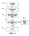
- FIG. 4 is a flow chart outlining one exemplary embodiment of a method for matching MSM location points in a group with a template configuration.
- MSMs are differentiated from image content and noise in three aspects: MSMs have significant color differences from the image background, each MSM has a pre-determined shape (circle, square, etc.), and MSMs form certain predetermined patterns.
- MSMs For hierarchical MSMs, the patterns can be decomposed into two layers, a bottom layer with a fixed pattern, and a top layer, which specifies the relative positions and orientations of the bottom layer groups.
- MSM will include both hierarchical and non-hierarchical MSMs.
- the system includes an analyzer and a database that stores mark shape information.
- the detection method includes sub-sampling to prepare a coarse image that can be analyzed efficiently. Using the coarse image, maximum/minimum points are detected using a mark feature, such as the color difference between the marks and the background. A group of candidate marks is isolated and evaluated to determine if they form predetermined patterns. The shape of the marks is then verified.
- Various computing environments may incorporate capabilities for supporting a network on which the system and method for detecting MSMs may reside.
- the following discussion is intended to provide a brief, general description of suitable computing environments in which the method and system may be implemented.
- program modules include routines, programs, objects, components, data structures, etc., that perform particular tasks or implement particular abstract data types.
- program modules include routines, programs, objects, components, data structures, etc., that perform particular tasks or implement particular abstract data types.
- the method and system may be practiced with other computer system configurations, including hand-held devices, multi-processor systems, microprocessor-based or programmable consumer electronics, networked PCs, minicomputers, mainframe computers, and the like.
- a security mark as used herein can be any mark (e.g., depression, impression, raised, overlay, etc.) that is applied to a recipient such as an image, a graphic, a picture, a document, a body of text, etc.
- the security mark can contain information that can be detected, extracted and/or interpreted. Such information can be employed to prevent counterfeiting by verifying that the information contained within the security mark is accurate, thereby verifying the authenticity of the recipient upon which the security mark is applied.
- a security mark has an MSM configuration that includes at least one data mark and at least two anchor marks.
- the MSMs may have different colors and shapes.
- the anchor marks within an MSM configuration have at least one attribute (e.g., size, shape, color, etc.) that is different than the at least one data marks. In this manner, no anchor mark can have all the same attributes of any data mark.
- the location, size and/or shape of the one or more data marks can determine the information contained therein.
- an MSM configuration can contain nineteen data marks and two anchor marks.
- the size, shape and color of both the anchor marks and data marks can be known such that the anchor marks can be distinguished from each other.
- the location of the anchor marks in each MSM configuration can be known to each other and known relative to the one or more data marks.
- information can be stored and extracted from a MSM configuration utilizing one or more algorithms associated therewith.
- the one or more algorithms can utilize at least one of mark location, size, shape and color to store and/or extract data from a MSM configuration.
- Anchor marks can be employed to limit the amount of computational overhead employed in the detection and extraction of an MSM configuration. For example, greater detection requirements can be necessary since the rotation, shift and/or scaling of an image (and MSM configuration applied therein) is unknown. As a result, the computational complexity may grow exponentially as the number of marks increases. Generally, anchor marks can allow rapid determination of the location of an MSM configuration. In particular, the location of the at least one data mark relative to the anchor marks within the MSM configuration can be quickly determined. In this manner, excessive computation overhead can be mitigated. Moreover, MSM configurations can create smaller footprints than the digital watermarks, which can lower buffering storage requirements. This is particularly beneficial when a greater number of data and/or anchor marks are employed. In one aspect, a detector can first identify the anchor marks, and then use them to determine location, orientation and scaling parameters. These parameters can be applied to locate the data marks at a linear computational complexity.
- the system includes MSM detection module 130, algorithm store 110, and interpretation module 160. These devices are coupled together via data communication links which may be any type of link that permits the transmission of data, such as direct serial connections.
- the detection module 130 can employ one or more algorithms to extract information contained within one or more security marks. Algorithms can contain one or more formulae, equations, methods, etc. to interpret data represented by a particular security mark.
- the security mark is an MSM configuration wherein data is represented by two or more anchor marks and one or more data marks.
- the detection module 130 includes analyzer 140, which analyzes the location of the data marks relative to each other and/or relative to two or more anchor marks, as well as the location of the anchor marks relative to each other to insure that an MSM configuration exists in a particular location. The size, shape, color, orientation, etc. of the marks can also be analyzed to extract information contained within the one or more MSM configurations.
- Detection module 130 also includes database 150, which contains mark shape information (circle, square, etc.) for each MSM.
- the algorithm store 110 can be employed to store, organize, edit, view, and retrieve one or more algorithms for subsequent use.
- the detection module 130 can retrieve one or more algorithms from the algorithm store 110 to determine the information contained within an MSM configuration.
- the detection module 130 can determine the appropriate algorithm, methodology, etc. to extract information from one or more security marks and transmit such information to the algorithm store 110 for subsequent use.
- the interpretation module 160 can determine the meaning related to data extracted from one or more security marks by the detection module 130. Such a determination can be made based on one or more conditions such as the location of the security mark, the recipient upon which the security mark is applied, the location of the system, one or more predetermined conditions, etc. In addition, a look up table, a database, etc. can be employed by the interpretation module 160 to determine the meaning of data extracted from a security mark.
- the security mark is related to the recipient upon which the security mark is applied. For instance, a data string "5jrwm38f6ho" may have a different meaning when applied to a one hundred dollar bill versus a one hundred euro bill.
- the particular methods performed for detecting MSMs comprise steps which are described below with reference to a series of flow charts.
- the flow charts illustrate an embodiment in which the methods constitute computer programs made up of computer-executable instructions. Describing the methods by reference to a flowchart enables one skilled in the art to develop software programs including such instructions to carry out the methods on computing systems.
- the language used to write such programs can be procedural, such as Fortran, or object based, such as C++.
- One skilled in the art will realize that variations or combinations of these steps can be made without departing from the scope of the disclosure herein.
- FIG. 2 a flowchart illustrates an example embodiment of the method for detecting MSMs in documents and/or images.
- sub-sampling is performed to generate a reduced-resolution version of the original image, which can be more efficiently analyzed.
- the sub-sampling and associated low-pass pre-smoothing reduce an MSM mark to a blurred spot that loses its shape information.
- the sub-sampling factor is selected such that the resulting mark size is reduced to about one pixel in the reduced-resolution image.
- Sub-sampling processes are well-known in the art and can be found, for example, in text books such as " Digital Picture Processing" by A. Rosenfeld and A. C. Kak, Academic Press, 1982 .
- Maximum/minimum points detection is performed at 220, which divides the reduced-resolution image into disjoint windows, with each window having a plurality of pixels. In each window the maximum and/or minimum points are detected as the potential MSM locations. Depending on the MSM mark color, different color spaces may be operated on, and either maximum or minimum points identified. For example, if the marks are darker than the background in the L* component of the L*a*b* (the Commission Internationale de L'eclairage color standard) color space, the minimum value pixels in L* may be checked.
- the window size is chosen to be as large as possible with the constraint that no two marks will appear in the same window.
- the system performs maximum/minimum points grouping, which includes grouping the points detected at 220 into clusters according to their location distances. Two points whose distance is smaller than a pre-determined threshold are considered to be in the same group and are candidates for the clusters.
- Group configuration checking is performed at 240 to match the groups obtained at 230 with a pre-defined template configuration, discussed more fully with reference to Figure 3 below.
- the system performs shape verification in the original resolution rather than in the reduced resolution version. From each point (in the reduced-resolution image) in the groups that satisfy group configuration checking, the corresponding position in the original image is found. For marks with rotation invariant shapes, such as circles, a template matching can be applied. Otherwise, the template (or the mark) must be first rotated, according to the group orientation.
- the flow charts illustrate example embodiments for group configuration checking, which matches the groups obtained through maximum/minimum points grouping with a pre-defined template configuration for each group.
- the system determines at 310 if the number of points in the group is equal to the number of points in the template. If this is not the case, the group is discarded at 320.
- a determination is made at 330 as to whether anchor points have been assigned. If no anchor points have been assigned, as is usually the case with hierarchical MSM, for which the number of points contained in a group is relatively small, the distances between points in the group are matched with the distances between points in the template at 340, discussed more fully with respect to Figure 4 below.
- E ⁇ 1 Min i , j ⁇ ⁇ m , n > m D i ⁇ j - T m ⁇ n
- E1 is smaller than a pre-determined threshold. If the threshold has not been exceeded, the group will be further tested at 450. Otherwise, it is discarded at 460.
- an additional test is required to determine if the groups form certain pre-defined relationships, with the operations dependent on the defined relationship. For example, if an MSM requires three identical pattern groups with two of them in the same orientation and the third group rotated 90 degrees, the orientations of the groups would be evaluated to determine if any of them contain a ⁇ , ⁇ , ⁇ +90° pattern.
- anchor points have been defined, which is usual for a large group
- the anchor points in the group are matched with the anchor points in the template.
- the anchor points typically differ in color from the rest points (non-anchor points) in the group, rendering them easily identifiable.
- the anchor points in the group are then matched with the anchor points in the template at 350, applying the method of Figure 4 , except that it is applied only to anchor points, rather than to all points in the group.
- the distances between the anchor points and the rest of the points in the group are calculated at 360.
- K and M are the number of anchor and non-anchor points, respectively, and D(m,i) is the distance between points m and i.
- Matrix D1 is matched to matrix T1, which records the anchor and non-anchor distances for the template, at 370.
- E2 is smaller than a pre-determined threshold at 380. If the error is less than the threshold, the group will be further tested at 390. Otherwise, it is discarded at 320.
- code as used herein, or “program” as used herein, is any plurality of binary values or any executable, interpreted or compiled code which can be used by a computer or execution device to perform a task. This code or program can be written in any one of several known computer languages.
- a "computer”, as used herein, can mean any device which stores, processes, routes, manipulates, or performs like operation on data. It is to be understood, therefore, that this disclosure is not limited to the particular forms illustrated and that it is intended in the appended claims to embrace all alternatives, modifications, and variations which do not depart from the spirit and scope of the embodiments described herein.
Landscapes
- Physics & Mathematics (AREA)
- General Physics & Mathematics (AREA)
- Health & Medical Sciences (AREA)
- General Health & Medical Sciences (AREA)
- Toxicology (AREA)
- Engineering & Computer Science (AREA)
- Computer Security & Cryptography (AREA)
- Editing Of Facsimile Originals (AREA)
- Facsimile Image Signal Circuits (AREA)
- Image Processing (AREA)
Claims (10)
- Verfahren zum Erfassen von Miniatur-Sicherheitskennzeichenkonfigurationen in Dokumenten und Bildern, wobei die Miniatur-Sicherheitskennzeichen Datenkennzeichen oder eine Kombination aus Datenkennzeichen und Ankerkennzeichen enthalten, wobei das Verfahren umfasst:Unterabtasten (210) eines empfangenen Bilds, wobei das empfangene Bild eine digitale Repräsentation wenigstens eines möglichen Empfängers der Miniatur-Sicherheitskennzeichen umfasst, wobei das Unterabtasten ein Bild mit einer reduzierten Auflösung des empfangenen Bilds erzeugt,Durchführen einer Maximum-/Minimumpunkte-Erfassung (220),Gruppieren (230) der Maximum-/Minimumpunkte in wenigstens ein Cluster in Übereinstimmung mit Positionsdistanzen zwischen den Maximum-/Minimumpunkten,Prüfen (240), ob das durch das Gruppieren der Maximum-/Minimumpunkte erhaltene wenigstens eine Cluster einer vordefinierten Schablonenkonfiguration entspricht, undDurchführen einer Formverifizierung (250) in dem empfangenen Bild, wobei das Durchführen der Formverifizierung das Finden von jedem Punkt in dem wenigstens einen Cluster einer entsprechenden Position in dem empfangenen Bild umfasst,dadurch gekennzeichnet, dassdas Durchführen einer Maximum-/Minimumpunkte-Erfassung umfasst:Teilen des Bilds mit einer reduzierten Auflösung in getrennte Fenster, wobei jedes dieser Fenster eine Vielzahl von Bildpunkten enthält, undErfassen der Maximum- und/oder Minimumpunkte in jedem Fenster, wobei die Maximum- und/oder Minimumpunkte mögliche Positionen von Miniatur-Sicherheitskennzeichen sind.
- Verfahren nach Anspruch 1, wobei das Unterabtasten (210) weiterhin das Reduzieren der Größe des Miniatur-Sicherheitskennzeichens auf ungefähr einen Bildpunkt in dem Bild mit der reduzierten Auflösung umfasst.
- Verfahren nach Anspruch 1, wobei das Unterabtasten (210) weiterhin ein Tiefpass-Vorglätten umfasst, um zu veranlassen, dass ein Miniatur-Sicherheitskennzeichen Forminformationen verliert.
- Verfahren nach Anspruch 1, wobei die Fenster eine Größe aufweisen, wobei die Größe der Beschränkung unterliegt, dass keine zwei Miniatur-Sicherheitskennzeichen in einem einzelnen Fenster auftreten.
- Verfahren nach Anspruch 1, wobei die Cluster Punkte enthalten, deren Distanz einen vorbestimmten Schwellwert nicht überschreitet.
- Verfahren nach Anspruch 1, wobei das Prüfen (240) der Gruppenkonfiguration weiterhin umfasst:Bestimmen, ob die Anzahl von Punkten in dem wenigstens einen Cluster gleich der Anzahl von Punkten in der vordefinierten Schablone ist,wenn die Anzahl von Punkten in dem wenigstens einen Cluster nicht gleich der Anzahl von Punkten in der Schablone ist, Verwerfen des Clusters,wenn die Anzahl von Punkten in dem wenigstens einen Cluster gleich der Anzahl von Punkten in der Schablone ist, Bestimmen, ob Ankerpunkte in dem Cluster definiert wurden,wobei die Ankerpunkte Kennzeichen umfassen, die wenigstens ein Attribut aufweisen, das sich von den anderen Kennzeichen in der Miniatur-Sicherheitskennzeichenkonfiguration unterscheidet,wenn die Ankerpunkte nicht definiert wurden, Abgleichen der Distanzen zwischen Punkten in dem wenigstens einen Cluster mit den Distanzen zwischen Punkten in der vordefinierten Schablone,wenn die Ankerpunkte definiert wurden, Abgleichen der Ankerpunkte in dem Cluster mit Ankerpunkten in der vordefinierten Schablone,Berechnen (420) der Distanzen zwischen den Ankerpunkten und den verbleibenden Kennzeichen in dem wenigstens einen Cluster und Platzieren der Distanzen in einer kombinierten Distanzmatrix, wobei die kombinierte Distanzmatrix die Anker- und nicht-Anker-Distanzen für das wenigstens eine Cluster enthält,Vergleichen (430) der kombinierten Distanzmatrix mit einer kombinierten Schablonenmatrix, wobei in der kombinierten Schablonenmatrix die Anker- und nicht-Anker-Distanzen zwischen Punkten in der vordefinierten Schablone eingetragen sind,Minimieren einer Fehlergröße,Bestimmen (440), ob die Fehlergröße kleiner als ein vorbestimmter Schwellwert ist,wenn der vorbestimmte Schwellwert überschritten wird, Verwerfen (460) des wenigstens einen Clusters, undwenn der vorbestimmte Schwellwert nicht überschritten wird, Durchführen (450) weiterer Testoperationen, um eine Entsprechung zwischen dem wenigstens einen Cluster und der vordefinierten Schablone zu verifizieren.
- Verfahren nach Anspruch 6, wobei das Abgleichen der Distanzen zwischen Punkten in dem wenigstens einen Cluster mit den Distanzen zwischen Punkten in der vordefinierten Schablone umfasst:Prüfen der Anzahl von Punkten in dem wenigstens einen Cluster,Berechnen (360) der Distanzen zwischen den Punkten in dem wenigstens einen Cluster und Platzieren der Distanzen in einer Distanzmatrix,Vergleichen (370) der Distanzmatrix mit einer Schablonenmatrix, wobei in der Schablonenmatrix die Distanzen zwischen Punkten in der vordefinierten Schablone eingetragen sind,Minimieren einer Fehlergröße,Bestimmen (380), ob die Fehlergröße kleiner als ein vorbestimmter Schwellwert ist,wenn der vorbestimmte Schwellwert überschritten wird, Verwerfen (320) des wenigstens einen Clusters, undwenn der vorbestimmte Schwellwert nicht überschritten wird, Durchführen weiterer Testoperationen (390), um eine Entsprechung zwischen wenigstens einem Cluster und der vordefinierten Schablone zu verifizieren.
- Verfahren nach Anspruch 7, wobei die weiteren Testoperationen (390) davon abhängig sind, ob das wenigstens eine Cluster vordefinierte Beziehungen bildet.
- Verfahren nach Anspruch 6, wobei das Abgleichen der Ankerpunkte in dem Cluster mit den Ankerpunkten in der vordefinierten Schablone umfasst:Prüfen der Anzahl von Ankerpunkten in dem wenigstens einen Cluster,Berechnen (360) der Distanzen zwischen den Ankerpunkten in dem wenigstens einen Cluster und Platzieren der Distanzen in einer Ankerpunkt-Distanzmatrix,Vergleichen (370) der Ankerpunkt-Distanzmatrix mit einer Schablonen-Ankerpunkt-Distanzmatrix, wobei in der Schablonen-Ankerpunkt-Distanzmatrix die Distanzen zwischen Ankerpunkten in der vordefinierten Schablone eingetragen sind,Minimieren einer Fehlergröße,Bestimmen (380), ob die Fehlergröße kleiner als ein vorbestimmter Schwellwert ist,wenn der vorbestimmte Schwellwert überschritten wird, Verwerfen (320) des wenigstens einen Clusters, undwenn der vorbestimmte Schwellwert nicht überschritten wird, Durchführen (390) weiterer Testoperationen, um eine Entsprechung zwischen dem wenigstens einen Cluster und der vorbestimmten Schablone zu verifizieren.
- System zum Erfassen von Miniatur-Sicherheitskennzeichenkonfigurationen in Dokumenten und Bildern, wobei die Miniatur-Sicherheitskennzeichen Datenkennzeichen oder eine Kombination aus Datenkennzeichen und Ankerkennzeichen enthalten, wobei das System umfasst:Einrichtungen zum Unterabtasten eines empfangenen Bilds, wobei das empfangene Bild eine digitale Repräsentation wenigstens eines möglichen Empfängers der Miniatur-Sicherheitskennzeichen umfasst, wobei das Unterabtasten ein Bild mit einer reduzierten Auflösung des empfangenen Bilds erzeugt,Einrichtungen zum Durchführen einer Maximum-/Minimumpunkte-Erfassung,Einrichtungen zum Gruppieren der Maximum-/Minimumpunkte in wenigstens ein Cluster in Übereinstimmung mit Positionsdistanzen zwischen den Maximum-/Minimumpunkten, Einrichtungen zum Prüfen, ob das durch das Gruppieren der Maximum-/Minimumpunkte erhaltene wenigstens eine Cluster einer vordefinierten Schablonenkonfiguration entspricht,undEinrichtungen zum Durchführen einer Formverifizierung in dem empfangenen Bild, wobei das Durchführen der Formverifizierung das Finden von jedem Punkt in dem wenigstens einen Cluster einer entsprechenden Position in dem empfangenen Bild umfasst,dadurch gekennzeichnet, dassdie Einrichtungen zum Durchführen einer Maximum-/Minimumpunkte-Erfassung umfassen:Einrichtungen zum Teilen des Bilds mit einer reduzierten Auflösung in getrennte Fenster, wobei jedes dieser Fenster eine Vielzahl von Bildpunkten enthält, undEinrichtungen zum Erfassen der Maximum- und/oder Minimumpunkte in jedem Fenster, wobei die Maximum- und/oder Minimumpunkte mögliche Positionen von Miniatur-Sicherheitskennzeichen sind.
Applications Claiming Priority (1)
| Application Number | Priority Date | Filing Date | Title |
|---|---|---|---|
| US11/502,808 US7676058B2 (en) | 2006-08-11 | 2006-08-11 | System and method for detection of miniature security marks |
Publications (3)
| Publication Number | Publication Date |
|---|---|
| EP1887532A2 EP1887532A2 (de) | 2008-02-13 |
| EP1887532A3 EP1887532A3 (de) | 2008-03-12 |
| EP1887532B1 true EP1887532B1 (de) | 2013-05-01 |
Family
ID=38739351
Family Applications (1)
| Application Number | Title | Priority Date | Filing Date |
|---|---|---|---|
| EP07114059.4A Not-in-force EP1887532B1 (de) | 2006-08-11 | 2007-08-09 | System und Verfahren zur Detektion von Miniatursicherheitskennzeichen |
Country Status (3)
| Country | Link |
|---|---|
| US (1) | US7676058B2 (de) |
| EP (1) | EP1887532B1 (de) |
| JP (1) | JP4827807B2 (de) |
Families Citing this family (4)
| Publication number | Priority date | Publication date | Assignee | Title |
|---|---|---|---|---|
| US7949175B2 (en) * | 2007-01-23 | 2011-05-24 | Xerox Corporation | Counterfeit deterrence using dispersed miniature security marks |
| JP5174513B2 (ja) * | 2008-04-03 | 2013-04-03 | グローリー株式会社 | 紙葉類の汚れ検出装置及び汚れ検出方法 |
| US8793498B2 (en) * | 2008-08-11 | 2014-07-29 | Nbcuniversal Media, Llc | System and method for forensic analysis of media works |
| WO2011005257A1 (en) * | 2009-07-09 | 2011-01-13 | Hewlett-Packard Development Company, L.P. | Counterfeit detection system |
Family Cites Families (14)
| Publication number | Priority date | Publication date | Assignee | Title |
|---|---|---|---|---|
| GB9323352D0 (en) | 1993-11-12 | 1994-01-05 | De La Rue Thomas & Co Ltd | Security documents and the like device |
| JP2893080B2 (ja) * | 1994-02-25 | 1999-05-17 | オムロン株式会社 | 画像処理方法及び装置並びにそれを用いた複写機,スキャナー,プリンター |
| US6522770B1 (en) | 1999-05-19 | 2003-02-18 | Digimarc Corporation | Management of documents and other objects using optical devices |
| US6067374A (en) | 1997-11-13 | 2000-05-23 | Xerox Corporation | Seal detection system and method |
| US6580820B1 (en) | 1999-06-09 | 2003-06-17 | Xerox Corporation | Digital imaging method and apparatus for detection of document security marks |
| CA2385550C (en) | 2000-07-18 | 2006-11-14 | Samsung Electronics Co., Ltd. | Method for performing usts handover and usts mode switching in a mobile communication system |
| US7002704B1 (en) | 2000-11-06 | 2006-02-21 | Xerox Corporation | Method and apparatus for implementing anti-counterfeiting measures in personal computer-based digital color printers |
| GB0106288D0 (en) * | 2001-03-14 | 2001-05-02 | Rue De Int Ltd | Item handling apparatus and method |
| JP4366886B2 (ja) * | 2001-05-24 | 2009-11-18 | コニカミノルタビジネステクノロジーズ株式会社 | 画像認識のための装置と方法 |
| AUPR970601A0 (en) * | 2001-12-21 | 2002-01-24 | Canon Kabushiki Kaisha | Encoding information in a watermark |
| JP2003289437A (ja) * | 2002-03-28 | 2003-10-10 | Minolta Co Ltd | 画像処理装置および方法 |
| GB0403327D0 (en) * | 2004-02-14 | 2004-03-17 | Koninkl Philips Electronics Nv | Watermark detection |
| US7856116B2 (en) | 2004-11-09 | 2010-12-21 | Digimarc Corporation | Authenticating identification and security documents |
| JP4592652B2 (ja) * | 2005-09-09 | 2010-12-01 | 株式会社東芝 | 電子透かし埋め込み装置及び方法、電子透かし検出装置及び方法、並びにプログラム |
-
2006
- 2006-08-11 US US11/502,808 patent/US7676058B2/en not_active Expired - Fee Related
-
2007
- 2007-08-06 JP JP2007204546A patent/JP4827807B2/ja not_active Expired - Fee Related
- 2007-08-09 EP EP07114059.4A patent/EP1887532B1/de not_active Not-in-force
Also Published As
| Publication number | Publication date |
|---|---|
| US20080037821A1 (en) | 2008-02-14 |
| EP1887532A2 (de) | 2008-02-13 |
| JP4827807B2 (ja) | 2011-11-30 |
| EP1887532A3 (de) | 2008-03-12 |
| US7676058B2 (en) | 2010-03-09 |
| JP2008048400A (ja) | 2008-02-28 |
Similar Documents
| Publication | Publication Date | Title |
|---|---|---|
| EP1953710B1 (de) | Fälschungsabschreckung mittels verstreuter Miniatursicherheitsmarkierungen | |
| US8144368B2 (en) | Automated methods for distinguishing copies from original printed objects | |
| US7239734B2 (en) | Authentication of identification documents and banknotes | |
| CA2618738C (en) | System and method for embedding dispersed miniature security marks | |
| US7974495B2 (en) | Identification and protection of video | |
| EP0917113A2 (de) | System und Verfahren zum Detektion von Marken | |
| JP5004747B2 (ja) | セキュリティマーク形成システム、セキュリティマーク形成方法、セキュリティマーク検出方法、及びセキュリティマーク検出システム | |
| JP5536815B2 (ja) | 微小セキュリティマークを利用した偽造防止装置及び方法 | |
| EP1887532B1 (de) | System und Verfahren zur Detektion von Miniatursicherheitskennzeichen | |
| Macit et al. | An active image forgery detection approach based on edge detection | |
| EP2812848B1 (de) | Forensische überprüfung mithilfe forensischer markierungen in halbtönen | |
| KR101287811B1 (ko) | 계층적 미니어처 보안 마크 | |
| Rani et al. | A brief review on existing techniques for detecting digital image forgery | |
| EP1887779A2 (de) | System und Verfahren zur Einbettung von Miniatursicherheitskennzeichen |
Legal Events
| Date | Code | Title | Description |
|---|---|---|---|
| PUAI | Public reference made under article 153(3) epc to a published international application that has entered the european phase |
Free format text: ORIGINAL CODE: 0009012 |
|
| PUAL | Search report despatched |
Free format text: ORIGINAL CODE: 0009013 |
|
| AK | Designated contracting states |
Kind code of ref document: A2 Designated state(s): AT BE BG CH CY CZ DE DK EE ES FI FR GB GR HU IE IS IT LI LT LU LV MC MT NL PL PT RO SE SI SK TR |
|
| AX | Request for extension of the european patent |
Extension state: AL BA HR MK YU |
|
| AK | Designated contracting states |
Kind code of ref document: A3 Designated state(s): AT BE BG CH CY CZ DE DK EE ES FI FR GB GR HU IE IS IT LI LT LU LV MC MT NL PL PT RO SE SI SK TR |
|
| AX | Request for extension of the european patent |
Extension state: AL BA HR MK YU |
|
| 17P | Request for examination filed |
Effective date: 20080912 |
|
| 17Q | First examination report despatched |
Effective date: 20081013 |
|
| AKX | Designation fees paid |
Designated state(s): DE FR GB |
|
| GRAC | Information related to communication of intention to grant a patent modified |
Free format text: ORIGINAL CODE: EPIDOSCIGR1 |
|
| GRAJ | Information related to disapproval of communication of intention to grant by the applicant or resumption of examination proceedings by the epo deleted |
Free format text: ORIGINAL CODE: EPIDOSDIGR1 |
|
| GRAP | Despatch of communication of intention to grant a patent |
Free format text: ORIGINAL CODE: EPIDOSNIGR1 |
|
| GRAP | Despatch of communication of intention to grant a patent |
Free format text: ORIGINAL CODE: EPIDOSNIGR1 |
|
| GRAS | Grant fee paid |
Free format text: ORIGINAL CODE: EPIDOSNIGR3 |
|
| GRAA | (expected) grant |
Free format text: ORIGINAL CODE: 0009210 |
|
| AK | Designated contracting states |
Kind code of ref document: B1 Designated state(s): DE FR GB |
|
| REG | Reference to a national code |
Ref country code: GB Ref legal event code: FG4D |
|
| REG | Reference to a national code |
Ref country code: DE Ref legal event code: R096 Ref document number: 602007030134 Country of ref document: DE Effective date: 20130627 |
|
| PLBE | No opposition filed within time limit |
Free format text: ORIGINAL CODE: 0009261 |
|
| STAA | Information on the status of an ep patent application or granted ep patent |
Free format text: STATUS: NO OPPOSITION FILED WITHIN TIME LIMIT |
|
| 26N | No opposition filed |
Effective date: 20140204 |
|
| REG | Reference to a national code |
Ref country code: DE Ref legal event code: R097 Ref document number: 602007030134 Country of ref document: DE Effective date: 20140204 |
|
| REG | Reference to a national code |
Ref country code: FR Ref legal event code: PLFP Year of fee payment: 10 |
|
| PGFP | Annual fee paid to national office [announced via postgrant information from national office to epo] |
Ref country code: DE Payment date: 20160721 Year of fee payment: 10 Ref country code: GB Payment date: 20160726 Year of fee payment: 10 |
|
| PGFP | Annual fee paid to national office [announced via postgrant information from national office to epo] |
Ref country code: FR Payment date: 20160720 Year of fee payment: 10 |
|
| REG | Reference to a national code |
Ref country code: DE Ref legal event code: R119 Ref document number: 602007030134 Country of ref document: DE |
|
| GBPC | Gb: european patent ceased through non-payment of renewal fee |
Effective date: 20170809 |
|
| REG | Reference to a national code |
Ref country code: FR Ref legal event code: ST Effective date: 20180430 |
|
| PG25 | Lapsed in a contracting state [announced via postgrant information from national office to epo] |
Ref country code: DE Free format text: LAPSE BECAUSE OF NON-PAYMENT OF DUE FEES Effective date: 20180301 Ref country code: GB Free format text: LAPSE BECAUSE OF NON-PAYMENT OF DUE FEES Effective date: 20170809 |
|
| PG25 | Lapsed in a contracting state [announced via postgrant information from national office to epo] |
Ref country code: FR Free format text: LAPSE BECAUSE OF NON-PAYMENT OF DUE FEES Effective date: 20170831 |